1
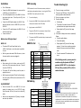
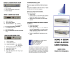
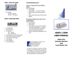
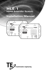
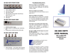
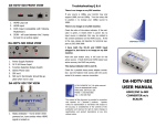
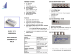
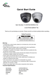
Package Contents HDMI-1-E FRONT VIEW 1 x HDMI-1-E or 1 x HDMI-1-R (Both of above when purchased in a set) User Manual (s) Power Supplies (5V 1A) (2 of above when purchased in a set) 1. HDMI Input from the Source HDMI-1-E REAR VIEW Features Uses the latest HDBase-T technology Extends 1080p signals up to 330 feet (100 meters) With a single CATx cable Supports HDMI 1.4 with 3D function Supports HDMI 1.2 and 1.3a HDCP Compliant Supports 3D pass-through Supports CEC pass-through Supports RS-232 (Bi-directional transfer) Supports al frequency band IR control 1. 2. 3. 4. Link Activity Status (Green) Local Power Status (Amber) RJ45 for CATx Output to Receiver 5V 1A Power HDMI-1-R FRONT VIEW Specifications HDMI-1-E HDMI-1-R USER MANUAL FEATURES/MODEL HDBT-1-E HDMI In 1 x HDMI A-Type Female HDMI Out RJ-45 HDMI CATx Extender / Receiver Max Resolution Cable Distance Power Adapter Dimension (mm) HDBT-1-R None 1 1 x HDMI A-Type Female 1 1080p 60Hz 1080p 60Hz 1. Cable Equalization Adjustment 2. HDMI Output to the Monitor 35m/115ft @ 1080p 35m/115ft @ 1080p 5V 1A DC 5V 1A DC 69 W x 39 x D 21 H 69 W x 39 x D 21 H 1. 2. 3. 4. Link Activity Status (Green) Local Power Status (Amber) RJ45 for CATx Output to Receiver 5V 1A Power Installation Turn off all devices Turn the EQ adjustment knob on the HDMI-1-R all the way counter clock wise. This will put the EQ in the “Auto Position” Connect the HDMI cable between the source and the <HDMI IN> port of the HDMI-1-E Connect the HDMI cable between the HDMI-1-R between the monitor and the <HDMI OUT> port of the HDMI-1-R Connect the CATx cable between the HDMI-1-E and HDMI-1-R’s RJ45 ports HDMI-1-E The amber LED (Local Power Status) on the HDMI-1-E will come on, once the power is applied to the unit Both the green and amber LEDs will come on, when the power and the source are plugged in HDMI-1-R When starting for the first time, make sure the EQ Trouble Shooting Q/A EDID mismatch is one of the most common problem in the display and extender industry. Learning the EDID on the HDMI-1-E can easily solve this issue 1. Turn on the display 2. Connect the HDMI-1-E to the display with a HDMI cable (do not connect the CATx cable) 3. Apply power to the HDMI-1-E 4. The green LED will lit for one second, then off, and the amber LED will remain flashing 5. This means the EDID from the display is now stored in the HDMI-1-E Connect the Power What do the LED Lights Mean? EDID Learning HDMI Pin Out Pin Signal # 1 TMDS Data 2+ Pin Signal # 11 TMDS Clock Shield 2 TMDS Data 2 Shield 12 TMDS Clock - 3 TMDS Data 2- 13 CEC 4 TMDS Data 1+ 14 knob is turn all the way counter clock wise. This puts the unit to “AUTO” EQ Reserved (N.C. on device) 5 TMDS Data 1 Shield 15 SCL The amber LED will be flashing once the power is applied to the unit 6 TMDS Data 1- 16 SDA 7 TMDS Data 0+ 17 DDC/CEC Ground 8 TMDS Data 0 Shield 18 +5 Power 9 TMDS Data 0- 19 Hot Plug Detect 10 TMDS Clock+ Both the green and amber LEDs will be lit and steady, when the power, HDMI monitor cable and the CATx are plugged in Cable Length The quality of the cable, low skew FTP cables performs better than regular network cables Slowly adjust the EQ knob until the image appears Q: The output of display have noise or occasionally flashes Check the cable distance Check for excessive RF interference in the room Check cable quality Slowly adjust the EQ knob until the image appears. It is best to use a pattern generator instead of the source to perform this adjustment If the flashing persists, you may want to consider using the Apantac HD Base T products (HDBT-SET-1) or the Apantac DVI over fiber products (DVI-xx-SC) to resolve this issue CATx Wiring EQ ADJUSTMENT When the amber LED on the HDMI-1-R is lit and Q: There is no image on my Monitor A: This may be an EDID issue. Follow the EDID learning procedure described earlier Q: There is no image on my Monitor A: Check the following steady, this means the unit is in AUTO EQ mode. Once the amber LED is off, the unit is in manual EQ mode. Identification Make sure you adjustment the EQ slowly, the adjustment are very sensitive Pair 2 Pair 1 Pair 3 Pair 4 Pin Assignment 5 4 1 2 3 6 7 8 Color Code White-Blue Blue White-Orange Orange White-Green Green White-Brown Brown © 2012 APANTAC LLC, All rights reserved 7556 SW BRIDGEPORT ROAD PORTLAND, OR 97224, USA PHONE +1 503 968 3000, FAX +1 503 389 7921 The content of this document are provided in connection with Apantac LLC (“Apantac”) products. Apantac makes no representation or warranties with respect to the accuracy or completeness of the contents of this publication and reserves the right to make changes to specifications and product descriptions at any time without notice