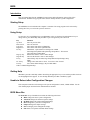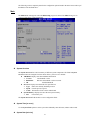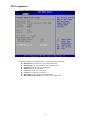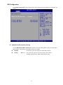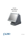
1
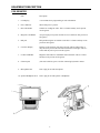
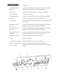
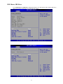
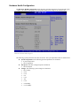
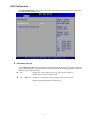
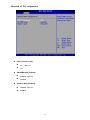
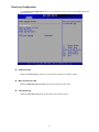
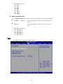
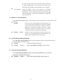
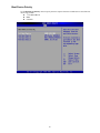
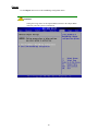
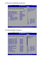
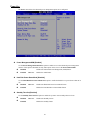
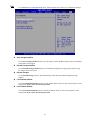
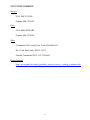
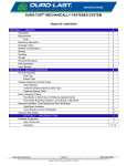
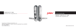
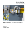
ViGo POS
MODEL M60XX-XX
USERS GUIDE
PN770500501
PAR warrants its products to be free of manufacturing defects. Please refer to the back of the sales contract for warranty
terms and conditions.
This document may contain technical or typographical errors. PAR reserves the right to change the document or the
product it describes at any time.
TABLE OF CONTENTS
INTRODUCTION………………………………………………………………………….4
GLOSSARY OF TERMS…………………………………………………………..4
EQUIPMENT DESCRIPTION…………………………………………………………….5
POS REGISTER……………………………………………………………………5
CONNECTOR WELL……………………………………………………………...7
SPECIFICATIONS………………………….……………………………………..8
BIOS………………………………………………………………………………………..9
i
INTRODUCTION
This manual will guide you through the initial setup; guide will inform you of what you can expect when you
first use ViGo POS system. It is presented in three parts as outlined in the table below.
Introduction
Purpose of manual.
Equipment Description
Specifications, a detailed description of each system
components.
Bios
Provides information on BIOS configurations.
GLOSSARY OF TERMS
♦
LCD – Liquid Crystal Display
♦
VGA – Video Graphics Array
♦
LAN – Local Area Network
♦
DDR – Double Data Rate
♦
POS – Point of Sale
♦
BIOS – Basic Input Output System
♦
UPS – Uninterruptible Power Supply
♦
PIN – Personal Identification Number
♦
KVS – Kitchen Video System
♦
HDD – Hard Disk Drive
♦
PCI – Peripheral Component Interconnect
♦
PnP – Plug and Play
♦
IDE – Integrated/Intelligent Drive Electronics
♦
ACPI – Advanced Configuration and Power Interface
4
EQUIPMENT DESCRIPTION
POS REGISTER
Item
Description
1.
LCD display
A screen that shows programming or order information.
2.
Power indicator
Shows that power is present.
3.
Bar Code Reader
Scanner for reading bar codes. This is a feature and may not be present
on all registers.
4.
Magnetic Card Reader
Accepts employee keycards. Provides access to functions. Not present on
all registers.
5.
PIN pad
PIN pad allowing the use of debit cards. This is a feature and may not be
present on all registers.
6.
Customer Display
Displays to the customer order total, tax total, and any changes due. It
may also show present advertisement information or messages. This is a
feature and may not be present on all registers.
7.
Credit Card Reader
Magnetic card reader for credit/debit card transactions. This is a feature
and may not be present on all registers.
8.
USB 2.0 ports
(Universal serial bus) ports. Used for connecting keyboard or mouse.
9.
Microphone Jack
Jack to plug in external microphone.
10. Speaker/Headphone Jack
Jack to plug in external speaker or headphone.
5
Item
11. Power switch
Description
Push in momentarily to turn “on”, push and hold to turn “off”. You can
reach it by sliding your hand under the right side of the register toward
the back. Leave the register on at all times, except when servicing the
unit. If a register is not plugged into an uninterruptible power supply
(UPS), you must turn it off during power failures as well.
11
6
CONNECTOR WELL
Item
Description
13. COMM serial port 1
(RS-232-C)
Connects to coin dispensers, remote customer displays, remote order
displays, EFT devices, printers, and other serial devices.
14. Printer port
Connects to a cable from a printer—A Centronics-compatible.
15. LAN receptacle
Connects to a LAN cable.
16. COMM serial port 4
(RS-232-C)
Connects to coin dispensers, remote customer displays, remote order
displays, EFT devices, printers, and other serial devices.
17. Status lights
Provide troubleshooting information to service personnel. (KVS, HDD,
Power, Status).
18. COMM serial port 7
(RS-232-C)
Connects to coin dispensers, remote customer displays, remote order
displays, EFT devices, printers, and other serial devices.
19. COMM serial port 2
(RS-232-C)
Connects to coin dispensers, remote customer displays, remote order
displays, EFT devices, printers, and other serial devices.
20. COMM serial port 3
(RS-232-C)
Connects to coin dispensers, remote customer displays, remote order
displays, EFT devices, printers, and other serial devices.
21. Keyboard receptacle
Allows connection of a PC keyboard (mini DIN).
22. MSR
Magnetic strip reader.
23. Cash drawer receptacle
Connect to the cables from up to two cash drawers.
24. Remote video receptacle
Connects to the cable from the remote video controller.
(Universal serial bus) Connect to other devices like coin dispensers or
printers.
25. USB connectors
7
SPECIFICATIONS
ViGo POS Features:
♦
Processors
o F6100R – 2.0GHz Celeron Processor w/fan
o F6101R – 2.0GHz Pentium 4 Processor w/fan
o F6102R– 2.5GHz Celeron Processor w/fan
o F6103R – 2.4GHz Pentium 4 Processor w/fan
o F6104R – 2.8GHz Pentium 4 Processor w/fan
♦
Memory
o F6201R – 256 MB DDR SDRAM
o F6202R - 512MB DDR SDRAM
o F6203R - 1GB DDR SDRAM
♦
Magnetic Strip Readers
o F6300R – Operator 2 Track Mag Strip Reader Swipe
o F6303R – 3-Track Mag Stripe reader (crew side)
o F6320R – Blank Cover Plate (when no MSR ordered)
♦
Hard Drive/CD ROM/DVD
o F6400R – 3.5” 10GB Hard Disk Drive
o F6430R – DVD-RW Drive Laptop Style Thin
o F6435R – CD-ROM Drive Ultra Slim
PCI Option Cards
o F6500R – 512 KB BB SRAM
o F6550R – Mini-PCI 802.11 G Wireless LAN
♦
ViGo POS Options:
♦
F6700R - Stereo Audio/Dual USB
♦
F6750R – Powered USB
8
BIOS
Introduction
This user manual describes the AMI BIOS setup program and configuration options of the ViGo
motherboard. The BIOS setup program allows users to modify the basic system configuration.
Starting Setup
The AMI BIOS is activated when the computer is turned on. The setup program can be activated by
pressing the F2 key as soon as the system is turned on.
Using Setup
Use the arrow keys to highlight items, press ENTER to select, use the PageUp and PageDown keys to
change entries, press F1 for help and press ESC to quit. Navigation keys are shown in.
Key
Function
Up arrow
Down arrow
Left arrow
Right arrow
Esc key
Move to previous item
Move to next item
Move to the item on the left hand side
Move to the item on the right hand side
Main Menu – Quit and not save changes into CMOS
Status Page Setup Menu and Option Page Setup Menu -- Exit current
page and return to Main Menu
Page Up key
Increase the numeric value or make changes
Page Dn key
Decrease the numeric value or make changes
F1 key
General help, only for Status Page Setup Menu and Option Page Setup
Menu
F2 /F3 key
Change color from total 16 colors. F2 to select color forward.
F10 key
Save all the CMOS changes, only for Main Menu
Table 1-1: BIOS Navigation Keys
Getting Help
When F1 is pressed a small help window describing the appropriate keys to use and the possible selections
for the highlighted item appears. To exit the Help Window press ESC or the F1 key again.
Unable to Reboot after Configuration Changes
If the computer cannot boot after changes to the system configuration is made, CMOS defaults. Use the
clear CMOS jumper described in the motherboard user manual.
BIOS Menu Bar
The menu bar on top of the BIOS screen has the following main items:
Main Changes the basic system configuration.
Advanced Changes the advanced system settings.
PCIPnP Changes the advanced PCI/PnP Settings
Boot Changes the system boot configuration.
Chipset Changes the chipset settings.
Power Changes power management settings.
Exit Selects exit options and loads default settings
9
The following sections completely describe the configuration options found in the menu items at the top of
the BIOS screen and listed above.
Main
The Main BIOS menu appears when the BIOS Setup program is entered. The Main menu gives an
overview of the basic system information.
BIOS Menu 1: Main
System Overview
The System Overview lists a brief summary of different system components. The fields in System
Overview cannot be changed. The items shown in the system overview include:
AMI BIOS: Displays auto-detected BIOS information
o Version:
Current BIOS version
o Build Date:
Date the current BIOS version was made
o ID:
Installed BIOS ID
Processor: Displays auto-detected CPU specifications
o Type: Names the currently installed processor
o Speed: Lists the processor speed
o Count: The number of CPUs on the motherboard
System Memory: Displays the auto-detected system memory.
o Size: Lists memory size
The System Overview field also has two user configurable fields:
System Time [xx:xx:xx]
Use the System Time option to set the system time. Manually enter the hours, minutes and seconds.
System Date [xx/xx/xx]
10
Use the System Date option to set the system date. Manually enter the day, month and year.
Advanced
Use the Advanced menu to configure the CPU and peripheral devices through the following sub-menus:
WARNING:
Setting the wrong values in the sections below may cause the system to
malfunction. Make sure that the settings made are compatible with the
hardware.
CPU Configuration
IDE Configuration
SuperIO Configuration
Hardware Health Configuration
ACPI Configuration
Event Log Configuration
USB Configuration
BIOS Menu 2: Advanced
11
CPU Configuration
Use the CPU Configuration menu to view detailed CPU specifications and configure the CPU.
BIOS Menu 3: CPU Configuration
The CPU Configuration menu (BIOS Menu 3) lists the following CPU details:
Manufacturer: Lists the name of the CPU manufacturer
Brand String: Lists the brand name of the CPU being used
Frequency: Lists the CPU processing speed
FSB Speed: Lists the FSB speed
Cache L1: Lists the CPU L1 cache size
Cache L2: Lists the CPU L2 cache size
Ratio Status: Values in option are predetermined
Max CPUID Value Limit: Values in option are predetermined
12
IDE Configuration
Use the IDE Configuration menu to change and/or set the configuration of the IDE devices installed in the
system.
BIOS Menu 4: IDE Configuration
OnBoard PCI IDE Controller [Primary]
Use the OnBoard PCI IDE Controller BIOS option to specify the IDE channels used by the onboard PCI
IDE controller. The following configuration options are available.
Prevents the system from using the onboard IDE controller
Disabled
Primary
DEFAULT
Only allows the system to detect the Primary IDE channel,
including both the Primary Master and the Primary Slave
13
IDE Master, IDE Slave
Use the IDE Master and IDE Slave configuration menu to view both primary and secondary IDE device
details and configure the IDE devices connected to the system.
14
Super IO Configuration
Use the Super IO Configuration menu to set or change the configurations for the FDD controllers,
parallel ports and serial ports.
BIOS Menu 5: Super IO Configuration
Serial Port Address
Use the Serial Port Address option to select the Serial Port base address.
No base address is assigned to Serial Port
Disabled
Port IRQ Options:
♦
♦
♦
♦
♦
♦
IRQ 3
IRQ 4
IRQ 5
IRQ 11
IRQ 12
IRQ 15
15
Hardware Health Configuration
The Hardware Health Configuration menu shows the operating temperature, fan speeds and system
voltages. The values in image may not correspond to POS system, image is for reference only.
BIOS Menu 6: Hardware Health Configuration
The following system parameters and values are shown. The system parameters that are monitored are:
System Temperatures: The following system temperatures are monitored
o System Temperature
o CPU Temperature
Fan Speeds: The CPU cooling fan speed is monitored.
o CPU Fan Speed
Voltages: The following system voltages are monitored
o CPU Voltage
o +2.5V
o +3.3V
o +5V
o +12V
o -12V
o +1.5V
o +5V Standby
o +3.3V Standby
16
ACPI Configuration
The ACPI Configuration menu configures the Advanced Configuration and Power Interface (ACPI) and
Power Management (APM) options.
BIOS Menu 7: ACPI Configuration
ACPI Aware O/S [Yes]
Use the ACPI Aware O/S option to enable the system to configure ACPI power saving options. ACPI can
only be implemented if the system OS complies with the ACPI standard. Windows 98, Windows 2000, and
Windows XP all comply with ACPI.
Disables the ACPI support for the OS. This selection should be
No
disabled if the OS does not support ACPI
Yes
DEFAULT
Enables the ACPI support for the operating system. This selection
should be enabled if the OS does support ACPI
17
Advanced ACPI Configuration
BIOS Menu 8: ACPI Configuration
ACPI 2.0 Features [No]
No
DEFAULT
Yes
AMI OEMB table [Enabled]
Enabled
DEFAULT
Disabled
Headless Mode [Disabled]
Disabled
DEFAULT
Enabled
18
Event Log Configuration
Use the Event Log Configuration menu to view or delete the system event log storing POSt and run-time
errors and events.
BIOS Menu 9: Event Log Configuration
View Event Log
Enable the View Event Log option to view all unread event entries in a display window.
Mark all events as read
Enable the Mark all events as read option to mark all unread events as read.
Clear Event Log
Enable the Clear Event Log option to discard all events in the Event Log.
19
USB Configuration
Use the USB Configuration menu to read USB configuration information and configure the USB settings.
BIOS Menu 10: USB Configuration
USB Configuration
The USB Configuration field shows the system USB configuration. The items listed are:
Module Version: x.xxxxx.xxxxx
USB Devices Enabled
The USB Devices Enabled field lists the USB devices that are enabled on the system
Legacy USB Support [Enabled]
The Legacy USB Support BIOS option refers to USB mouse and USB keyboard support. Normally if this
option is not enabled, any attached USB mouse or USB keyboard does not become available until a USB
compatible operating system is fully booted with all USB drivers loaded. When this option is enabled, any
attached USB mouse or USB keyboard can control the system even when there is no USB driver loaded on
the system.
Legacy USB support disabled
Disabled
Enabled
DEFAULT
Legacy USB support enabled
USB2.0 Controller Mode [HiSpeed]
Use the USB2.0 Controller Mode option to set the speed of the USB2.0 controller.
The controller is capable of operating at 12Mb/s
FullSpeed
HiSpeed
DEFAULT
The controller is capable of operating at 480Mb/s
20
PCI/PnP
Use the PCI/PnP menu to configure advanced PCI and PnP settings.
WARNING!
Setting wrong values for the BIOS selections in the PCIPnP BIOS menu may
cause the system to malfunction.
BIOS Menu 11: PCI/PnP Configuration
Plug & Play O/S [No]
Use the Plug & Play O/S BIOS option to specify whether system plug and play devices are configured by
the operating system or the BIOS.
No
DEFAULT If the operating system does not meet the Plug and Play
specifications, this option allows the BIOS to configure all the
devices in the system.
Yes
This setting allows the operating system to change the interrupt,
I/O, and DMA settings. Set this option if the system is running
Plug and Play aware operating systems.
IRQ# [Available]
Use the IRQ# address to specify what IRQs can be assigned to a particular peripheral device.
The specified IRQ is available to be used by PCI/PnP
Available
DEFAULT
devices
Reserved
The specified IRQ is reserved for use by Legacy ISA
devices
21
Available IRQ addresses are:
IRQ3
IRQ4
IRQ5
IRQ7
IRQ9
IRQ 10
IRQ 11
IRQ 14
DMA Channel# [Available]
Use the DMA Channel# option to assign a specific DMA channel to a particular PCI/PnP device.
The specified DMA is available to be used by PCI/PnP
Available
DEFAULT
devices
Reserved
The specified DMA is reserved for use by Legacy ISA
devices
Available DMA Channels are:
DM Channel 0
DM Channel 3
DM Channel 5
DM Channel 6
DM Channel 7
Boot
Use the Boot menu to configure system boot options.
BIOS Menu 12: Boot
22
Boot Settings Configuration
Use the Boot Settings Configuration menu to configure advanced system boot options.
BIOS Menu 13: Boot Settings Configuration
Quick Boot [Enabled]
Use the Quick Boot BIOS option to make the computer speed up the boot process.
No POST procedures are skipped
Disabled
Enabled
DEFAULT
Some POST procedures are skipped to decrease the
system boot time
AddOn ROM Display Mode [Force BIOS]
Use the AddOn ROM Display Mode option to allow add-on ROM (read-only memory) messages to be
displayed.
Force BIOS
DEFAULT The system forces third party BIOS to display during
system boot.
The system displays normal information during system
boot.
Keep Current
Bootup Num-Lock [On]
Use the Bootup Num-Lock BIOS option to specify if the number lock setting must be modified during
boot up.
Off
Does not enable the keyboard Number Lock automatically. To use
23
the 10-keys on the keyboard, press the Number Lock key located on
the upper left-hand corner of the 10-key pad. The Number Lock
LED on the keyboard lights up when the Number Lock is engaged.
On
DEFAULT
Allows the Number Lock on the keyboard to be enabled
automatically when the computer system boots up. This allows the
immediate use of the 10-key numeric keypad located on the right
side of the keyboard. To confirm this, the Number Lock LED light
on the keyboard is lit.
Wait For ‘F1’ If Error [Enabled]
Use the Wait for ‘F1’ if Error option to specify how the system responds when the system detects an error
on boot up.
If there is an error when booting up, the system does not wait
Disabled
for user intervention but continues to boot up in the operating
system. Only use this setting if there is a known reason for a
BIOS error to appear. An example would be a system
administrator must remote boot the system. The computer
system does not have a keyboard currently attached.
Enabled
DEFAULT
If there is an error during boot up, the system waits for a user
to press “F1” and enter the BIOS to rectify the problem. The
BIOS can then be adjusted to the correct settings.
Hit ‘DEL’ Message Display [Enabled]
Use the Hit “DEL” Message Display option to specify whether the instruction to hit the delete button to
enter BIOS during POST appears or not.
No message displayed during POST
Disabled
Enabled
DEFAULT
Displays “Press DEL to run Setup” message in POST
Interrupt 19 Capture [Disabled]
Use the Interrupt 19 Capture option to allow optional ROMs such as network
controllers to trap BIOS interrupt 19.
Disabled
DEFAULT
Does not allow optional ROM to trap interrupt 19
24
Boot Device Priority
Use the Boot Device Priority menu to specify the boot sequence from the available devices. Possible boot
devices may include:
1st FLOPPY DRIVE
HDD
CD/DVD
25
Chipset
Use the Chipset menu to access the NorthBridge configuration menu.
WARNING!
Setting the wrong values for the Chipset BIOS selections in the Chipset BIOS
menu may cause the system to malfunction.
BIOS Menu 14: Chipset
26
Intel Brookdale-G NorthBridge Configuration
Use the NorthBridge Configuration menu to configure the northbridge chipset.
BIOS Menu 15:NorthBridge Chipset Configuration
Intel ICH4 SouthBridge Configuration
Use the SouthBridge Configuration menu to configure the southbridge chipset.
27
Power Key
The Power menu allows the advanced power management options to be configured.
BIOS Menu 16:Power
Power Management/APM [Enabled]
Use the Power Management/APM BIOS option to enable access to the advanced power management
features. If this option is disabled, the only other option on the screen is the Power Button Mode.
Disables the Advanced Power Management (APM) feature
Disabled
Enabled
DEFAULT
Enables the APM feature
Hard Disk Power Down Mode [Disabled]
Use the Hard Disk Power Down Mode BIOS option to enable the hard drive to power down when not in
use.
Disabled
DEFAULT Disables the Hard Disk Power Down Mode feature
Enabled
Enables the Hard Disk Power Down Mode feature
Standby Time Out [Disabled]
Use the Standby Time Out BIOS option to enable the system to enter standby when not in use.
Disabled
DEFAULT Disables the Standby feature
Enabled
Enables the Standby feature
28
System Thermal [Disabled]
Disabled
DEFAULT
Enabled
Disables the System Thermal feature
Enables the System Thermal feature
Power Button Mode [On/Off]
Use the Power Button Mode BIOS to specify how the power button functions.
On/Off
DEFAULT When the power button is pressed the system is either turned
on or off
Suspend
When the power button is pressed the system goes into
suspend mode
Restore on AC Power Loss [Power Off]
The Restore on AC Power Loss BIOS option specifies what state the system returns to if there is a sudden
loss of power to the system.
Power Off
DEFAULT The system remains turned off
Power On
The system turns on
Last State
The system returns to its previous state. If it was on, it turns
itself on. If it was off, it remains off.
Resume on Ring [Disabled]
Use the Resume on Ring BIOS to specify if the system resumes on ring from the modem.
Disabled
DEFAULT Disables Resume on Ring feature
Enabled
Enables Resume on Ring feature
29
Exit
Use the Exit menu to load default BIOS values, optimal failsafe values and to save configuration changes.
BIOS Menu 17:Exit
Save Changes and Exit
Use the Save Changes and Exit option to save the changes made to the BIOS options and to exit the BIOS
configuration setup program.
Discard Changes and Exit
Use the Discard Changes and Exit option to exit the BIOS configuration setup program without saving
the changes made to the system.
Discard Changes
Use the Discard Changes option to discard the changes and remain in the BIOS configuration setup
program.
Load Optimal Defaults
Use the Load Optimal Defaults option to load the optimal default values for each of the parameters on the
Setup menus. F9 key can be used for this operation.
Load Failsafe Defaults
Use the Load Failsafe Defaults option to load failsafe default values for each of the parameters on the
Setup menus. F8 key can be used for this operation.
30
PAR PHONE NUMBERS
Service
USA: 800.382.6200
Canada: 800.387.4963
Parts
USA: 800.PAR.PART
Canada: 800.387.4963
Sales
Continental USA except New York: 800.448.6505
New York State Only: 800.533.6311
Outside Continental USA: 315-738-0600
Driver Support
http://www.partech.com/pti_products_services/service_existing_customer.cfm
31