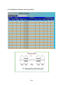
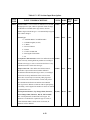
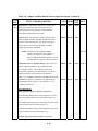
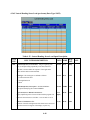
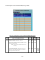
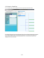
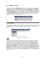
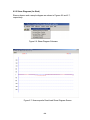
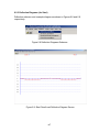
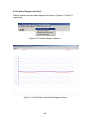
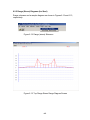
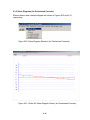
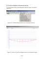
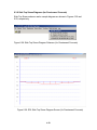
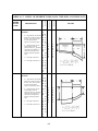
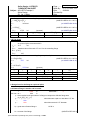
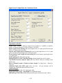
1
DESIGN, ANALYSIS AND RATING OF STRAIGHT GIRDER BRIDGE SYSTEMS The BEST Center Bridge Engineering Software & Technology Center Department of Civil Engineering University of Maryland May 12, 2014 WIN-DASH1 User Manual TABLE OF CONTENTS 1.0 INTRODUCTION ........................................................................................................... 1-1 1.1 Abstract ................................................................................................................ 1-1 1.2 History of MERLIN-DASH................................................................................. 1-2 1.3 Support for MERLIN-DASH............................................................................... 1-2 2.0 OVERVIEW .................................................................................................................... 2-1 2.1 Program Capabilities............................................................................................ 2-1 System Features Specifications Unit Systems Structural Model Live Load Dead Load Analysis Code Check Graphics Rating Detailed Design Optimum Design 2.2 Methodology ........................................................................................................ 2-5 Analysis Design Dead Loadings Live Load Maxima AASHTO Loadings Special Loadings Definition of Trucks Moment/Shear Interaction Rating Staging 3.0 USING MERLIN-DASH................................................................................................. 3-1 3.1 Before You Begin ................................................................................................ 3-1 3.2 Accessing the Main Menu ................................................................................... 3-1 3.3 The WIN-DASH Main Menu Visual Input Utility Run Utility Graphic Utility Post Processor Print Utility Exit 1 MERLIN-DASH for WINDOWS i Help Utility 4.0 INPUT UTILITY ............................................................................................................. 4-1 4.1 Main Menu .......................................................................................................... 4-1 File Menu Toolbar Tips: DASH input data file or DASH XML file? 4.2 Data Input Pages...…………...…...………...……………………...……........... 4-3 Navigate to a Data Input Page 4.2.1 System...................................................................................................... 4-5 4.2.1A Project Data.................................................................................. 4-5 4.2.1B General Program Options............................................................. 4-6 4.2.2 Structure Framing .................................................................................... 4-8 4.2.2A Structural Details.......................................................................... 4-9 4.2.2B Span Length (For non-PC Bridge) ............................................. 4-11 4.2.2C Span Length (For PC Bridge only) ............................................ 4-12 4.2.2D Hinge Locations ......................................................................... 4-13 4.2.2E Beam Spacing............................................................................. 4-14 4.2.2F Boundary Conditions .................................................................. 4-15 4.2.3 Beam Definition..................................................................................... 4-16 4.2.3.1 Steel…………………................................................................ 4-16 4.2.3.1A Wide Flange ,Plate Girder ........................................... 4-16 4.2.3.1B Definition of Members ................................................ 4-18 4.2.3.2 Reinforced Concrete………………….. .................................... 4-22 4.2.3.2A RC Section... ............................................................... 4-22 4.2.3.2B RC Reinforcement Details .......................................... 4-25 4.2.3.2C Definition of Members ................................................ 4-26 4.2.3.3 Prestressed Concrete………………….. .................................... 4-28 4.2.3.3A PC Section................................................................... 4-28 4.2.3.3B PC Reinforcement Details........................................... 4-30 4.2.3.3C Definition of Tendons ................................................. 4-31 4.2.4 Factor Definition.................................................................................... 4-33 4.2.4A Impact and Distribution Factors (WSD/LFD) ........................... 4-33 4.2.4B Impact and Distribution Factors (LRFD) ................................... 4-34 4.2.4C Gamma and Beta (WSD or LFD)............................................... 4-38 4.2.4D Load and Resistance Factor (LRFD) ......................................... 4-39 4.2.5 Live Load ............................................................................................... 4-41 4.2.5A AASHTO Live Load.................................................................. 4-41 4.2.5B State Vehicle Loading ................................................................ 4-43 4.2.5C General Vehicles ........................................................................ 4-44 4.2.5D Special Vehicle Loading (Load Type C) ................................... 4-45 4.2.6 Dead Load.............................................................................................. 4-46 4.2.6A Slab Loads.................................................................................. 4-46 4.2.6B Arbitrary Uniform and Concentrated Loads .............................. 4-47 4.2.6C Lateral Bending Stress Load ...................................................... 4-49 4.2.6D Auto Generation of Dead and Superimposed Dead Loads ........ 4-50 4.2.7 Design (Used for Flow Control = 4 or 6 only) ...................................... 4-52 4.2.7A Splice Design Data..................................................................... 4-52 ii 4.2.7B Design Method and Stiffener Option ......................................... 4-53 4.2.7C Designated Plate Size ................................................................. 4-54 4.2.7D Design Plate Size Range ............................................................ 4-55 4.2.7E Material and Fabrication Cost .................................................... 4-56 4.2.7F Field Splice Location and Material ID ....................................... 4-57 4.2.8 Property ................................................................................................. 4-58 4.2.8.1 Steel and Reinforced Concrete................................................... 4-58 4.2.8.1A Reinforced Concrete Strength Data ............................ 4-58 4.2.8.2 Prestressed Concrete .................................................................. 4-60 4.2.8.2A Prestressing Steel Properties ....................................... 4-61 4.2.8.2B Post-tension Steel Material Properties ........................ 4-62 4.2.8.2C Prestress Concrete Slab ............................................... 4-63 4.2.8.2D Precast Beam............................................................... 4-64 4.2.9 Detail.. .................................................................................................... 4-66 4.2.9A Girder Field Stress and Lateral Bracing .................................... 4-66 4.2.9B Longitudinal Stiffener ............................................................... 4-68 4.2.9C Transverse Stiffener .................................................................. 4-70 4.3 Use Excel Work Sheet to Enter Data ................................................................ 4-71 Graphic Pages ……………………………………………………………...….4-75 4.3A Navigate to a Graphic Page.................................................................... 4-76 4.3B Plan View............................................................................................... 4-77 4.3C Bridge .................................................................................................... 4-78 4.3D Sections .................................................................................................. 4-83 4.3D.1 W/PG Sections ........................................................................... 4-83 4.3D.2 PC Sections ................................................................................ 4-84 4.3D.3 RC Sections................................................................................ 4-85 4.3E Girder .................................................................................................... 4-86 4.3F Girder Profile and Loads........................................................................ 4-87 4.3G PC Tendon Configuration ...................................................................... 4-88 4.3H Trucks .................................................................................................... 4-89 4.3H.1 General Vehicle.......................................................................... 4-89 4.3H.2 Dump and Allowable Truck....................................................... 4-90 4.3H.3 Special Vehicle .......................................................................... 4-91 4.3I Zoom and Pan of a 2D Graphic View.................................................... 4-92 4.3J Interactive in 3D Graphic View............................................................. 4-94 5.0 RUN UTILITY ................................................................................................................ 5-1 5.1 Single Run............................................................................................................. 5-1 5.2 Multiple Run ......................................................................................................... 5-2 5.3 Single/Multiple Run Exit ...................................................................................... 5-3 6.0 GRAPHICS UTILITY ..................................................................................................... 6-1 6.1 File Submenu ....................................................................................................... 6-1 Open Print Screen Close iii 6.2 6.3 7.0 Exit Graphic Plots (for Steel) ...................................................................................... 6-3 6.2.1 Moment Diagrams ................................................................................... 6-5 6.2.2 Shear Diagrams........................................................................................ 6-6 6.2.3 Deflection Diagrams ................................................................................ 6-7 6.2.4 Camber Diagrams .................................................................................... 6-8 6.2.5 Range (Stress) Diagrams.......................................................................... 6-9 6.2.6 Stress Diagrams ..................................................................................... 6-10 6.2.6.1 Top Flange Stress Diagrams ...................................................... 6-10 6.2.6.2 Bottom Flange Stress Diagrams ................................................ 6-11 Graphic Plots (for Prestressed Concrete)........................................................... 6-12 6.3.1 Moment Diagrams ................................................................................. 6-15 6.3.2 Shear Diagrams...................................................................................... 6-16 6.3.3 Displacement Diagrams ......................................................................... 6-17 6.3.4 Bottom Stress Diagrams ........................................................................ 6-18 6.3.5 Top Stress Diagrams .............................................................................. 6-19 6.3.6 Slab Top Stress Diagrams...................................................................... 6-20 PRINT UTILITY ............................................................................................................. 7-1 7.1 Open File.............................................................................................................. 7-2 7.2 View/Print File..................................................................................................... 7-2 7.3 View Tables ......................................................................................................... 7-4 7.4 Print Tables .......................................................................................................... 7-5 7.5 Exit....................................................................................................................... 7-5 7.6 Output Definitions and Options ........................................................................... 7-6 7.6.1 Index of Output Tables ............................................................................ 7-6 7.6.2 Output Options......................................................................................... 7-7 7.6.3 Definition of Output............................................................................... 7-12 REFERENCES iv TABLES 2.1 2.2 2.3 2.4 4.1 4.2 4.3 4.4 4.4A 4.5 4.6 4.7 4.8 4.9 4.10 4.11 4.12 4.13 4.14 4.15 4.16 4.17 4.18 4.19 4.20 4.21 4.22 4.23 4.24 4.25 4.26 4.27 4.28 4.29 4.30 4.31 4.32 4.33 4.34 4.35 4.36 4.37 4.38 4.39 4.40 6.1 Summary of Features and Options................................................................................... 2-3 Assumptions..................................................................................................................... 2-6 Program Limits ................................................................................................................ 2-6 Loading Assumptions ...................................................................................................... 2-7 Project Data Input Description......................................................................................... 4-6 General Program Options Input Description ................................................................... 4-7 Structural Details Input Description ................................................................................ 4-9 Span Lengths Input Description..................................................................................... 4-11 Span Lengths Input Description (For PC Bridge only).................................................. 4-12 Hinge Locations Input Description................................................................................ 4-13 Beam Spacing Input Description ................................................................................... 4-14 Boundary Condition Input Description.......................................................................... 4-15 Flanged Sections Input Description ............................................................................... 4-17 Definition of Members Input Description...................................................................... 4-19 Reinfored Concrete Section Input Description .............................................................. 4-23 RC Reinforcement Detail Input Description.................................................................. 4-25 Definition of Members Input Description (For RC) ...................................................... 4-27 PC Sections Input Description ....................................................................................... 4-29 PC Reinforcement Input Description............................................................................. 4-30 Member and Tendon Geometry Data Input Description ............................................... 4-32 Impact and Distribution Factors Input Description ....................................................... 4-34 Load Factors; Gamma and Beta Input Description........................................................ 4-38 Load Factors; LRFD Option .......................................................................................... 4-40 AASHTO Live Load Input Description......................................................................... 4-42 State Vehicle Loading Input Description....................................................................... 4-43 General Vehicles Input Description............................................................................... 4-44 Special Vehicle ID and Input Description ..................................................................... 4-45 Slab Loads Input Description......................................................................................... 4-46 Arbitrary Uniform and Concentrated Loads Input Description..................................... 4-48 Lateral Bending Stress Load Input Description............................................................. 4-49 Auto Generation of Dead and Superimposed Dead Loads ............................................ 4-51 Splice Design Data Input Description............................................................................ 4-52 Design Method and Stiffener Option Input Description................................................ 4-53 Designated Plate Size Input Description........................................................................ 4-54 Design Plate Size Range Input Description ................................................................... 4-55 Material and Fabrication Cost Input Description........................................................... 4-56 Field Splice Location and Material ID Input Description ............................................. 4-57 Reinforced Concrete Strength Data Input Description .................................................. 4-59 Prestressing Steel Properties Data Input Description .................................................... 4-61 Post-tension Steel Material Properties ........................................................................... 4-62 Slab Data Input Description........................................................................................... 4-63 Precast Beam Data Input Description ............................................................................ 4-65 Yield Stress and Lateral Bracing Data Input Description.............................................. 4-67 Longitudinal Stiffener Data Input Description .............................................................. 4-69 Transverse Stiffener Data Input Description ................................................................. 4-70 Graphic Plot Options (Steel)............................................................................................ 6-3 v 6.2 7.1 7.2 7.3 Graphic Plot Options (Prestressed Concrete) ................................................................ 6-12 Definition of Output Indices - TABLE I.J.K.L................................................................ 7-6 Definition of Output Tables for Composite Construction ............................................... 7-8 Error Messages............................................................................................................... 7-12 vi FIGURES 2.1 3.1 3.2 5.1 5.2 6.1 6.2 6.3 6.4 6.5 6.6 6.7 6.8 6.9 6.10 6.11 6.12 6.13 6.14 6.15 6.16 6.17 6.18 6.19 6.20 6.21 6.22 6.23 6.24 6.25 6.26 6.27 6.28 6.29 7.1 7.2 7.3 7.4 7.5 7.6 The Flow Chart of MERLIN-DASH ............................................................................... 2-2 WIN-DASH Title Screen................................................................................................. 3-2 WIN-DASH Main Menu Screen...................................................................................... 3-3 RUN Utility Screen.......................................................................................................... 5-1 Input Data File Window................................................................................................... 5-2 Graphics Utility Screen.................................................................................................... 6-1 File Submenu ................................................................................................................... 6-1 Open Graphic File Window ............................................................................................. 6-2 Moment Diagrams Submenu ........................................................................................... 6-5 Total Maximum Moment Diagram Screen ...................................................................... 6-5 Shear Diagram Submenu ................................................................................................. 6-6 Total Maximum Shear Diagram Screen .......................................................................... 6-6 Deflection Diagrams Submenu ........................................................................................ 6-7 Total Dead Load Deflection Diagram Screen.................................................................. 6-7 Camber Diagram Submenu.............................................................................................. 6-8 Total Dead Load Camber................................................................................................. 6-8 Range (Stress) Submenu .................................................................................................. 6-9 Top Flange Stress Range Diagram Screen....................................................................... 6-9 Top Flange Stress Submenu .......................................................................................... 6-10 Top Flange Maximum Total Positive and Allowable Stress Screen ............................. 6-10 Bottom Flange Stress Submenu ..................................................................................... 6-11 Bottom Flange Maximum Total Positive and Allowable Stress Screen........................ 6-11 Moment Diagram Submenu (Prestressed Concrete)...................................................... 6-15 Girder Wt. Moment Diagram Screen............................................................................. 6-15 Shear Diagram Submenu (Prestressed Concrete) .......................................................... 6-16 Girder Wt. Shear Diagram Screen ................................................................................. 6-16 Displacement Diagram Submenu (Prestressed Concrete) ............................................. 6-17 Girder Wt. Displacement Diagram Screen .................................................................... 6-17 Bottom Stress Diagram Submenu (Prestressed Concrete)............................................. 6-18 Girder Wt. Bottom Stress Diagram Screen.................................................................... 6-18 Top Stress Diagram Submenu (Prestressed Concrete) .................................................. 6-19 Girder Wt. Top Stress Diagram Screen ......................................................................... 6-19 Slab Top Stress Diagram Submenu (Prestressed Concrete) .......................................... 6-20 SDL Slab Top Stress Diagram Screen ........................................................................... 6-20 Print Utility Screen .......................................................................................................... 7-1 A Typical Result File Screen ........................................................................................... 7-2 Print File Window............................................................................................................ 7-3 Search String Window ..................................................................................................... 7-3 A Typical View Table Screen.......................................................................................... 7-4 A Typical Print Table Screen........................................................................................... 7-5 vii APPENDIX A Table A.1.2 Structural Data ........................................................................................................ A-2 Table A.1.3 Definition of Member Types .................................................................................. A-3 Table A.1.4 Allowable Live Load Types.................................................................................... A-4 Table A.1.5 Formulation of the Impact Factor ........................................................................... A-5 Table A.1.6 Definition of Distribution Factor Options............................................................... A-6 A1. EXAMPLES FOR ROLLED BEAM DESIGN AND STAGING A2. USER-SPECIFIED TRUCK FILE INPUT SHEET A3. MORE INSIGHT ABOUT MERLIN-DASH A4. WIN-DASH SPLICE DESIGN IN LRFD A5. INPUT PROCESSOR OPTION – SCREEN ORGANIZER APPENDIX B B1. LFD THEORY FOR PRESTRESSED CONCRE B2. LRFD THEORY FOR PRESTRESSED CONCRE B3. THEORY FOR STEEL BRIDGES APPENDIX C PIER CONTINUITY PC GIRDER LRFD DESIGN viii 1.0 INTRODUCTION 1.1 Abstract MERLIN-DASH (Design, Analysis and Rating of StraigHt Girder Bridge Systems) was developed for use by bridge design engineers who function in a software production environment. In order to provide a program which would be applicable nationally, the BEST Center developed MERLIN-DASH to offer the widest range of features and options possible. MERLIN-DASH incorporates a standardized sequence of steps starting with analysis and proceeding, at the user's option, to perform a code check, design and/or rating which allows for the following: 1. Analysis Only : For the analysis of dead and/or live load effects; 2. Analysis/Code Check: For analysis and then code checking; 3. Analysis/Rating : For rating or posting of existing structures; 4. Design : For design with weight or cost optimization; 5. Design/Code Check : Void; 6. Design/Code Check/Recycle : First design, then recycle to re-analyze the designed section, then perform a code check; 7. DL Stage Analysis : Dead Load pouring sequence stage analysis; 8. DL + LL Stage Analysis : Dead Load pouring sequence stage and Live Load analysis. The generality of the program also extends into the structural model incorporated within MERLIN-DASH. The structural analysis is performed using a series of modular subroutines which are based on the stiffness method. Utilizing this methodology allows the use of various specialized members such as straight and parabolic haunches, hinges, and flanged transitions. The loading capabilities of MERLIN-DASH include joint, concentrated and segmented uniform member loads. An extensive mesh generation capability allows for the incorporation of fully automated AASHTO Dead Load (DL) and Live Load (LL) sequences. A highly general and wide range of live load capabilities are also incorporated into MERLIN-DASH. 1. 2. 3. 4. 5. Standard AASHTO truck and lane loadings Non-standard AASHTO loadings (e.g., HS 25, HS 26, . . ., etc.) The interstate (or tandem) vehicle Various standard state truck configurations Generalized (user-specified) two- and three-axle trucks 1-1 6. A generalized, up to 20-axle, user-defined truck where direction of travel may be specified 7. Generalized predefined truck files. A more detailed description of the capabilities of MERLIN-DASH is given in Chapter 2. 1.2 History of MERLIN-DASH For nearly twenty years the Maryland State Highway Administration (MD SHA) Bureau of Bridge Development has sponsored research at the Department of Civil Engineering, University of Maryland College Park, to develop bridge design software. One of the first systems to be undertaken was the MERLIN-DASH program. Since the completion of the basic system in 1978, MERLIN-DASH has become widely used and has undergone numerous revisions and upgrades. The mainframe version was in use within various state and municipal design agencies. MERLIN-DASH was selected by the National Highway Research Program Committee 12-18 as the most general program for universal application on a national basis. It is also used by Federal Highway Administration (FHWA) demonstration project DP-81 “ Load Factor Design by Computers “ as a result of which delivered to over thirty states. 1.3 Support for MERLIN-DASH Both first and second level support are available to users on the operation, assumptions, and problems related to the MERLIN-DASH program. First level support, which is the first contact for all user initiated queries, is generally provided by the authorized vendor from whom the program was purchased. The BEST Center staff will provide second level, in-depth, technical support as a backup to the vendor for unresolved issues relating to first level support. In addition, the BEST Center will make: Bug Fixes: The BEST Center will make every effort to identify and rectify all verified bugs within MERLIN-DASH. The user should report all suspected bugs, program abnormalities, and suggested improvements to the authorized vendor from whom the program was purchased. Code Updates: The BEST Center will perform updates consistent with the changes specified within revisions of the AASHTO Standard and LRFD Specifications for Highway Bridges or appropriate addenda. These updates of MERLIN-DASH will be performed as required to provide the user access to the most current code provisions. 1-2 Program Upgrades: Periodically, the MERLIN-DASH system will be modified to accommodate enhancements. Such upgrades may include features which already exist within the network or single user version or which are newly developed for the microprocessor. 1-3 2.0 OVERVIEW MERLIN-DASH is a window application program written in FORTRAN 90, VB and C++ and .NET Framework 4 languages which consists of more than 100,000 statements. The block flow chart of the program is given in Figure 2.1. In this chapter, the capabilities and methodology will be discussed. 2.1 Program Capabilities A full range of features has been incorporated into MERLIN-DASH which provide for the most general usage. These are categorized into those features which either are available currently or are under active development. The features are described as follows: SYSTEM FEATURES A full range of general, user-friendly, features are available with MERLIN-DASH, including: a Windows-based pull-down menu system, indexed output tables, the ability to perform a complete and rigorous analysis and code check, design and rating capabilities, and a wide range of graphics plots which serve to greatly enhance the users ability to quickly and accurately interpret the numeric output. SPECIFICATIONS Various code specification methods are available in MERLIN-DASH including the AASHTO WSD, LFD and LRFD alternates for both design and rating. The analysis and code check are fully detailed and based on the AASHTO specifications (see item 2.0 in Table 2.1). UNIT SYSTEMS The user has the option of choosing either U.S. Customary or S.I. input and output. MERLINDASH will perform all design, code check, analysis, rating, and graphics plots using the selected unit system. STRUCTURAL MODEL A number of features are available within MERLIN-DASH which allow the analysis of diverse bridge configurations (see item 3.0 in Table 2.1). A summary of the assumptions contained within the program are given in Table 2.2. 2-1 MERLIN-DASH PREPROCESSOR INPUT ANALYSIS NO CONTINUE YES NO OPTIMAL DESIGN YES MIN. COST or MIN. WEIGHT DESIGN YES RECYCLE NO STAGING/ CODE CHECK/ RATING STAGING CODE CHECK RATING MERLIN-DASH POSTPROCESSOR Figure 2.1 : The Flow Chart of MERLIN-DASH 2-2 TABLE 2.1 : Summary of Features and Options 1.0 SYSTEM FEATURES 1.1 1.2 1.3 1.4 1.5 1.6 1.7 1.8 1.9 1.10 1.11 1.12 Menu driven input Menu driven input data editing Discrete help screen for every input screen User selected output levels Graphics for DL and LL deformation Moment and shear diagram graphic output Indexed output tables in 8½ H 11" format Built-in diagnostic level output Output at designated intervals Output automatic at changes-in-section Minimum input requirements Capability of performing a full and detailed analysis Design recycling 1.13 2.0 SPECIFICATIONS 2.1 Latest AASHTO WSD, LFD and LRFD specifications Bridge rating for WSR, LFR and LRFR Fully automated analysis, code check for WSD, LFD, and LRFD A minimum cost/weight design for WSD, LFD or LRFD 2.2 2.3 2.4 3.0 STRUCTURAL MODEL 3.1 3.2 3.3 3.4 3.5 3.6 3.7 3.8 3.9 3.10 3.11 3.12 Up to 10 simple or continuous spans Hinges at any location during different stages Prismatic or stepped prismatic sections Linear haunches Various parabolic haunches Standard rolled section table lookup Standard sections with cover plates Plate girder sections Composite or Non-composite construction Composite or Non-composite in negative moment regions Hybrid Precast prestressed concrete beam 4.0 LIVE LOADING 4.1 4.2 4.3 4.4 4.5 All AASHTO trucks and lane loadings Tandem or interstate loading A menu of trucks specified by the user Generalized trucks Extended AASHTO truck and lane loadings 4.6 4.7 4.8 4.9 4.10 5.0 DEAD LOADING 5.1 5.2 5.3 All DL conditions given automatically Special DL conditions DL staging analysis 6.0 ANALYSIS 6.1 6.2 6.3 Full and detailed analysis Analysis includes: Section properties, moments, shears, reactions, deflections, camber, stresses and stress ranges for DL and LL minima/maxima Arbitrary boundary conditions 7.0 CODE CHECK 7.1 7.4 A full and detailed formal code check for the AASHTO WSD, LFD and LRFD The code check includes: The AASHTO specification reference, the equation number and applicable coefficients given in the output All provisions of the AASHTO specifications are utilized Moment-Shear interaction 8.0 RATING 8.1 The program allows the user to calculate inventory, operating and safe load capacity rating 7.2 7.3 2-3 User-specified trucks up to 20 axles Impact automatically determined with user override capability Sidewalk LL Distribution factor automatically determined with user over-ride capability All LRFD live load provisions including vehicles, distribution and impact factors 9.0 DESIGN 9.1 9.2 9.3 9.4 9.5 9.6 9.7 Design with minimum weight or minimum cost Design with stiffeners or without stiffeners Fix web and/or flange plate sizes Specify maximum and minimum plate sizes Specify types of material and their costs Specify field splice locations Rolled beam design LIVE LOAD MERLIN-DASH incorporates a wide range of highly general Live Load capabilities (see Item 4.0 in Table 2.1). DEAD LOAD All Dead Load conditions, including Dead Load staging analysis, are given automatically for both composite and non-composite construction in accordance with AASHTO (see item 5.0 in Table 2.1). ANALYSIS A comprehensive range of analysis capabilities is available with MERLIN-DASH. These capabilities are demonstrated in the detailed, voluminous, and user selectable outputs which are generated for section properties, moments, shears, deflections, cambers, reactions, stresses for dead loadings, maxima/minima for moments, shears, deflections, and reactions and stresses for live loadings (see Tables 7.1 and 7.2 in Section 7.0). CODE CHECK MERLIN-DASH performs a rigorous and detailed code check for the AASHTO WSD, LFD, and LRFD alternate design methods. The code check includes a comparison of all actual stresses or stress resultants (e.g., moments, shears, etc.) and stress ranges to the allowable values generated automatically by the program. Supplementing all code check results, in the program output, are the applicable code equation numbers, the code provisions, and the constants which are used to calculate the allowable values. These results are given for all fatigue and non-fatigue details. Flags highlight all overstressed conditions. GRAPHICS The MERLIN-DASH Windows version includes various graphics which support the tabular output. These include moment and shear diagrams for all DL conditions, moment and shear envelopes for LL conditions, and deflection and camber curves for composite and non-composite construction. Also included are stress ranges, stresses, and allowable stresses for top and bottom flanges. RATING MERLIN-DASH provides the inventory, operating, and safe load capacity ratings WSD, LFD, and LRFD. DETAILED DESIGN MERLIN-DASH can perform detailed designs utilizing either the AASHTO WSD, LFD, or LRFD methodologies. Among the various features available to the users are design recycling, placement of lateral bracing, capacity increases for unbraced sections, the shear/moment interactions, stiffener requirements, and code checks. 2-4 OPTIMUM DESIGN Incorporated within MERLIN-DASH is the capability to generate optimal designs based upon minimum cost. Included within this procedure are determinations of the sections, splices, welds, stiffeners, etc. 2.2 Methodology This section briefly describes the methodology used in MERLIN-DASH. ANALYSIS The analysis techniques used in MERLIN-DASH are based upon the direct stiffness method which possesses many advantages over other popular approximate methods such as moment distribution or slope deflection. An automatic mesh generation is performed within MERLINDASH which automatically sequences all nodal points and section properties for each AASHTO dead load and live load condition. Here, mesh changes for various loading and construction conditions are generated automatically which results in the following advantages: 1. 2. 3. The analysis is accomplished using only those changes-in-section which actually exist on the structure with no numerical approximation required. The analysis can easily accommodate various specialized elements and boundary conditions. The analysis offers much greater efficiency than other popular methods. The stiffness methodology incorporates both joint and member loads. A summary regarding the assumptions inherent in MERLIN-DASH is given in Table 2.2. A definition of the program limits is given in Table 2.3. The assumptions regarding each of these construction types as well as for LL moments of inertia are given in Table 2.4. Loading assumptions for all load types are given for composite and non-composite construction in Table 2.4. 2-5 Table 2.2 : Assumptions Table 2.3 : Program Limits NO. 1 2 3 NO DESCRIPTION MAX. NO. 1 2 3 4 5 6 7 8 9 10 11 12 13 Joints Sections Members Hinges Spans Supports Output intervals per span Lateral bracing sets Longitudinal stiffener sets Transverse stiffener sets Live axle loads Impact factors per span Arbitrary uniform dead load Arbitrary concentrated dead load HS vehicles HSField sections 150 70 149 10 10 11 20 30 30 30 20 1 20 4 5 6 7 8 9 10 11 12 ITEM Deflections are small Material is elastic Beam length is much greater than lateral dimensions Torsional effects are neglected Shear deformations are neglected Two kinematic degrees-of-freedom are assumed at each joint (vertical deflection and rotation) Concentrated member loads Uniform member loads Members assumed prismatic between joints Non-prismatic (with haunches) members modeled with automatic joint generation Transformed sections are used for composite sections Sections symmetric about Y-Y axis 14 15 16 20 99 20 DESIGN MERLIN-DASH allows steel plate girder and rolled beam design by using WSD, LFD or LRFD methods. The construction can be either composite or non-composite. By default, the program designs a prismatic girder/beam with constant web depth but varied flange and web thickness along the girder/beam. Since version 6.1 for DOS, the program allows the design of girders with haunch. In a typical optimization problem one must define the Variables, the Design Constraints, and the Objective Function. The design variables for a typical plate girder section are the top flange width and thickness, web plate depth and thickness, the bottom flange width and thickness, and the transverse stiffener spacing. The design constraints are the limitations imposed on the design variables which can be classified as Side Constraints or Behavioral Constraints. The Side Constraints are imposed either by the program's built-in limitations based on the engineering judgment, or the user's input based on the design case (i.e., max. web depth). The Behavioral Constraints are those constraints associated with the structural behavior and the AASHTO code requirements. The Objective Function can be either Minimum Weight Optimization or Minimum Cost Optimization. The Minimum Weight Optimization is an optimization of the cross-sectional area of the design members. On the other hand, the Minimum Cost Optimization includes the cost model for bridge elements to the objective function for the optimization problem. 2-6 TABLE 2.4 : Loading Assumptions LOAD TYPE MODULAR RATIO COMPOSITE Steel DL Infinity Infinity Slab DL Infinity Infinity SDL N1 Infinity As Input Infinity N2 Infinity Varied --- Arbitrary Loads Live Load Staging ASSUMPTIONS NONCOMPOSITE DL (steel) = (Uniform Member Loads) x (Detail Factor) where Uniform Member Loads = Steel Only Detail Factor = Connections, etc. Unit Weight of Steel 490 lb. per cu. ft. Slab DL = Uniform member load taken as input SDL = Wearing surface, parapets, etc. taken as uniform member loads or as input Taken as uniform or concentrated loads along member as input AASHTO truck and lane loads taken to give maximums Each pour is considered superimposed dead load, and partial composite is considered for each stage. DEAD LOADINGS For steel beam bridges which act compositely with reinforced concrete decks, the analysis proceeds in stages. Non-composite bridges utilize steel only for all DL conditions (see Table 2.4). LIVE LOAD MAXIMA Live load falls into two major categories - maximum live load moments and maximum live load shears. Maximum live load deflections for each span are also obtained during the process of computing the maximum live load moment. In addition, reactions at each support due to live load are computed and listed in the program output. The maximum values of each of the specified highway loadings (AASHTO lane and truck, tandem, special vehicle, truck-train loading) are retained as needed. Only maxima are given for each interval and are utilized in constructing envelopes. If impact and distribution factors are not specified by the user, they will be automatically calculated in accordance with AASHTO. All live loading computations are influenced by these two factors except for the sidewalk live load, which is directly applied to the outside girders. AASHTO LOADINGS For a truck loading, each axle is moved over the current interval point to produce maximum positive moment. The same process is applied to lane loading, but only the minimum point on the moment influence line of the entire structure is considered as the point where the truck will be moved to obtain the maximum negative moment. Two directions of travel are taken into consideration if not otherwise specified. (A unidirectional direction can be specified if it is desired). Tandem loading is treated in an identical manner. For maximum positive shear, the distributed loads are applied from the current point to the right end of the span and every other span in that direction, and the previous span plus every other span in that direction. The concentrated load of the lane loading will be just to the right or left of the point under consideration to produce the maximum positive or negative shear. In calculating 2-7 end shears and reactions, no distribution factor for the wheel loads needs to be applied according to AASHTO 2.23.1.1. LRFD Application of Design Vehicular Live Loads: 1. The fatigue load shall be one design truck or axles specified in LRFD Art. 3.6.1.2.2, but with a constant spacing of 30.0 ft. between the 32.0-kip axles. The dynamic load allowance (IM) is 15%. 2. Maximum live load is the larger of the following • The effect of the design tandem (IM=33%) with combined with the effect of the design lane load, or • The effect of one design truck with the variable axle spacing specified in LRFD Art. 3.6.1.2.2 (IM=33%), combined with the effect pf the design lane load, and • For both negative moment between points of contraflexure under a uniform load on all spans, and reaction at interior piers only, 90% of the effect of two design trucks (IM=33%) spaced a minimum of 50.0 ft. between the lead axle of one truck and the rear axle of the other truck, combined with 90% of the effect of the design lane load. The distance between the 32.0 -kip axles of each truck shall be taken as 14.0 ft. SPECIAL LOADINGS Due to the increasing number of non-standard trucks currently in use, MERLIN-DASH'S capability of handling special loadings allows the user to compute the rating or the posted weight limits for any bridge. The special loading capabilities include: 1. 2. 3. 4. Dump Truck (2D or 3D) Maximum Allowable Trucks (MST76, Type 3, 3S2, 3-3) General Vehicles (when the axle loads and spacing are defined by the user). Special Vehicles (where the axle loads and spacings of up to 20 axles can be defined by the user). Special vehicles must be input and run independently from the other loading cases. The identical procedure for calculating the AASHTO moments and shears is also utilized for the specified special truck loading within MERLIN-DASH. DEFINITION OF TRUCKS MERLIN-DASH allows users to specify their own truck configurations in a predefined truck file. This file is in an ASCII format and must be defined prior to the MERLIN-DASH run. It contains the truck name, number of axles, axle weights and spacings. 2-8 Predefined truck files, for several AASHTO rating trucks, are included in your MERLIN-DASH software package. The files TRUCK26.DAT and TRUCK26M.DAT contain the truck configurations in U.S. Customary and S.I. units, respectively. MERLIN-DASH allows the simultaneous execution of the AASHTO Truck (A) (see attachment 6 of this user’s manual for the format of the truck files), Dump Truck (D), Maximum Allowable Truck (M), and General Vehicle (G), or the single execution of the Special Vehicle (C). For the simultaneous execution of trucks A, D, M, and G., the program will pick up the maximum values of the results induced by these trucks. The single execution of the Truck C will give the results induced by this single loading. The AASHTO Truck should be defined according to the AASHTO Manual (or proportioning up to HS-99) while the Special Vehicle is defined in Screen numbers 12 and 13 of MERLIN-DASH Input Utility. 1. Dump Truck (D). The only limitations for defining Dump Trucks are: Dump Truck Loading Designation Number of Axles - 2 Characters - 3 Axles If the number of axles exceeds three, or the loading designation is not specified in the predefined truck file, the program will give an error message and be terminated. 2. Maximum Allowable Truck (M). The limitations on user input are: Maximum Allowable Truck Loading Designation Number of axles - 6 Characters - 6 Axles If the number of axles exceeds six, or the loading designation is not specified in the predefined truck file, the program will give an error message and be terminated. 3. General Truck (G). The limitations on user input are: General Loading Designation Number of Axles - 4 Characters - 20 Axles If the number of axles exceeds twenty or the loading designation is not specified in the predefined truck file, the program will give an error message and be terminated. In the LRFD calculation for live load: 1. For Strength I, Service I, and Fatigue Limit States, only HL-93 (truck + lane & interstate + lane) is considered. Default or user-specified distribution factors (for either moment or shear) are employed. 2. For Service II: Maximum of HL-93 and Permit is considered. Default or user-specified 2-9 distribution factors (for either moment or shear) are employed. 3. For Strength II: Maximum of HL-93 and combination of (one lane Permit and adjacent lanes HL-93) is considered where G defined in Eq. (4.6.2.2.4-1) is applied with default or userspecified distribution factors (for either moment or shear) as their respective "gm" (multiple lane live load distribution factor). These considerations apply to all actions, (M, V, D and R). MOMENT/SHEAR INTERACTION In calculating the live load moment for each loading case, there will be two envelopes formed one for maximum positive moment and one for maximum negative moment. The shear corresponding to each moment case is also computed and stored so that the interaction equation required for the design of transverse stiffeners can be accurately calculated. The maximum deflection of each span is computed and stored to compare with the allowable deflection given in AASHTO 10.6. Only two moment envelopes, one positive and one negative, are generated for special vehicles. Two shear envelopes and their corresponding moments are recorded for each loading case. These separate moment and shear diagrams lead to the calculation of consistent fatigue stress ranges for each number of live load cycles. RATING The WSD and LFD rating methods contained in AASHTO Manual for Condition Evaluation of Bridges and the LRFD method contained in AASHTO The Manual for Bridge Evaluation are employed within MERLIN-DASH. STAGING After a bridge design is completed using MERLIN-DASH, the same data file can be used for staging analysis. The pouring days of the consecutive pouring, after the first pour, can be input. The modulus of elasticity and the creep effects will be determined by the program. The intermediate moments, stresses and deflections will be included in the output. 2-10 3.0 USING MERLIN-DASH MERLIN-DASH is currently available for use on micro-computers using the Microsoft Windows environment. This manual describes the Windows version of MERLIN-DASH, hereafter referred to as WIN-DASH. This version utilizes a Windows based pull-down menu structure to access WIN-DASH's input, execution, graphing, and printing utilities. 3.1 Before You Begin WIN-DASH has been designed to run on micro-computers that use the Microsoft Windows operating system. While this manual provides step-by-step instruction in the use of WIN-DASH, it cannot address the specific operation of every personal computer (PC). Before you begin, please ask yourself the following questions: 1. 2. 3. 4. 5. Are you familiar with the PC or micro-computer you are using? Are you familiar with Microsoft Windows? Do you have an understanding of the concepts and use of terms such as menus, help screens, the cursor, the mouse, files, etc.? Have you read/installed the WIN-DASH software using the installation instructions you received with your system disks? Have you filed your installation instructions with your other WIN-DASH reference material? If you cannot answer "Yes" to all of these questions, please take the time to address them before continuing in this manual. If you are prepared to continue, take a moment to look over the Table of Contents provided at the beginning of this manual. You will find that the remainder of this document illustrates the detailed use of the four basic utility functions of WIN-DASH: Section 4.0 Section 5.0 The Input Utility The Run Utility Section 6.0 Section 7.0 The Graphic Utility The Print Utility The remainder of this section describes how to enter WIN-DASH and how to access the Main Menu. 3.2 Accessing the Main Menu The WIN-DASH MAIN MENU is the main access screen to each of the utilities provided within the WIN-DASH system. It is also the main return point when you have finished using one of the utilities. If you have not yet done so, please refer to your installation instructions and install your WINDASH software. 3-1 If your PC is currently off, simply turn it on and run Microsoft Windows. After entering Windows, WIN-DASH can be run by double-clicking the WIN-DASH (or DASHLRFD) icon. The WIN-DASH Introduction Screen will be displayed on your monitor for a few seconds. This screen contains both the copyright statement and the version number of the WIN-DASH software you will be using. This version number will be important in all communications with the BEST CENTER and your WIN-DASH vendor. Figure 3.1 : WIN-DASH Title Screen 3-2 3.3 The WIN-DASH Main Menu This screen allows you to access any of the five utilities available in WIN-DASH or to exit the program. These are the Input, Run, Graphic, Print and Help utilities. Figure 3.2 : WIN-DASH Main Menu Screen Visual Input Utility - allows you to create new bridge data files or to edit existing files. Once you have entered the details of a structure, you can then save it for later use. For detailed instructions on using the pull-down menu system of the Visual Input Utility refer to Section 4.0. Run Utility - allows you to execute the WIN-DASH program using the data stored in any of your input data files. For detailed instructions on using the Run Utility refer to Section 5.0. Graphic Utility - allows you to view and print output graphic files. For instructions on using the Graphic Utility refer to Section 6.0. Post Processor - please refer to Appendix E for details. 3-3 Print Utility - allows you to view and print output files and tables. It also provides a directory of available tables for your convenience. For instructions on using the Print Utility refer to Section 7.0. Exit - allows you to exit WIN-DASH simply by clicking on the word 'Exit' in the WIN-DASH Main Menu or by typing Alt-x on your keyboard. Help Utility - allows you to view help for the Help basics, how to, commands and buttons. Hit F1 key will bring up the input description of the current input screen. Help Utility may also be accessed from Input Utility(see Section 4.5). To access any of the utilities available from the Main Menu, use your mouse to position the cursor over the desired utility, such as 'Input,' and click once. The utilities may also be accessed using the “button” below them. A new screen will appear with a menu listing the options available under that utility. By again positioning the cursor over the desired menu item and clicking the left mouse button a submenu will appear with additional options. With the cursor positioned over the desired option, click the mouse button once to choose that option. Sections 4.0 - 7.0 will provide a step-by-step explanation of each of the options available under each utility. Each of the utilities can also be accessed by pressing the appropriate underlined letter on the menu bar while holding down the ALT key. For example, the Input Utility could be accessed by typing ALT-I, the Run Utility by typing ALT-R, etc. All the sub-menu's in WIN-DASH can also be accessed by using the ALT key in this manner. 3-4 4.0 INPUT UTILITY The Input Utility allows you to create new bridge data files or to edit existing files. Once you have entered the details of a structure, you can save it for later use. While entering data items, different graphics including bridge plan, cross sections, girder profile, tendon configuration, truck illustrations and 3D bridge will be showing on right of the screen so data can be checked visually. 4.1 Main Menu File Menu By clicking on ‘File’ a submenu with the options ‘New’, ‘Open’, ‘Save’, ‘Save As’, ‘Open XML’, ‘Save XML’, ‘Save XML As’ and ‘Exit’ appears. 4-1 Toolbar Help - Open help window New - Create a new DASH input project. Open - Open an existing DASH input data file Save - Save current DASH input project as a DASH input data file Save As - Save current DASH input project as a different DASH input data file Open XML - Open an existing DASH XML file Save XML - Save current DASH input project as a DASH XML file Save XML As - Save current DASH input project as a different DASH XML file Exit - Quit the Input Utility Most Recent Files: Items listed between Save XML As and Exit are most recent files accessed by the Input Utility. Click any one of them to open it directly. Tips: DASH input data file or DASH XML file? DASH input data file is the input file for DASH analysis program. It is fundamental to run the DASH program. DASH XML file has more information than DASH input data file has. For example, in the current release, DASH input data file does not contain cross sectional tendon configurations of a Prestressed Concrete structure; while DASH XML file does contain all data. DASH XML file takes more space and takes more time to load. If a structure is not Prestressed Concrete, keep DASH input file only. For a PC structure, always keep XML file to retain cross sectional tendon configuration. When ready to run DASH analysis program, save a copy of DASH input data file. For a PC structure, when a project is read directly from DASH data input file, missed cross sectional tendon configuration will be faked by assuming tendons are equally spaced in lateral by a default spacing. 4-2 4.2 Data Input Pages Input Data for DASH program are grouped by different Data Types. Each data type has a data type number and a name. In the Input Utility, data input for each data type are grouped together by a Data Input Page. Data Input Pages are grouped by their purposes. The available Data Input Page groups are System, Structure Framing, Beam Definition, Factor Definition, Live Load, Dead Load, Design, Details and Property etc. Data Input Pages are shown on the left side of the window. The following screen capture shows Project Data input page on the left. To enter DASH data, you need to Navigate to a Data Input Page First. 4-3 Navigate to a Data Input Page Controls beneath Toolbar are for navigation between Data Input Pages. Go previous page Drop down page list to select a page Go next page When page list drops down by clicking any where over the middle control, the following window will pop up. Double click over any bold item in the window to expand/collapse a group of Data Input Pages. Double click over any page item to go to that page. 4-4 4.2.1 System System group contains Project Data (Data Types 01012 and 01022) and General Program Options (Data Type 01032). This group is for all structure types. 4.2.1A Project Data (Data Type 01012, 01022) 4-5 Table 4.1 : Project Data Input Description DATA TYPE 01012 01022 INPUT ITEM/DESCRIPTION UNITS MODE REQ/ OPT. Project Data (1) General Description of Project NONE ALPHA OPT. Date NONE ALPHA OPT. NONE ALPHA OPT. Structure Number NONE ALPHA OPT. Structure Unit NONE ALPHA OPT. Designed By NONE ALPHA OPT. Checked By NONE ALPHA OPT. Specification Used NONE ALPHA OPT. Project Data (2) General Description of Project Contract Number 4.2.1B General Program Options (Data Type 01032) 4-6 REF. Table 4.2 : General Program Options Input Description DATA TYPE 01032 INPUT ITEM/DESCRIPTION UNITS MODE REQ/ OPT. REF. General Program Options Output Level: NONE INT. REQ. T. 7.2 NONE INT. REQ. T. 2.3 NONE INT. REQ. NONE INT. OPT. NONE INT. REQ. NONE INT. REQ. NONE INT. OPT. 0 = Basic (Default) 1 = Detailed Span Interval: Number of equally spaced intervals (usually given between 10 and 20) into which the spans are to be divided for output. Maximum = 20. Structural Type: 1 = Steel Composite (Default) 2 = Steel Non-Composite 3 = Reinforced Concrete 4 = Prestressed Concrete Type of Units: 0 = US Customary 1 = SI 2 = SI input, US Customary output, 3 = US Customary input, SI output Design Code Option: 0 = WSD (Default) 1 = LFD 2 = LRFD Program Flow Control: This is used to define the Flow of the program as follows: 0 = DL ANALYSIS ONLY (Default option) 1 = DL + LL ANALYSIS 2 = CODE CHECK 3 = RATING 4 = DESIGN 6 = DESIGN + RECYCLE + CODE CHECK 7 = DL STAGE ANALYSIS 8 = DL STAGE + LL ANALYSIS For Post-Tension Tendon only 0 = Bonded member, 1 = Unbonded member 4-7 FIG. 2.1 DATA TYPE INPUT ITEM/DESCRIPTION 01032 LRFD State Special Option (cont.) Enter 0 or blank for no LRFD state special option UNITS MODE REQ/ OPT. NONE INT. OPT. NONE INT. OPT. NONE INT. OPT. REF. Enter 1 for MN DOT option for neg. LLM factor 0.9 if span length < 100’ 1.1 if span length > 200’ Interpolate in between Enter 2 for MI DOT option for HL-93 * 1.2 LRFD Ch.6 Appendix A Option 0 – Default (No) 1 – Yes LRFD Effective Flange Width Option 0 – Default (2008 full width) 1 – ‘Prior to 2007’ width. Please refer to Appendix A-5 for Screen Organizer. 4.2.2 Structure Framing Structure Framing group contains Structure Detail (Data Type 03012), Beam Spacing (Data Type 03042) and Hinge Location (Data Type 03032) for all structure types and Span Length (Data Type 03022) for non-PC structures, Span Length (Data Type 03062) for PC structures, and Boundary Condition (Data Type 09022) for steel structures. 4-8 4.2.2A Structural Details (Data Type 03012) Table 4.3 : Structural Details Input Description DATA TYPE INPUT ITEM/DESCRIPTION 03012 Number of Beams: Number of beams within the UNITS MODE REQ/ OPT. REF. NONE INT. REQ. T. A.1.2 NONE INT. REQ. T. A.1.2 ft (m) REAL REQ. T. A.1.2 bridge cross section. This is used to compute the live load distribution factor for an exterior beam according to the design code specified on DATA TYPE 01032, and to average the live load deflections. Position: This is used in determining the LL distribution factor and in the application of any sidewalk live loading: 1 = Interior (Default) 2 = Exterior Width Between Curb and Barrier: Distance between curbs or barriers. This parameter is used in determining the traffic lane division for the exterior beam live load distribution factor. (continued) 4-9 Table 4.3 : Structural Details Input Description (continued) DATA TYPE 03012 INPUT ITEM/DESCRIPTION UNITS MODE REQ/ OPT. REF. NOTE: Median barriers are considered movable (cont.) and, therefore, are not accounted for in the determination of the LL distribution factor for an exterior beam OPTION: An option which allows the engineer to specify the distribution factor is available via DATA TYPE 08XXX. Overhang Width: The distance from the centerline ft (m) REAL REQ. T. A.1.2 ft (m) REAL REQ. T. A.1.2 in (mm) REAL OPT. T. A.1.2 % REAL OPT. T. A1.2 NONE REAL OPT. T. A1.2 of an exterior beam or girder to the outside edge of the bridge. Edge of Slab to Curb: The distance from the outside edge of the bridge to the curb line. Haunch, Depth, Width : The dimensions of the haunch which is used in computing the section properties of composite sections. Leave blank for non-composite construction. (Haunch depth is from top of the steel web to the bottom of the slab) Percent Composite in Negative Moment Area : Extent of composite action assumed for the DL negative moment region (for the generation of the stiffness matrix). This item is expressed as a decimal percentage (i.e., 0.0% through 100%); leave blank for non-composite. construction. Default = 100 % Detail Factor for Beam : A factor used as a multiple of the DL of the basic beam for or plate girder sections to account for such details as connections, cross-frames, hangers, etc. Default = 1.0 4-10 T. 2.4 4.2.2B Span Length (For non-PC Bridge) (Data Type 03022) Table 4.4 : Span Lengths Input Description DATA TYPE 03022 INPUT ITEM/DESCRIPTION Span 1 Lengths. Span N Lengths: The length of each span up to a maximum of 10 spans. 4-11 UNITS MODE ft (m) REAL REQ/ OPT. REF. REQ. T. 2.3 4.2.2C Span Length (for PC Bridge only) (Data Type 03062) Table 4.4.A : Span Lengths Input Description DATA TYPE 03062 INPUT ITEM/DESCRIPTION UNITS MODE REQ/ OPT. Left Overhang: Distance of left overhang from left bearing ft (m) REAL REQ. Span 1 Lengths. Span N Lengths: The length of each ft (m) REAL REQ. ft (m) REAL REQ. ft (m) REAL REQ. span up to a maximum of 10 spans. Right Overhang: Distance of right overhang from right bearing Overhang to Overhang: Gap distance between overhangs at the interior pier Note: Total length referred to in the input is based on the sum of the span lengths only. Program will adjust the total length including overhang lengths. 4-12 REF. 4.2.2D Hinge Locations (Data Type 03032) Table 4.5 : Hinge Locations Data Input Description DATA TYPE INPUT ITEM/DESCRIPTION 03032 Hinge Locations UNITS MODE REQ/ OPT. ft (m) REAL REQ NONE INT. REQ Distance from the extreme left support (left bearing location) Note: maximum number of hinges = 10 and hinge location limit should be less than the total span length Note: The current version only allows hinges at the pier supports. Distance of the hinge location is the accumulation of the span lengths defined in Data Type 03062, not including overhangs. Hinge ID 0 or blank – Hinge at All Stage 1 – Hinge at DL Stage 2 – Hinge at Superimposed DL Stage 3 – Hinge at LL Stage ( Hinge ID = 1 for simple-span-for-dead-load-andcontinuous-span-for-line-load case applied to either PC or Steel bridges) 4-13 REF. 4.2.2E Beam Spacing (Data Type 03042) Table 4.6 : Beam Spacing Input Description DATA TYPE INPUT ITEM/DESCRIPTION 03042 Span 1 Beam Spacing. . Span N Spacing: The beam spacing for each span. These data are used to compute the LL distribution factor. 4-14 UNITS MODE ft (m) REAL REQ/ OPT. REQ. REF. 4.2.2F Boundary Conditions (Data Type 09022) Table 4.7 : Boundary Conditions Input Description DATA TYPE 09022 INPUT ITEM/DESCRIPTION UNITS MODE REQ/ OPT. Support number: Support no. Starting from left end as 1. NONE INT. OPT. Bending Fix: Fix support bending if fix = 1, Default = 0. NONE INT. OPT. Support Settlement: Vertical downward settlement. in (mm) REAL OPT. kip-ft/rad REAL OPT. REAL OPT. (Downward is negative) Elastic Support Constant Bending: Rotational spring constant. (kN-m/rad) Reaction: Vertical spring constant. kips/ft (kN/m) 4-15 REF. 4.2.3 Beam Definition 4.2.3.1 Steel Beam Definition for steel bridge contains Steel (W/PG) Section (Data Type 04012) and Definition of Members (Data Type 05012). 4.2.3.1A Wide Flange, Plate Girder (Data Type 04012) 4-16 Table 4.8: Flanged Sections Input Description DATA TYPE 04012 INPUT ITEM/DESCRIPTION UNITS MODE REQ/ OPT. REF. For Steel Section: Section Number: Cross sections are defined for each NONE INT. REQ. NONE ALPHA REQ. in (mm) INT. OPT. REF.2 Standard Section, Weight: Nominal weight of the lb/ft REAL OPT. REF.2 AISC section. No entry is made for plate girders. (kN/m) Plate Girders, Web Depth and Thickness: Web in (mm) REAL OPT. in (mm) REAL OPT. in4 REAL OPT. REAL OPT. change in cross-section and are defined for both the left and right end member range. (SEE DATA TYPE 05012). Each discrete cross section is not numbered if it already has been identified with a previous section number. Section numbers begin with the integer 1. Section Identification: (all upper case letters) W = Wide Flange, Rolled Shape PG = Plate Girder RC = Reinforced Concrete Standard Section, Nominal Depth: Nominal depth of the AISC section. No entry is made for plate girders. depth and thickness of the plate girder. No entry is made for standard rolled beams. Plate Girders and Standard Sections With Cover Plates, Top/Bottom Plate Width and Thickness: The width and thickness of the top/bottom plate. This will be taken as the top/bottom flange dimensions for a plate girder and the top/bottom cover plate dimension for a standard rolled section. Moment of Inertia for Reinforced Concrete: 4 This input is used if RC option is selected. (mm ) in2 Area for Reinforced Concrete: 2 This input is used if RC option is selected. (mm ) 4-17 4.2.3.1B Definition of Members (Data Type 05012) 4-18 Table 4.9: Definition of Members Input Description DATA TYPE 05012 INPUT ITEM/DESCRIPTION UNITS MODE REQ/ REF. OPT. A member is defined as a range or segment of a plate girder or rolled beam. The members must be numbered and input sequentially along the beam starting at the extreme left support. Members are defined between section numbers. Thus, a member ranges from a left section number to a right section number which may be the same or different. Members may consist of several possible prismatic or non-prismatic configurations of different lengths. A detailed description of this input is given as follows : If design option is chosen, no member needs to be specified. Member Number : The sequence number of the member NONE INT. REQ. NONE INT. REQ. NONE INT. OPT. T.A.1.3 Ft (m) REAL REQ. T.A.1.3 REAL OPT. T.A.1.3 Steel Yield Stress of the Web Element for the Hybrid section Ksi (MPa) REAL OPT. Steel Yield Stress of the Top Flange for the Hybrid section Ksi (MPa) REAL OPT. Steel Yield Stress of the Bottom Flange for the Hybrid section Ksi (MPa) REAL OPT. (or range) numbered from the leftmost point on the bridge. Section Number L, R: These define the beginning and ending cross-sections of the member. Input the section number found at the extreme left and right ends of the member. These section numbers correspond to those input on DATA TYPE 04012. Member Type: 0 = Prismatic (Default) 1 = Linear 2 = Parabolic (Concave Down) 3 = Parabolic (Concave Up) Member Parameters: Length : Length or range of the member. S0 & S1 : These two parameters correspond to different constants that must be defined in/ft 2 2 (mm/m ) for a non- prismatic member. Leave blank for a prismatic member. 4-19 Member Type: 0 = Prismatic (Default) 1 = Linear (for steel only) 4-20 2 = Parabolic (Concave Down) (for steel only) 3 = Parabolic (Concave Up) (for steel only) 4-21 4.2.3.2 Reinforced Concrete Beam Definition for reinforce concrete bridge contains RC Section (Data Type 04012),RC Reinforcement Details (Data Type 04022) and Definition of Members (Data Type 05012). 4.2.3.2A RC Section (Data Type 04012) 4-22 Table 4.10 : Reinforced Concrete Sections Input Descriptions DATA TYPE 04012 INPUT ITEM/DESCRIPTION UNITS MODE REQ/ OPT. REF. For Reinforced Concrete Sections Only: Section Number: Cross sections are defined for each NONE INT. REQ. NONE INT. REQ. NONE INT. REQ. ksi REAL REQ. REAL REQ. change in cross-section and are defined for both the left and right end member range (SEE DATA TYPE 05012). Each discrete cross-section does not need to be numbered if it has been identified already with a previous section number. Section numbers begin with the integer 1. Section Type: 0 = User defined arbitrary 1 = Solid Rectangular (or slab) 2 = T-Beam 3 = Inverted T-Beam 4 = I-Beam 5 = Circular Voided Slab 6 = Rectangular Voided Slab 7 = PI User defined or Stored Section: Select User Defined to define a cross section by entering different parameters according to different section type, or select a stored section if there is any predefined section of selected section type. Reinforcement I.D.: This defines the reinforcement of the member. Input reinforcement number defined in Data Type 04022. Concrete Strength (F ’c): The 28-day compressive strength of concrete section. (MPa) Web Depth and Thickness: in (mm) Thickness and depth of the web for the types 2, 3 and 4. Thickness and depth of the section for the types 1, 5 and 6. For type 0 (analysis only) no thickness needed. (continued) 4-23 Table 4.10 : Reinforced Concrete Sections Input Descriptions (continued) DATA TYPE 04012 (cont.) INPUT ITEM/DESCRIPTION Top Flange Width and Thickness: UNITS MODE in Type = 1 : No input, REQ/ OPT. REAL REQ. in (mm) REAL REQ. in4 REAL OPT. REAL OPT. (mm) 2 : Input for top flange, 3 : No input, 4 : Input for top flange, 5 : Input width as the diameter of inner circle, 6 : Input as the width and height of rectangular void. Bottom Flange Width and Thickness: Type = 1 : No input, 2 : No input, 3 : Input for bottom flange, 4 : Input for bottom flange, 5 : No input, 6 : No input. Moment of Inertia : For concrete type 0 only. 4 (mm ) Cross-Section Area : For concrete type 0 only. in2 2 (mm ) 4-24 REF. 4.2.3.2B RC Reinforcement Details (Data Type 04022) Table 4.11 : Reinforcement of Concrete Sections Input Description DATA TYPE 04022 INPUT ITEM/DESCRIPTION UNITS MODE REQ/ OPT. Reinforcement Number : Reinforcements defined here are are to be used in DATA TYPE 04012 as reinforcement ID for concrete sections. Bottom, Top and Shear Steel Areas : Total steel areas at the bottom, top and web within the defined section. in2 REAL OPT. 2 (mm ) Distances : Distance for bottom steel : Distance from bottom face of in (mm) REAL REQ. in (mm) REAL REQ. in (mm) REAL REQ. ksi REAL REQ. the member to the centroid of bottom steel. Distance for Top Steel : Distance from top face of the member to the centroid of top steel. Space for Shear Steel : Spacing between two vertical shear steel. Bottom, Top and Shear Steel Grades (Yield Stress) : Yield stresses of bottom, top and shear steel. (MPa) 4-25 REF. 4.2.3.2C Definition of Members (Data Type 05012 RC) 4-26 Table 4.12 : Definition of Members Input Description DATA TYPE 05012 INPUT ITEM/DESCRIPTION UNITS MODE REQ/ REF. OPT. A member is defined as a range or segment of a plate girder or rolled beam. The members must be numbered and input sequentially along the beam starting at the extreme left support. Members are defined between section numbers. Thus, a member ranges from a left section number to a right section number which may be the same or different. Members may consist of several possible prismatic or non-prismatic configurations of different lengths. A detailed description of this input is given as follows : If design option is chosen, no member needs to be specified. Member Number : The sequence number of the member NONE INT. REQ. NONE INT. REQ. ft (m) REAL REQ. (or range) numbered from the leftmost point on the bridge. Section Number : This defines the cross-sections of the member. This section number corresponds to this input on RC Section (DATA TYPE 04012). Member Length: Length or range of the member. 4-27 T.A.1.3 4.2.3.3 Prestressed Concrete Beam Definition for prestressed concrete bridge contains PC Sections (Data Type 04012),PC Reinforcement Details (Data Type 16012) and Definition of Tendons (Data Type 05032) 4.2.3.3A PC Section (Data Type 04012) 4-28 Table 4.13 : PC Sections Input Descriptions DATA TYPE INPUT ITEM/DESCRIPTION 04012 Section Number: Cross sections are defined for left, middle UNITS MODE REQ/ OPT. NONE INT. REQ. NONE INT. OPT. and right part of a span, which are prismatic within its range. (See Definition of tendons (Data Type 05032). Section numbers begin with the integer 1. It is automatically assigned , user cannot change it. Section Type: 0 = AASHTO Bulb-T/ AASHTO Bulb-I 1 = Solid Rectangular (or slab) 2 = T-Beam 3 = Inverted T-Beam 4 = I-Beam 5 = Circular Voided Slab 6 = Rectangular Voided Slab 7 = PI User defined or Stored Section: Select User Defined to define NONE OPT. a cross section by entering different parameters according to different section type, or select a stored section if there is any predefined section of selected section type. Reinforcement I.D.: This defines the reinforcement of NONE INT. REQ. in (mm) REAL OPT. the member. Input reinforcement number defined in PC Reinforcement Details (Data Type 16012). According to The steel areas on top and bottom of the section, rebars will be show in section preview and any other pages that Show sections. The vertical locations of rebars truly reflect The rebar distance defined in PC Reinforcement Details (Data Type 16012). Rebars are laid out with an equal spacing Horizontally, center aligned. The number of rebars are defined By a default rebar size. Web Depth and Thickness, Top Flange Width, Thickness, Bottom Flange Width, Thickness, BS, TS, TST and BST: Enter section parameters for different section types. If a Parameter is not defined for a particular type of section, it Will be disabled. When a stored section is selected, all Parameters will be disabled. 4-29 REF. 4.2.3.3B PC Reinforcement Details (Data Type 16012) Table 4.14 : PC Reinforcement Input Description DATA TYPE 16012 INPUT ITEM/DESCRIPTION UNITS MODE Reinforcement Number : Reinforcements defined here are in ascending order starting from 1 Note: If there is no input for this screen, default shear steel based on #3 bar is designed and used for check and load rating. INT. Range Distance: Range starting from the 1st to the last spans between supports. For instance, 100’-100’ spans can be defined 20’-60’-20’ for the first span and the same for the 2nd span for six ranges. Foot Bottom and Top Steel Areas: Total steel areas at the bottom and top within the defined section. (later) in2 REQ/ OPT. REQ. REAL (m) REAL OPT. REAL OPT. Distance for bottom and Top steel : Distances from bottom face of the member to the centroid of bottom steel and from top in (mm) REAL face to the centroid of top steel, respectively (later) REQ. Distance Db for Shear Steel: Spacing between two vertical shear steel. REQ. Shear Steel Areas : Total steel areas at the web within Db spacing distance 2 (mm ) in2 (mm2) Distances : Bottom, Top and Shear Steel Grades (Yield Stress): Yield stresses of bottom, top and shear steel. 4-30 in (mm) REAL Ksi (MPa) REAL REQ. REF. 4.2.3.3C Definition of Tendons (Data Type 05032) 4-31 Table 4.15 : Member and Tendon Geometry Data Input Description DATA TYPE INPUT ITEM/DESCRIPTION 05032 No.: Span Number, which span the tendon row is for. Starting from 1 to maximum 10 spans. Ready only ( defined UNITS MODE REQ/ OPT. NONE INT. REQ NONE INT. OPT. REF. By Cross Sectional Tendon Configurations) Strand pattern: Wire Code 1 = Straight or Draped – Pretension, 2 = Parabolic – Pretension 3 = Straight – Posttension 4 = Parabolic – Posttension Span Left: For left raised tendon. If no left raised tendon (1) leave this block blank. Section No.: Section number at left end. Read only. NONE INT. OPT. NONE INT. OPT. in (mm) REAL OPT. ft (m) REAL OPT. (defined by Cross Sectional Tendon Configurations). Raised or Debond Wires: Number of wires raised or debond in left part of a span. Read only (calculated from Cross Sectional Tendon Configurations). Raised Distance: The distance to the bottom of section (inch or mm) at the left end of a span. Read only (calculated from Cross Sectional Tendon Config.) Draped or Debond Length: The distance from left end To where the tendon starts draped or debond (foot or meter). Mid Span: For main tendon at mid-span. (2) Section No.: Section number in the middle segment. NONE INT. REQ NONE INT. REQ in (mm) REAL OPT. Read only (defined by Cross Sectional Tendon Config.) Total Wires: Total wires in the middles segment. Read only (calculated from Cross Sectional Tendon Configurations). Distance: The Distance to the bottom of section (inch Or mm) in the middle segment of a span. Read only (calculated from Cross Sectional Tendon Config.) Span Right: For right raised tendon. If no right raised (3) tendon leave this block blank. Section No.: Section number at right end. Read only (defined by Cross Sectional Tendon Configurations) 4-32 NONE INT. OPT. Table 4.15 : Member and Tendon Geometry Data Input Description DATA TYPE INPUT ITEM/DESCRIPTION 05032 Raised or Debond Wires: Number of wires raised or (cont.) Debond in right part of a span. Read only (calculated UNITS MODE REQ/ OPT. NONE INT. OPT. in (mm) REAL OPT. ft (m) REAL OPT. REF. From Cross Sectional Tendon Configurations) Raised Distance: The distance to the bottom of section (inch or mm) at the right end of a span. Read only (calculated from Cross Sectional Tendon Config.) Draped or Debond Length: The distance from right end To where the tendon starts draped or debond (foot or Meter). Note: Tendon input can be per row basis with the distance as the row distance or per group of rows basis with the distances as the centroid of the tendon group. Tendon group can be raised or unraised group. 4.2.4 Factor Definition Factor Definition for WSD/LFD contains Impact and Distribution Factors (WSD/LFD) (Data Type 08012) and Gamma and Beta (LFD) (Data Type 09012). For LRFD, it contains Impact and Distribution Factors (LRFD) (Data Type 08012) and Load and Resistance Factors (LRFD) (Data Type 09012). 4.2.4A Impact and Distribution Factors (WSD/LFD) (Data Type 08012) 4-33 4.2.4B Impact and Distribution Factors (LRFD) (Data Type 08012) Table 4.16: Impact and Distribution Factors Input Description DATA TYPE 08012 INPUT ITEM/DESCRIPTION Specifications of Impact and Distribution Factors **For LRFD OPTION, ‘AXLE’ DISTRIBUTION FACTORS SHOULD BE INPUT. FOR OTHERS, ‘WHEEL’ DISTRIBUTION FACTORS ARE REFERRED. The input given here is optional and may be used to override impact and distribution factors which are calculated automatically by the program in accordance with the AASHTO code. 4-34 UNITS MODE REQ/ OPT. REF. Table 4.16 : Impact and Distribution Factors Input Description (continued) DATA TYPE 08012 INPUT ITEM/DESCRIPTION Span Number: This indicates the span for which impact UNITS MODE REQ/ OPT. NONE INT. OPT. NONE REAL OPT. REF. (cont.) factor and/or distribution factor information is given. A span number may be repeated as often as needed to input impact and distribution factor data. Impact Factor: This input will override the impact factor which normally would be computed automatically by the program for the indicated span. The impact value input will be taken as a fixed value independent of loaded Lengths as specified by AASHTO. NOTE: Alternatively, the standard AASHTO T.A.1.5 equation for impact may be modified or another equation defined through the use of the Calculation Factor Options as described below. Calculation of Factor, Equation Number: This refers to a NONE INT. OPT. T.A1.5 NONE REAL OPT. T.A.1.5 specific equation available for the computation of the live load impact factor. This equation can take many forms and is a function of the loaded length. The various equations available within the system are defined in Table A.1.5 - FORMULATION OF THE IMPACT FACTOR. Constants C1, C2, C3: Constants used to define fully the Special impact factor equation. (See TABLE A.1.5 for a complete description.) For LRFD Option: If DF application option is equal to 2 for moment : The moment distribution factor of the strength/service limit state in the negative moment area (fix format using as C1). The moment distribution factor of the fatigue limit state in the positive moment area (fix format using as C2). The moment distribution factor of the fatigue limit state in the negative moment area (fix format using as C3). If the DF application option is equal to 3 for shear : 4-35 Table 4.16 : Impact and Distribution Factors Input Description (continued) DATA TYPE 08012 INPUT ITEM/DESCRIPTION Span Number: This indicates the span for which impact UNITS MODE REQ/ OPT. NONE INT. OPT. NONE REAL OPT. REF. (cont.) factor and/or distribution factor information is given. A span number may be repeated as often as needed to input impact and distribution factor data. Impact Factor: This input will override the impact factor which normally would be computed automatically by the program for the indicated span. The impact value input will be taken as a fixed value independent of loaded Lengths as specified by AASHTO. NOTE: Alternatively, the standard AASHTO T.A.1.5 equation for impact may be modified or another equation defined through the use of the Calculation Factor Options as described below. Calculation of Factor, Equation Number: This refers to a NONE INT. OPT. T.A1.5 NONE REAL OPT. T.A.1.5 specific equation available for the computation of the live load impact factor. This equation can take many forms and is a function of the loaded length. The various equations available within the system are defined in Table A.1.5 - FORMULATION OF THE IMPACT FACTOR. Constants C1, C2, C3: Constants used to define fully the Special impact factor equation. (See TABLE A.1.5 for a complete description.) For LRFD Option: If DF application option is equal to 2 for moment : The moment distribution factor of the strength/service limit state in the negative moment area (fix format using as C1). The moment distribution factor of the fatigue limit state in the positive moment area (fix format using as C2). The moment distribution factor of the fatigue limit state in the negative moment area (fix format using as C3). If the DF application option is equal to 3 for shear : 4-36 Table 4.16 : Impact and Distribution Factors Input Description (continued) DATA TYPE INPUT ITEM/DESCRIPTION UNITS MODE REQ/ OPT. REF. 08012 For WSD/LFD Option: (cont.) Distribution Factor: This value will override the distribution NONE REAL OPT. NONE INT. OPT. factor computed automatically by the program for the given span. This special distribution factor may be applied to a specific live load truck type for a special function only (such as deflections or moments) as described below. For LRFD Option: If DF application option is equal to 2 for moment : This value represents the moment distribution factor of the strength/service limit in the positive moment area. If DF application option is equal to 3 for shear : This value represents the shear distribution factor of the strength/service limit state in the positive moment area. If DF application option is equal to 4 for deflection: Usually average deflection is used for steel bridges. If option 4 is used, average deflection is overridden. Distribution Factor, Application Option: This data is used to apply the distribution factor for the indicated span to a particular live load type for a specific function (for example, it may be desired to apply the special distribution factor to an HS-20 truck for computing deflection only). Input the integer 1, 2, 3, or 4 under the live load truck type. A zero (0) or blank indicates that the Special distribution factor is not applied to the indicated loading type. These application options are described in detail in TABLE A.1.6 - DEFINITIONS OF DISTRIBUTION FACTOR OPTIONS. 4-37 T.A.1.6 4.2.4C Gamma and Beta (WSD or LFD) (Data Type 09012) Table 4.17 : Load Factors; Gamma and Beta Input Description DATA TYPE INPUT ITEM/DESCRIPTION UNITS MODE REQ/ OPT. 09012 For WSD/LFD Option: Load Factor Gamma: Factor for Dead Load. Default = 1.3. NONE REAL OPT. Load Factor Beta: Factor for Live Load. Default = 5/3. NONE REAL OPT. Load Factor Beta 1: Factor for Overload Live Load. NONE REAL OPT. NONE REAL OPT. Default = 5/3. Penn DOT Load Factor Gamma: Gamma is a factor for Penn DOT formula. If 0 or blank, Penn DOT table will not show up. GMA = 1.3 for staggered cross frames = 1.0 for non-staggered Note: Beta1 is designed for Non-AASHTO trucks only. If Beta1 is also used for AASHTO trucks input GMA = 10 4-38 REF. 4.2.4D Load and Resistance Factors (LRFD) (Data Type 09012) Table 4.18 : Load Factors; LRFD Option DATA TYPE INPUT ITEM/DESCRIPTION UNITS MODE REQ/ OPT. 09012 For LRFD Option: Load Factor for DC Maximum: NONE REAL OPT. NONE REAL OPT. NONE REAL OPT. Maximum load factor for component and attachments. Default = 1.25 Load Factor for DC Minimum: Minimum load factor for component and attachments. Default = 0.90 Load Factor for DW Maximum: Maximum load factor for wearing surfaces and utilities. Default = 1.50 4-39 REF. Table 4.18 : Load Factors; LRFD Option DATA TYPE 09012 INPUT ITEM/DESCRIPTION Load Factor for DW Minimum: UNITS MODE REQ/ OPT. NONE REAL OPT. NONE REAL OPT. NONE REAL OPT. NONE REAL OPT. NONE REAL OPT. NONE REAL OPT. NONE REAL OPT. NONE REAL OPT. (cont.) Minimum load factor for wearing surfaces and utilities. Default = 0.65 Load Factor for Strength-I Live Load: Live load factor for Strength-I load combination relating to the normal vehicles. Default = 1.75 Load Factor for Strength-II Live Load: Live load factor for Strength-II load combination relating to the special design vehicles and/or permit vehicles. Default = 1.35 Load Factor for Service-I Live Load: Live load factor for Service-I load combination relating to the normal operational use of the bridge Default = 1.00 Load Factor for Service-II Live Load: Live load factor for Service-II load combination relating to yielding and slip control. Default = 1.30 Load Factor for Fatigue Live Load: Live load factor for Fatigue Load combination under a single design truck. Default = 0.75 Load Modifier DRI Factor 1 for Strength Limit State: A combined factor relating to ductility, redundancy, and operational importance for strength limit state. Default = 1.00 Load Modifier DRI Factor 2 for all other Limit States: A combined factor relating to ductility, redundancy, and operational importance for all other limit states. Default = 1.00 4-40 REF. Table 4.18 : Load Factors; LRFD Option DATA TYPE 09012 INPUT ITEM/DESCRIPTION Resistance Factor: ФR = ФcФsФ where Фc = condition UNITS MODE NONE REAL REQ/ OPT. REF. OPT. (cont.) factor, Фs = system factor and Ф = LRFD resistance factor. Default = 1.00 4.2.5 Live Load Live Load group contains AASHTO Live Loading - Load Type A (Data Type 06012),State Vehicle Loading - Load Types D and M (Data Type 06022),General Vehicle Loading - Load Type G (Data Type 06032) and Special Vehicle Loading - Load Type C (Data Type 07012) 4.2.5A AASHTO Live Load (Data Type 06012) 4-41 Table 4.19 : AASHTO Live Load Input Description DATA TYPE 06012 INPUT ITEM/DESCRIPTION UNITS MODE REQ/ OPT. REF. OPT. REF.1 AASHTO Live Loading - Loading Type A H, HS and HL Loading Designation: AASHTO loading NONE ALPHA designation from H-15, H-20, HS-15, HS-20, T.A.1.4 and up to HS-99 (H, HS, HL must be upper case letters) NOTE : For SI units, M or MS is used in stead of H or HS. For example, MS 18 is equivalent to HS 20. For LRFD design option, HL 93 is the design truck. Tandem Loading : 0 = No (Default) NONE INT. OPT. REF.1 NONE INT. OPT. REF.1 Sidewalk Loading per beam: Sidewalk live load intensity. kips/ft REAL OPT. REF.1 (K/Ft or KN/m if < 10) (kN/m) INT. OPT. REAL OPT. 1 = Yes 2 = Yes; weight is proportional to HS loading over HS20 Type of Road Case 1, 2, 3 (WSD/LFD) 1 = Case I (Default), 2 = Case II, 3 = Case III As defined by AASHTO (See the AASHTO Specifications “TABLE 10.3.2A Stress Cycles”). Case 1, 2, 3, 4 (LRFD) Table (C3.6.1.4.2-1) 1 = Rural Interstate, 2 = Urban Interstate 3 = Other Rural, 4 = Other Urban (Fraction of truck in traffic = 0.20, 0.15, 0.15, 0.10 respectively) (% of AASHTO sidewalk loading if >= 10) Average Daily Truck Traffic (for LRFD Fatigue) NONE ADTT for the LRFD fatigue calculation. Default is 20,000vehicles per lane per day (ADT) times the fraction of truck traffic based on class of highway (road type) defined in LRFD Table C3.6.1.4.2-1. This entry is the ADTT, not ADTTSL. ADTTSL is equal to ADTT * pp where pp = 1 if one lane only, = 0.85 if two lanes, = 0.8 if more than two can fit within the width between curbs. Please note that ADTTSL is used in fatigue and ADTT itself is used in LRFD rating. HL-93 Design Truck Multiplier (for LRFD only) (default = 1.0) NONE 4-42 4.2.5B State Vehicle Loading (Data Type 06022) Table 4.20 : State Vehicle Loading Input Description DATA TYPE 06022 INPUT ITEM/DESCRIPTION UNITS MODE REQ/ OPT. NONE ALPHA OPT. REF. State Loading - Loading Type D & M D Loading Designation: Dump truck loading designation is either 2D or 3D or any predefined vehicle with no more REF.1 T.A1.4 than 3 axles (Loading Designation is limited to 2 characters). M Loading Designation: Maximum allowable truck loading designation can be 3, 3S2, 3-3, or MST76, or any predefined vehicle with no more than 6 axles (Loading Designation is limited to 6 characters). 4-43 NONE ALPHA OPT. REF.1 T.A.1.4 4.2.5C General Vehicles (Data Type 06032) Table 4.21: General Vehicles Input Description DATA TYPE 06032 INPUT ITEM/DESCRIPTION UNITS MODE REQ/ OPT. General Vehicles - Loading Type G G Loading Designation: Input any 4 characters for general vehicles or any predefined vehicle with no more than 20 axles. Design Load: Blank = No NONE 1 = Yes. This loading will be considered in the Maximum Design Load Case. (For Steel only) If the Design Load is 1, the maximum load effect is the maximum of the AASHTO vehicle and the Load Type G. If the Design Load is Blank, the maximum load effect is considering AASHTO vehicle and the Load Type G side by side. 4-44 INT. OPT. REF. Note for LRFD Results: (For Steel only) 1. Values for Service 1, Strength I, Strength IV, and Fatigue limit states are based on the AASHTO vehicles only. 2. Strength II limit state is due to side-by-side AASHTO and General vehicles. 3. Service II limit state is based on the maximum of the AASHTO or the General vehicles. 4.2.5D Special Vehicle Loading – Load Type C (Data Type 07012) Table 4.22 : Special Vehicle ID and Description Input Description DATA TYPE INPUT ITEM/DESCRIPTION 07012 Special Vehicle Identification and Description - Load Type C Loading Designation: Designation which identifies vehicle UNITS MODE REQ/ OPT. REF. NONE ALPHA OPT. T.A.1.4 NONE OPT. (Arbitrary as defined by the user). Direction of Travel: Input option to define direction of travel. INT. This option is usually used to evaluate the passage of special permit vehicles. 0 = Both Ways (Default) 1 = Left to Right 2 = Right to Left Description: Description of vehicle. NONE ALPHA 4-45 OPT. 4.2.6 Dead Load Dead Load group contains Slab Loads Per Beam (Data Type 10012),Arbitrary Uniform and Concentrated Loads Per Beam (Data Type 11012) and Auto Generation of Dead and Superimposed Dead Loads (Data Type 02012). For steel bridges this group also contains Lateral Bending Stress Loads (Data Type 11022). 4.2.6A Slab Loads (per beam) (Data Type 10012) Table 4.23 : Slab Loads Input Description DATA TYPE 10012 INPUT ITEM/DESCRIPTION UNITS MODE REQ/ OPT. REF. Slab Loads: A constant uniformly distributed load acting over the entire bridge and must be defined per span if more than one span exists. Load Identification Number: The sequence number of the NONE INT. REQ. load. The loads for staging as well as non-staged slab loads must be numbered sequentially beginning with one (1). Pouring Number : Starting from one (1). Load Identification Description: Any identification for the NONE ALPHA OPT. particular LOAD and SEQUENCE identified. (continued) 4-46 Table 4.23 : Slab Loads Input Description (continued) DATA TYPE 10012 UNITS MODE REQ/ OPT. in (mm) REAL REQ. NONE REAL REQ. Load Data, Load Intensity: Intensity of the uniform slab kips/ft REAL REQ. load identified by load number and sequence number. (kN/m) REAL REQ. INPUT ITEM/DESCRIPTION Slab Data, Final Design Depth: Depth of the slab at the (cont.) point of maximum wear. This is used to calculate should strength and therefore be the minimum value design depth. (excluding integral wearing surface depth) Pouring Day: Pouring day counted from the first pour. Therefore, the first pour is always zero (0) day. Slab Data, Final Modular Ratios N1 and N2: These values are the modular ratios (Es/Ec) used in computing the composite section properties under superimposed dead and live load conditions. The default values for N1 and N2 are 24 and 8 respectively. (including integral wearing surface intensity) Load Position, Distance From/Distance To: Location of ft (m) the left and right ends of the uniform slab load measured from the extreme left support of the bridge. 4.2.6B Arbitrary Uniform and Concentrated Loads (per beam) (Data Type 11012) 4-47 REF. Table 4.24 : Arbitrary Uniform and Concentrated Loads Input Description DATA TYPE 11012 INPUT ITEM/DESCRIPTION Load Identification, Load Number: Integer beginning with UNITS MODE REQ/ OPT. NONE INT. REQ. NONE INT. OPT. one (1) and proceeding sequentially to the last (nth) load. This data is used to define the sequence of the application of the uniform and concentrated loads. Load Type: The load types are defined as follows: 0 = Loads for Non-Composite Construction or Superimposed Loads for Composite Construction (DW for LRFD) (Default for Non-Comp. Construction) 1 = Superimposed Loads (DC2 for LRFD) (Default for Composite Construction) 2 = Non-Composite Loads (DC1 for LRFD) For WSD/LFD and non-composite construction, the load type should be either blank or 0; blank, 0, or 1 load types are all superimposed loads. For LRFD, please follow the above defined load type. Load Identification, Description: ALPHANUMERIC NONE ALPHA OPT. Uniform Load Data, Intensity: Intensity of the uniform kips/ft REAL OPT. load identified by LOAD NUMBER and SEQUENCE (kN/m) ft (m) REAL OPT. Concentrated Load Data, Intensity: Intensity of the kips REAL OPT. concentrated load identified by LOAD NUMBER and (kN) REAL OPT. description identifying the LOAD NUMBER. NUMBER. Uniform Load Position, Distance From/Distance To: Location of the left and right ends of the uniform load measured from the extreme left support of the bridge, respectively. Leave blank if identifying a uniform load applied throughout the entire bridge. SEQUENCE NUMBER. Leave blank if identifying a uniform load. Concentrated Load Data/Distance To: Location of the concentrated load as measured from the extreme left support of the bridge. 4-48 ft (m) REF. 4.2.6C Lateral Bending Stress Load (per beam) (Data Type 11022) Table 4.25 : Lateral Bending Stress Load Input Description DATA TYPE 11022 INPUT ITEM/DESCRIPTION Load Identification, Load Number: Integer beginning with UNITS MODE REQ/ OPT. NONE INT. REQ. NONE INT. OPT. one (1) and proceeding sequentially to the last (nth) load. This data is used to define the sequence of the application of the uniform and concentrated loads. Load Type: The load types are defined as follows: 1 - Construction limit state 2 - Strength limit state 3 - Both Load Identification, Description: ALPHANUMERIC NONE ALPHA OPT. description identifying the LOAD NUMBER. Top Lateral Stress/ Bottom Lateral Stress: Ksi Input (amplified) positive factored values and the program will REAL OPT. REAL OPT. (Mpa) maximize the total stresses in Tables 1.2.22.10 and 1.2.22.14. Distance From/Distance To: Ft (m) Location of the left and right ends of the lateral stress measured from the extreme left support of the bridge, respectively. 4-49 REF. 4.2.6D Auto Generation of Dead and Superimposed Dead Loads (Data Type 02012) 4-50 Table 4.26: Auto Generation of Dead Loads DATA TYPE 02012 INPUT ITEM/DESCRIPTION UNITS MODE REQ/ OPT. Auto Generation of DL1 and DL2 Option for the auto generation: NONE INT. OPT. 0 or blank (default): DL1 and DL2 will not be generated automatically and should be input manually in Data Types 10012 and 11012. 1: Auto Generation of DL1 and DL2 is based on the input on this screen. Dead Load 1 (per bridge) Thickness of Slab: Constant slab thickness (excluding integral wearing surface) throughout. If there is any change in the thickness, Data Type 10012 should be used. This is also used to calculate strength. in (mm) REAL OPT. Thickness of the Integral Wearing Surface: Integral wearing surface will be counted for DL1 but not the section property calculation. This is used for load intensity only. in (mm) REAL OPT. Unit Weight of Concrete: Used to calculate DL1 based on thicknesses of slab and integral wearing surface and haunch, and DL2 for any additional concrete. lb/ft3 (kg/m3) REAL OPT. Stay-in-place form: for DL1, weight intensity of stay-in-place form to be distributed to all girders/beams lb/ft2 REAL (Kg/m2) OPT. Dead Load 2 (per bridge) Railing/Utility Weight: for DL2, it is total weight of both railing and utility, will be shared equally by all girders/beams. lb/ft (N/m) REAL OPT. lb/ft2 (kg/m2) REAL OPT. Area of Additional Concrete: for DL2, will be shared equally by all girders/beams. Ft2 (m2) REAL OPT. Concrete Modulus Ratio: Values are the modular ratios (Es/Ec) used in computing the composite section properties under superimposed dead and live load conditions. NONE REAL OPT. Wearing surface: for DL2, the weight intensity will be shared equally by all girders/beams. N1 (for DL2, default = 3N = 24) N2 (for LL, default = N = 8) 4-51 REF. 4.2.7 Design (Used for Flow Control = 4 or 6 only) Design group contains Splice Design (Data Type 12012), Design Method and Stiffener Option (Data Type 12042), Designate Plate Size (Data Type 12052), Design Plate Size Range (Data Type 12062),Material and Fabrication Cost (Data Type 12072) and Field Splice Location and Material ID (Data Type 12082). All data types in this group are for steel bridges only. 4.2.7A Splice Design Data (Data Type 12012) Table 4.27 : Splice Design Data Input Description DATA TYPE INPUT ITEM/DESCRIPTION 12012 Number of Columns of Web Bolts : Default will start UNITS MODE NONE INT. REQ/ REF. OPT. OPT. from 2. No more than 5 columns per side are allowed. Bolt Diameter : Default is 0.875 in. (22 mm for SI units) Bolt Allowable Stress : Default is 15 Ksi (103 MPa) for WSD, 35 Ksi (241 MPa) for LFD/LRFD. In (mm) REAL Ksi (MPa) NOTE : Please refer to AASHTO Specification Table 10.32.3C for WSD (p. 253), Table 10.56A for LFD (p. 293). 4-52 REAL OPT. OPT. 4.2.7B Design Method and Stiffener Option (Data Type 12042) Table 4.28: Design Method and Stiffener Option Input Description DATA TYPE 12042 INPUT ITEM/DESCRIPTION Section ID UNITS MODE REQ/ OPT. NONE INT. OPT. NONE INT. OPT. NONE INT. OPT. NONE INT. OPT. NONE INT. OPT. 0 = Plate girder 1 = Wide flange (compact) 2 = Wide flange (braced non-compact) Design Method : For optimization; 0 = Minimum weight 1 = Minimum cost Member Type: 0 = Prismatic (Default) 1 = Linear 2 = Parabolic - concave down 3 = Parabolic - concave up Transverse Stiffener Option: 0 = Unstiffened 1 = Stiffened Longitudinal Stiffener Option: 0 = No longitudinal stiffener 1 = Longitudinal stiffener is required 4-53 REF. 4.2.7C Design Plate Size (Data Type 12052) Table 4.29 : Designated Plate Size Input Description DATA TYPE 12052 INPUT ITEM/DESCRIPTION UNITS MODE REQ/ OPT. The following sizes are allowed to be fixed in design: Web Plate Depth: in (mm) REAL OPT. Web Plate Thickness: in (mm) REAL OPT. Top Flange Width: in (mm) REAL OPT. Top Flange Thickness: in (mm) REAL OPT. Bottom Flange Width: in (mm) REAL OPT. Bottom Flange Thickness: in (mm) REAL OPT. 4-54 REF. 4.2.7D Design Plate Size Range (Data Type 12062) Table 4.30 : Design Plate Size Range Input Description DATA TYPE 12062 UNITS MODE REQ/ OPT. in (mm) REAL OPT. in (mm) REAL OPT. Web Plate Thickness Max: in (mm) REAL OPT. Web Plate Thickness Min: in (mm) REAL OPT. Top Flange Width Max: in (mm) REAL OPT. Top Flange Width Min: in (mm) REAL OPT. Top Flange Thickness Max: in (mm) REAL OPT. Top Flange Thickness Min: in (mm) REAL OPT. Bottom Flange Width Max: in (mm) REAL OPT. Bottom Flange Width Min: in (mm) REAL OPT. INPUT ITEM/DESCRIPTION The following plate sizes are allowed to be within the ranges of the max. and min. Web Plate Depth Max: (Used as the depth at pier for nonprismatic design) Web Plate Depth Min: (Used as the depth at mid-span for nonprismatic design) 4-55 REF. 4.2.7E Material and Fabrication Cost (Data Type 12072) Table 4.31 : Material and Fabrication Cost Input Description DATA TYPE 12072 INPUT ITEM/DESCRIPTION Material Data, ID: Maximum number of materials allowed UNITS MODE NONE INT. REQ/ OPT. OPT. is three. Material Data ASTM Designation/Yield Strength/Weathering: NONE ALPHA OPT. Designation always will be A-709 with yield strength 36, 50, 70, 100, no weathering or weathering. (Default is 36 ksi yield strength for design) Material Cost, Base Price: Override base price used in the $/lb cost function. $/kg Material Cost, Extras Adjustment: Override extras % REAL OPT. REAL OPT. adjustment used in the cost function. $/kg Material Cost: Override base price and extras. $/lb REAL OPT. % REAL OPT. Fabrication Cost, Unit Price : Override fabrication $/lb REAL OPT. adjustment used in the cost function. $/kg Fabrication Cost, Adjustment : Override fabrication cost used in the cost function. 4-56 REF. 4.2.7F Field Splice Location and Material ID (Data Type 12082) Table 4.32 : Field Splice Location and Material ID Input Description DATA TYPE 12082 INPUT ITEM/DESCRIPTION UNITS MODE REQ/ OPT. Field Section Number : Start from 1, up to 20. NONE INT. OPT. Distance from Left Support of the Current Span : Distance Ft (m) REAL OPT. NONE INT. OPT. REF. to the end of current section. NOTE : The last distance should match the end of the bridge. Corresponding Material ID : Material ID of the current DATA field section. These material ID numbers correspond to TYPE those input on DATA TYPE 12072. 12072 4-57 4.2.8 Property 4.2.8.1 Steel and Reinforced Concrete Property group for Steel and Reinforced Concrete bridges contains Reinforced Concrete Strength (Data Type 12032). It is the same for both Steel and Reinforced Concrete bridges. 4.2.8.1A Reinforced Concrete Strength Data (Data Type 12032) 4-58 Table 4.33 : Reinforced Concrete Strength Data Input Description DATA TYPE 12032 INPUT ITEM/DESCRIPTION Data, Number Per Transverse Section: Number of shear UNITS MODE REQ/ OPT. NONE INT. OPT. In (mm) REAL OPT NONE INT. OPT. REF. studs per transverse section. If Z section or channel shapes used, input one (1). Diameter of Studs*:Su value and Zr values for truck and land will be calculated based on the input Road Type (data type 06012) and concrete strength. Default = 7/8 in. (22mm). * With provided stud diameter, program will generate proper Su and Zr values based on AASHTO specs. Shear Connector Data, Connectors in Negative Moment Region: Use the following for placement of shear connectors in negative moment region: 0 = No shear connector placed in negative moment regions (Default) 1 = Shear connectors placed in negative moment regions Ultimate Strength of the Shear Connector: Su value defined in Section 10.38.5 of AASHTO for the shear connector ultimate strength requirement. Allowable Range of Horizontal Shear: Zr value for the truck or lane as defined in Section 10.38.5 of AASHTO for the shear connector fatigue requirements. For Road Type 1 (WSD or LFD), enter Zr value for over two million cycles. Default =Zr for any Road Type in Data Type 06012 with 7/8 in.(22mm)-Diameter shear studs. INPUT DESCRIPTIONS ABOVE ARE FOR STEEL ONLY 4-59 (cont.) Table 4.33: Reinforced Concrete Strength Data Input Description (cont’d) DATA TYPE 12032 INPUT ITEM/DESCRIPTION Slab Reinforcement Data, Rebar Yield Strength Fy: Yield (cont.) strength of the slab reinforcing bars. This is used in UNITS MODE Ksi REQ/ OPT. REAL OPT. REAL OPT. in (mm) REAL OPT. Ksi REAL OPT. REAL OPT. REF. (MPa) computing section properties in negative moment region. Slab Reinforcement Data, Bar Area Per Foot (or Meter) of Slab: Area of reinforcing bar per transverse foot in2/ft 2 (mm /m) (or meter) of slab. Slab Reinforcement Data, Distance From Top of Concrete: Distance from the top of the concrete slab to the center of gravity of the reinforcing bars. Concrete Data, Compressive Strength f’c : The 28-day compressive strength of the concrete slab. (MPa) Default = 4000 psi (27.58 MPa). Concrete Data, Compressive Allowable : Allowable compressive strength of the concrete slab. Ksi (MPa) 4.2.8.2 Prestressed Concrete Property group for Prestressed Concrete bridges contains Prestresssing Steel Properties (Data Type 04032),Post-Tensioning Steel Properties (Data Type 04042),Prestressing Concrete Slab (Data Type 12034) and Precast Beam (Data Type 12036). 4-60 4.2.8.2A Prestressing Steel Properties (Data Type 04032) Table 4.34 : Prestressing Steel Properties Data Input Description DATA TYPE INPUT ITEM/DESCRIPTION 04032 Type of steel 1 – stress relieve (default), 2 – low relaxation Nominal Diameter UNITS MODE REQ/ OPT. NONE INT. REQ in. (mm) REAL REQ 2 2 Steel Area in (mm ) REAL REQ Ultimate Strength ksi (MPa) REAL REQ Initial Stress ksi (MPa) REAL REQ Modulus of Elasticity ksi (MPa) REAL REQ Overriding Initial Loss, which overrides the internally ksi (MPa) REAL REQ ksi (MPa) REAL REQ (FT or m) REAL REQ calculated total initial stress loss by AASHTO Code. Overriding Ultimate Loss, which overrides the internally calculated total ultimate stress loss by AASHTO Code. Transfer Length at Beam End, measured distance from the beam end to the location with full prestressing force (default = 3 ft) 4-61 REF. 4.2.8.2B Post-tension Steel Material Properties (Data Type 04042) Table 4.35 : Post-tension Steel Material Properties Data Input Description DATA TYPE INPUT ITEM/DESCRIPTION 04042 Stage 1 area ratio: Post-tensing steel ratio of ½ stage area to the total area, i.e., if 5 out of 10 post-tensioning steel UNITS MODE REQ/ OPT. NONE INT. REQ Final Stress: Final stress due to jacking force before loss. ksi (MPa) REAL REQ Wobble coefficient: Wobble friction coefficient. 1/ft (1/m) REAL REQ Curvature coefficient: Curvature friction coefficient. 1/rad REAL REQ Stage 1 loss length: The length of tendon affected by ft (m) REAL REQ ksi (MPa) REAL REQ ft (m) REAL REQ ksi (MPa) REAL REQ in2 (mm2) REAL REQ tendons pull during ½ stage, the ratio is 0.5. anchorage set at the end of stage 1. Stage 1 loss stress: Stress loss due to anchorage set at the end of stage 1. Stage 2 loss length: The length of tendon affected by anchorage set at the end of stage 2. Stage 2 loss stress: Stress loss due to anchorage set at the end of stage 2. Area of Post-Tensing Steel 4-62 REF. 4.2.8.2C Prestress Concrete Slab (Data Type 12034) Table 4.36 : Slab Data Input Description DATA TYPE INPUT ITEM/DESCRIPTION UNITS MODE REQ/ REF. OPT. 12034 Slab Concrete Data Compressive Strength at 28 days ksi (MPa) REAL REQ lb/ft (kg/m ) REAL REQ Rebar Yield Strength ksi (MPa) REAL REQ Bar Area/unit width of slab 2 2 in /ft (mm /m) REAL REQ in (mm) REAL REQ Allowable Compressive Stress ksi (MPa) REAL OPT. Allowable Tensile Stress ksi (MPa) REAL OPT. Allowable Crack Stress ksi (MPa) REAL OPT. Unit weight: used to calculate concrete modulus of 3 3 Elasticity and weight of slab. Slab Reinforcement at Negative Moment Area Distance from top of slab Slab at Ultimate Strength (Optional) (Default = AASHTO allowable) 4-63 4.2.8.2D Precast Beam (Data Type 12036) 4-64 Table 4.37 : Precast Beam Data Input Description DATA TYPE INPUT ITEM/DESCRIPTION REQ/ REF. OPT. UNITS MODE Compressive Strength at 28 days ksi (MPa) Real REQ Compressive Strength at release ksi (MPa) Real REQ lb/ft (kg/m ) Real REQ % Real REQ ksi (MPa) Real OPT. ksi (MPa) Real OPT. ksi (MPa) Real OPT. ksi (MPa) Real OPT. Kc (Creep Correction Factor) NONE Real OPT. Ks (Shrinkage Correction Factor) NONE Real OPT. t (Time in days) Day Real OPT. ti (Time when load is applied in days) Day Real OPT. NONE Int OPT. 12036 Precast Concrete Data Unit Weight Relation Humidity In Percent For Concrete 3 3 Precast Prestressed Girder at Release (Optional) (Default = AASHTO allowable) Allowable Compressive Stress Allowable Tensile Stress Precast Prestressed Girder at Ultimate Strength (Optional) (Default = AASHTO allowable) Allowable Compressive Stress Allowable Tensile Stress Creep and Shrinkage (Optional) (Default = AASHTO allowable) Web Shear Steel Bar Size 4-65 4.2.9 Details Details group contains Yield Stress and Lateral Bracing (Data Type 13012),Longitudinal Stiffener (Data Type 14012) and Transverse Stiffener (Data Type 15012). This group is for steel bridge only. 4.2.9A Girder Field Stress and Lateral Bracing (For Steel bridges only) (Data Type 13012) 4-66 Table 4.38 : Yield Stress and Lateral Bracing Data Input Description DATA TYPE 13012 INPUT ITEM/DESCRIPTION Location, Distance From/To : Distance from the left bridge UNITS MODE REQ/ OPT. Ft (m) REAL REQ. Section Yield Strength, Fy : Yield strength of the material Ksi REAL OPT. corresponding to the from/to interval (Default = 36 ksi or (MPa) REAL OPT. REAL OPT. support over which the section or lateral bracing data is given (for a bridge having no change in yield strength, from =0 and to=the total length of the bridge). NOTE :The sum of the from/to distance given for section data (required) and bracing data (optional) must equal the entire bridge length. Input of Yield Strength of bracing data where data does not equal to the total bridge length will result in an error and termination of the run (see Table 7.3). 248 MPa) Section Yield Strength (Web) : Yield strength for steel Ksi girder. Leave blank if homogeneous or specify if hybrid. (MPa) Lateral Bracing Data, Spacing : Lateral bracing spacing Ft (m) within the from/to span interval. This input is used to define the bracing points within the from/to span interval (Default = equal spacing within span closest to 25 ft or 7.62 m). (Default example: Span length=90 ft; So, no. of bracing spacing=90/25=3.6 use 4; Bracing dist. =90/4=22.5 ft) Note: For Mixed or Hybrid Steel, use Data Type 05012Definition of Members. 4-67 REF. 4.2.9B Longitudinal Stiffener (For Steel bridges only) (Data Type 14012) 4-68 Table 4.39 : Longitudinal Stiffener Data Input Description DATA TYPE 14012 INPUT ITEM/DESCRIPTION Location, Distance From/To : Distance measured from the UNITS MODE REQ/ OPT. Ft (m) REAL OPT. Ksi REAL OPT. REAL OPT. left bridge support FROM and TO the span interval for which longitudinal data is given. Yield Stress, Fy : Yield stress of the stiffener material for the given FROM/TO span interval. (MPa) Top Stiffener Data, Location : Location of the longitudinal NONE stiffener given as a fraction or the clear web depth measured from just below the top flange. or in (mm) Example : For a web with a depth of 45 in. and having a longitudinal stiffener located 9 in. from the top flange, input the fraction 9/45 as the decimal 0.2 or plainly input 9in. Stiffener Width : Width of the top longitudinal stiffener. in (mm) REAL OPT. Stiffener Thickness : Thickness of the top longitudinal in (mm) REAL OPT. NONE REAL OPT. stiffener. Bottom Stiffener Data, Location; Width and Thickness : Location of the bottom longitudinal stiffener given as a fraction or the clear web depth measured from just above the bottom flange. Input for width and thickness same as above. 4-69 or in (mm) REF. 4.2.9C Transverse Stiffener (For Steel bridges only) (Data Type 15012) Table 4.40 : Transverse Stiffener Data Input Description DATA TYPE 15012 INPUT ITEM/DESCRIPTION Location, Distance From/To : Distance measured from the UNITS MODE REQ/ OPT. Ft (m) REAL OPT. NONE REAL OPT. REF. left bridge support FROM and TO the span interval for which transverse stiffener data are given. Both FROM and TO distances are given when specifying actual stiffener spacing. An individual stiffener may be located by giving the DISTANCE TO the stiffener as measured from the bridge support. B Parameter : Value of B required by AASHTO Spec., Section 10.34.4.7, as follows : B = 1.0 for stiffener pairs (Default) B = 1.8 for single angles B = 2.4 for single plates Although the B parameter is referenced in the LOAD FACTOR specifications, a value is needed for WORKING STRESS DESIGN to compute the stiffener properties. Yield Stress, Fy: Yield stress of the stiffener materials for the given FROM/TO span interval.(Default is 36 ksi or 248 Mpa) Stiffener Spacing: Stiffener spacing within the FROM/TO span interval. Stiffener Width: Width of the transverse stiffeners. Stiffener Thickness: Thickness of the transverse stiffener. 4-70 REF.1 Use Excel Work Sheet to Enter Data Some data input pages have Excel Work Sheet button on top. Click this button to launch Microsoft Excel with a predefined template XLS file for this data type. User can enter data into the XLS file then paste them back to Data Input Page by pressing Ctrl+V. Copy Data From Excel: When data entering is done in Excel, select data cells as shown below and press Ctrl+C. Go back to the Data Input Page and highlight a row starting from which data will be copied by clicking any cell in that row. The following screen capture shows the second row is highlighted. (Data will be copied to row 2 and 3.) 4-71 Press Ctrl+V to paste data as shown below. Note:Read only columns such as No. will be ignored and skipped. Cells matching: Data will be read from the first row and first column of selected area in Excel. The first row of selected Excel area matches the selected row in the Data Page. The first column of selected Excel area matches the first column in the Data Page. If a column in the Data Page is read only,it will be skipped and the corresponding cell in Excel area will be ignored. When cells in Excel area reach end, matching will start at next row in the Data Page. For example, if the cells area is selected as below and the first row in Data Page is selected, the last two columns will be left as is after pasting. 4-72 Copy Data From Data Input Page: Click any cell in a row to select a row in Data Page or click any cell while holding SHIFT key to select multiple rows, press Ctrl+C to copy selected data into Clipboard. Then use Paste function (Ctrl+V) to copy it to most Windows applications including Excel and Word. The following two captures shows a selection in Data Page and that in Excel after pasting. 4-73 4-74 4.3 Graphic Pages Graphic pages are used to show different aspect of a bridge model, such as Plan View, Bridge, Sections, Girder, Girder Profile and Loads, PC Tendon Configurations and Trucks. When data is entered or modified in some Data Input Pages, graphic pages will be automatically refreshed. Graphic Pages are shown on the right of the window. To view a graphic page, you need to Navigate to a Graphic Page first. 4-75 4.3A Navigate to a Graphic Page To view a graphic page, select the page name from the drop down list as shown below. Some Graphic Pages are linked to some Data Input Pages. When a linked data input page is navigated, the correspondent graphic page will be automatically navigated. For example, the following screen capture shows that RC Sections is automatically opened when PC Sections (Data Type 04012) is navigated on the left of the window. 4-76 4.3B Plan View Plan View shows the span and beam layout in plane view. The following example shows a plan view of a two span PC bridge. 4-77 4.3C Bridge Bridge view is a 3D graphics rendering of a bridge. The 3D rendering truly reflects the bridge geometry data entered in Data Input Pages, such as span lengths, beam spacings, girder dimensions, diaphragm locations, stiffener locations,deck width and thick. Some other secondary geometries are faked. For example, diaphragm details, rails and substructures, are all assumed by default dimensions. The following capture shows the bridge view of a bridge. On top of bridge view, there are several buttons and options as shown below. Top - To view the bridge on top. An example of top view of a bridge is showing in above. Elevation - To view the bridge in elevation. Side - To view the bridge from side. Perspective - To view the bridge in perspective. The following captures show a bridge elevation, side view and perspective view. 4-78 4-79 Walking on Deck - To simulate walking on bridge deck, an animation of bridge simulating walking on deck. Walking Beneath - To simulate walking beneath bridge, an animation of bridge simulating walking beneath the bridge. Stop Walking/Resume Walking - To stop or resume the animation. Options - Change options of 3D bridge rendering. Move cursor over Options on top, the following window will pop up. Show Deck - Check to show deck or uncheck to remove deck. Show Diaphragms - Check to show diaphragms or uncheck to remove diaphragms. Show Stiffeners - Check to show stiffener plates or uncheck to remove it. Diaphragms - Select one of the following diaphragms: K Diaphragms, Invert K Diaphragms, Cross Diaphragm and Plate Girder. The Following capture shows a bridge without deck, diaphragms and stiffeners. 4-80 Auto Rotation Center - Check to automatically update the 3D rotation center whenever components in the scene are changed. Uncheck to keep rotation center unchanged. When Auto Rotation Center is unchecked, Update Rotation Center will be enabled. Click it to manually update the rotation center. See Interactive in 3D Graphic View for details. Open Bridge Component Window - Check to open the Bridge Component Window as shown below or uncheck to close it. This window can also be closed by clicking the cross on the title bar as shown below. In the Bridge Component Window, all bridge components are listed as a tree with Dash Bridge as the root. Expand and browse the list to locate a bridge component. When a component is highlighted in the list, it will become the Current Bridge Component. The Current Bridge Component will be highlighted in the 3D scene also. When cursor hover over any component in the 3D scene, its correspondent item will be highlighted in the Current Bridge Component. When the current bridge component is selected, the components in the scene can be set to Only the Current Component, All Components but the Current Component and All Components. These three states are toggled by pressing F3. See Interactive in 3D Graphic View for details. 4-81 Help - A brief help on interactive operations in 3D scene. Move cursor over Help on top, the following window will pop up. Move the cursor over the cross in the title bar to close it. See Interactive in 3D Graphic View for details about how to control the 3D view. How to increase performance? The performance of graphics rendering depends on end computers including CPU, memory and the most important - video card. For a given computer, turn off diaphragms and stiffeners in a steel bridge will increase the performance significantly. 4-82 4.3D Sections Section Graphic Pages are used to display cross sections during entering of section data. It contains W/PG Sections for steel bridges, PC Sections for prestressed concrete bridges and RC Sections for reinforced concrete bridges. 4.3D.1 W/PG Sections Navigate to Steel (W/PG) Section (Data Type 04012) from Data Input Pages area or select W and PG Sections in Graphic Pages area to open this page. Show Section Numbers - turn on or off sections numbers on top of each section. Auto Zoom to Extent - check to automatically zoom to full extent when a new section is added or modified in Steel (W/PG) Section (Data Type 04012). Sections Per Row - enter a number of sections displayed per row. See Zoom and Pan of a 2D Graphic View for more operations on 2D section view. 4-83 4.3D.2 PC Sections Navigate to PC Sections (Data Type 04012) from Data Input Pages area or select PC Sections in Graphic Pages area to open this page. Preview/Template - Select to show section preview as shown above or the section template of current section type. Show Section Numbers - turn on or off of sections numbers on top of each section. Show Rebars - turn on or off rebars. Auto Zoom to Extent - check to automatically zoom to full extent when a new section is added or modified in PC Sections (Data Type 04012). Sections Per Row - enter a number of sections displayed per row. See Zoom and Pan of a 2D Graphic View for more operations on 2D section view. 4-84 4.3D.3 RC Sections Navigate to RC Section (Data Type 04012) from Data Input Pages area or select RC Sections in Graphic Pages area to open this page. Preview/Template - Select to show section preview as shown above or the section template of current section type. Show Section Numbers - turn on or off of sections numbers on top of each section. Show Rebars - turn on or off rebars. Auto Zoom to Extent - check to automatically zoom to full extent when a new section is added or modified in RC Section (Data Type 04012). Sections Per Row - enter a number of sections displayed per row. See Zoom and Pan of a 2D Graphic View for more operations on 2D section view. 4-85 4.3E Girder Girder graphic page is used to display girder member definitions for steel bridges. Select Girder in Graphic Pages area to open this page. Top - To view the girder on top. An example of top view of a bridge is showing in above. Elevation - To view the girder in elevation. Side - To view the girder from side. Perspective - To view the girder in perspective. When hover the mouse over the girder, the current segment will be highlighted and it correspondent definition will be highlighted in Steel (W/PG) Section (Data Type 04012). Girder is a 3D rendering and it shares same view operation with bridge, except that no component browsing. See Interactive in 3D Graphic View for more information about how to turn a view. 4-86 4.3F Girder Profile and Loads Girder Profile and Loads graphic page is for steel bridges only. Select Girder Profile and Loads in Graphic Pages area to open this page. Girder profile can be generated in different scales in horizontal and vertical. Scales Horizontal: - enter a scale for horizontal displaying. Scales Vertical: - enter a scale for vertical displaying. When hover the mouse over the girder, the current segment will be highlighted and it correspondent definition will be highlighted on top of the window. See Zoom and Pan of a 2D Graphic View for details about operations on 2D graphics view. 4-87 4.3G PC Tendon Configuration PC Tendon Configurations is used to show tendon definitions of PC bridges. Navigate to Definition of Tendons (Data Type 05032) from Data Input Pages area or select PC Tendon Configurations in Graphic Pages area to open this page. Preview/Template - Select to show section preview as shown above or the section template of current section type. Show Rebars - turn on or off rebars. Auto Zoom to Extent - check to automatically zoom to full extent when a new section is added or modified in Definition of Tendons (Data Type 05032). Vertical Exaggeration - enter a factor to exaggerate the girder profile. Grab the green horizontal line to adjust areas of section view and girder profile view. See Zoom and Pan of a 2D Graphic View for more operations on 2D section view. 4-88 The following capture shows tendons definition template. 4.3H Trucks Trucks graphic pages are used to illustrate the live load definitions. It contains General Vehicle, Dump and Allowable Truck and Special Vehicle. 4.3H.1 General Vehicle 4-89 4.3H.2 Dump and Allowable Truck Navigate to State Vehicle Loading - Load Types D and M (Data Type 06022) from Data Input Pages and select Dump and Maximum Allowable Trucks in Graphic Pages area to open this page. Select live loads in Dump Trucks(D) Designation and Maximum Allowable Trucks(M) Designation to illustrate the trucks if no live loads are defined for Load Types D and M. See Zoom and Pan of a 2D Graphic View for more operations on 2D section view. 4-90 4.3H.3 Special Vehicle Navigate to Special Vehicle Loading - Load Type C (Data Type 07012) from Data Input Pages or select Special Vehicle in Graphic Pages area to open this page. Select a live load in Loading Designation to illustrate the truck if no live load is defined for Load Type C. See Zoom and Pan of a 2D Graphic View for more operations on 2D section view. 4-91 4.3I Zoom and Pan of a 2D Graphic View Right click over any area of a 2D graphic view, a menu as shown below will open. Zoom All - Select Zoom All to change the view to full extent. Zoom Out - Select Zoom Out, then move cursor over a point and click left button, to zoom out the view. The view will be centered at the point where the mouse is clicked. Zoom In - Select Zoom In, then move cursor over a point and click left button, to zoom in the view. The view will be centered at the point where the mouse is clicked. Zoom Window - Select Zoom Window, then move cursor to one corner and drag the mouse (hold left button while moving cursor) to another corner. A pink rectangle as shown below will be showing while mouse is dragging. Release left button, the view will be zoomed to that rectangle. 4-92 Pan - Select Pan and then drag the view to pan the view. When Zoom Out, Zoom In, Zoom Window or Pan is selected, it will be set as current command. The same operation can be performed without selecting again. 4-93 4.3J Interactive in 3D Graphic View How to change view? Hold Left Button while moving to Rotate Hold Right Button while moving to Zoom In/Out Hold Left Button and Right Button while moving to Pan How to show an individual component? When a component is highlighted, press F3 to toggle among Show All Components, Show Only Highlighted Component and Show All But the Highlighted Component How to Zoom To an individual component? When a component is highlighted, press F2 to Zoom To the Highlighted Component Preset Views Click Top , Elevation , Side and Perspective buttons to change to preset views When components in scene are changed The rotation center is always set to the center of scene (when Auto Rotation Center is checked). Rotation may appear abrupt when components are changed as the rotation center changes. A preset view may be needed to restore the view. This is true when scene is changed from local small component to global big components. Uncheck Auto Rotation Center and press Update Rotation Center when scene changes to bigger to avoid this How to Browse component? Move cursor over a component to highlight it. The component highlighted by cursor is at the lowest level of the bridge. Use Left or Right arrow keys to browse components in the same level. Use Up or Down arrow keys to browse components in one level up or down. You can also browse the component list window to highlight component. For example, a girder segment is highlighted as below: Press Left or Right key to move the highlighted component to other segments of the same girder as below. 4-94 Press Up key to move to one level up to the whole girder as shown below. A component (diaphragm) is highlighted as below. Press Down key to move the current component down to the first sub-component (of the diaphragm) as shown below. 4-95 About Rotation Center When holding Left Button and moving the cursor, the view will be changed as the bridge is being rotated. This is implemented by a Tracking Ball. Turning the bridge is as moving on the sphere on the ball. The center of the tracking ball is called the rotation center, which is automatically set to the center of the bridge by default. When a simple component that is far away from the center of the bridge is highlighted, the rotation center should be set to the center of the highlight component. Rotation of that component will be abruptly if otherwise. When Auto Rotation Center is check in Bridge options, the rotation center will be updated automatically whenever the highlight component is changed. When a simple component is highlighted as shown in above (and the rotation center is set to the center of the diaphragm), if you want to rotate the whole bridge along this center, you need to uncheck Auto Rotation Center before pressing F3 to toggle the scene back to showing all components. Then turning afterwards will be along the center of the simple component instead of the whole bridge. Click Update Rotation Center to get the rotation center back to the center of whatever components are showing in the scene. The following capture shows a bridge being rotated along the center of a diaphragm. 4-96 5.0 RUN UTILITY The Run Utility of WIN-DASH performs calculations based on the choice entered in the PROGRAM FLOW CONTROL field found in data type 01032. The Run Utility allows single run and multiple run. By clicking on ‘Run’ a submenu with the options ‘Single Run’ and ‘Multiple Run’ appears. The user can only select one DASH input data file to run and get one set of result and graphic files for the single run. After finishing the run, the print utility can view/print this result file (by default). For the multiple run, the user can select several existing DASH input data files from any directory to run and get their respectively sets of result and graphic files. In this case, the user can select the result file one at a time to view/print. Single execution screen is shown in Figure 5.1. 5.1 Single Run Figure 5.1: Run Utility Single Execution Screen Clicking on the “Input File” button opens the “Input Data File” window which is shown in Figure 5.2. Choosing a file (highlighting the file) and then clicking “OK” will place the filename on the “Input File” button. This can also be accomplished by double clicking on the filename in the “Input Data File” window. After selecting the desired input file, clicking “OK” in the “RUN Utility” screen would execute WIN-DASH. After the execution starts, a separate window will appear on the screen with program status shown. Figure 5.2: Input Data File Window 5-1 If analysis option -- Flow Control = 0, 1 ,7 or 8 -- is selected, only Part I - Analysis status window will be shown. If code check option -- Flow Control = 6 -- is chosen, Part II - Code Check window will appear following Part I. If Rating -- Flow Control = 3 -- is required, Part IIIRating window will then follow. The default “Output File” and “Graphic File” will have same names as the selected Input file with different extensions. Output file has a .RES extension and Graphic file has a .GRH extension. User can click on either button to choose different names for output file or graphic file, respectively. “Cancel” button on the “RUN” utility screen returns the user to the main menu. 5.2 Multiple Run Clicking on “multiple run” submenu opens multiple run screen, which is shown in Figure 5.3. Pressing on the “Select Input Files” button opens the “Input Data File” window which is shown in Figure 5.2. Choosing a file (highlighting the file) and then clicking “OK” will place the file on the list at the bottom of the screen. To delete a file from the list, click on the file. After selecting all the desired input files, clicking “OK” in the “RUN Utility” screen would execute WINDASH. An output file (.res) and a graphic file (.grh) with the same file name as the input data file will be generated after each run. Figure 5.3: Run Utility Multiple Executions Screen 5-2 5.3 Single/Multiple Run Exit After each execution ends, a pop-up window will appear on the screen with message “Program Terminated with exit code 0. Exit Window? “ Exit code 0 is a normal exit of the computation, click Yes to exit the “RUN” utility. Exit code 1 is an abnormal exit. Check input and output files for the cause of termination. Figure 5.4: Program Terminated with Normal Exit Window 5-3 6.0 GRAPHICS UTILITY The Graphics Utility of WIN-DASH is accessed by clicking on the word 'Graphic' shown in the menu bar of the MAIN MENU screen. This transfers you to the WINDASH Graphics Utility screen. The Graphics Utility of WIN-DASH creates plots from the graphics files produced by the Run Utility. It allows you to open any graphics file created by WIN-DASH, view any of the graphics plots within that file, or print those plots using the Print option under the File Menu. Figure 6.1 shown below is the graphic plot menu options for the Steel. Figure 6.1: Graphics Utility Screen (for Steel) 6.1 File Submenu The File submenu which is shown in Figure 6.2, can be accessed by clicking on 'File' in the Graphic Utility screen. The available options are 'Open', 'Print Setup', 'Print', and 'Exit'. Figure 6.2: File Submenu OPEN Choosing 'Open' from the File submenu brings up the Open Graphic File window (Figure 6.3). This window allows the user to type in the name of the graphics file you wish to open, or to select the name of the file in the file name box. The file name box contains all the graphics files (*.grh) present in your WIN-DASH directory. By clicking on the directory icons on the right you can search other directories for graphics files. WIN-DASH allows the user to open graphics files created only by the WIN-DASH “Run” utility. If you open a file not created by the WIN-DASH “Run” utility and then try to produce a plot, an error message will occur. Only one graphics file can be opened at a time. If a second file is opened the first one will automatically be closed. 6-1 Figure 6.3: Open Graphic File Window PRINT SETUP Choosing 'Print Setup' from the File submenu allows the user to change the printer setup. PRINT Choosing 'Print' from the File submenu sends the currently displayed plot to the printer. Using the Print option is the only way to print out graphics plots produced by WIN-DASH. The Print Utility discussed later cannot be used to print graphics plots; it is used exclusively for printing Result Files. EXIT Choosing 'Exit' from the File submenu closes the graphics file (if one is opened) and brings you back to the WIN-DASH Main Menu. 6-2 6.2 Graphic Plots (for Steel) Six options are available in WIN-DASH. They are Moment, Shear, Deflection, Camber, Stress Range, and Stress diagrams which are listed in Table 6.1. When a plot is displayed, the value at any given point can be determined by clicking on that point. An arrow will appear on the screen at the location of the chosen point. The 'Location' box in the upper left portion of the screen gives the distance from the left end of the first span to the chosen point, in the appropriate units. The unit, feet or meters, is determined by the unit system chosen on the input screen shown in Figure 4.7. The 'Value' box gives the magnitude of the quantity plotted, at the chosen point. Its units are also dependent upon whether the U.S. Customary or S.I. unit system was chosen on the same input screen. Table 6.1: Graphic Plot Options OPTIONS MOMENT SUB-CTEGORIES Non-composite Dead Load Moment Superimposed Dead Load Moment Live Load Moment – Positive Live Load Moment – Negative Total Maximum moment SHEAR Total minimum Moment Non-composite Dead Load Shear Superimposed Dead Load Shear Live Load Shear – Positive Live Load Shear – Negative Total Maximum Shear DEFLECTION Total Minimum Shear Steel Dead Load Deflection Slab Dead Load Deflection Superimposed Dead Load Deflection Total Dead Load Deflection 6-3 CAMBER Table 6.1: Graphic Plot Options (continued) Steel Dead Load Camber Slab Dead Load Camber Superimposed Dead Load Camber RANGE (Stress) Total Dead Load Camber Stress Range – Top Flange STRESS Stress Range – Bottom Flange Top Flange Steel Dead Load Stress Slab Dead Load Stress Superimposed Dead Load Stress Maximum Total Positive and Allowable Stress Maximum Total Negative and Allowable Stress Total Positive Live Load Stress Total Negative Live Load Stress Allowable Stress Bottom Flange Steel Dead Load Stress Slab Dead Load Stress Superimposed Dead Load Stress Maximum Total Positive and Allowable Stress Maximum Total Negative and Allowable Stress Total Positive Live Load Stress Total Negative Live Load Stress Allowable Stress 6-4 6.2.1 Moment Diagrams (for Steel) Moment submenu and a sample diagram are shown in Figures 6.4 and 6.5, respectively. Figure 6.4: Moment Diagram Submenu Figure 6.5: Noncomposite Dead Load Moment Diagram Screen 6-5 6.2.2 Shear Diagrams (for Steel) Shear submenu and a sample diagram are shown in Figures 6.6 and 6.7, respectively. Figure 6.6: Shear Diagram Submenu Figure 6.7: Noncomposite Dead Load Shear Diagram Screen 6-6 6.2.3 Deflection Diagrams (for Steel) Deflection submenu and a sample diagram are shown in Figures 6.8 and 6.9, respectively. Figure 6.8 Deflection Diagrams Submenu Figure 6.9: Steel Dead Load Deflection Diagram Screen 6-7 6.2.4 Camber Diagrams (for Steel) Camber submenu and a sample diagram are shown in Figures 6.10 and 6.11, respectively. Figure 6.10: Camber Diagram Submenu Figure 6.11: Steel Dead Load Camber Diagram Screen 6-8 6.2.5 Range (Stress) Diagrams (for Steel) Range submenu and a sample diagram are shown in Figures 6.12 and 6.13, respectively. Figure 6.12: Range (stress) Submenu Figure 6.13: Top Flange Stress Range Diagram Screen 6-9 6.2.6 Stress Diagrams (for Steel) 6.2.6.1 Top Flange Stress Diagrams Top Flange Stress submenu and a sample diagram are shown in Figures 6.14 and 6.15, respectively. Figure 6.14: Top Flange Stress Submenu Figure 6.15: Top Flange Steel Dead Load Stress Diagram Screen 6-10 6.2.6.2 Bottom Flange Stress Diagrams Bottom Flange Stress submenu and a sample diagram are shown in Figures 6.16 and 6.17, respectively. Figure 6.16: Bottom Flange Stress Submenu Figure 6.17: Bottom Flange Steel Dead Load Stress Diagram Screen 6-11 6.3 Graphic Plots (for Prestressed Concrete) Six options for Prestressed Concrete are available in WIN-DASH. They are Moment, Shear, Displacement, Bottom Stress, Top Stress, and Slab Top Stress diagrams which are listed in Table 6.2. When a plot is displayed, the value at any given point can be determined by clicking on that point. An arrow will appear on the screen at the location of the chosen point. The 'Location' box in the upper left portion of the screen gives the distance from the left end of the first span to the chosen point, in the appropriate units. The unit, feet or meters, is determined by the unit system chosen on the input screen shown in Figure 4.7. The 'Value' box gives the magnitude of the quantity plotted, at the chosen point. Its units are also dependent upon whether the U.S. Customary or S.I. unit system was chosen on the same input screen. Table 6.2: Graphic Plot Options OPTIONS MOMENT SUB-CATEGORIES Girder Wt. Moment Slab Wt. Moment SDL Moment LL + (Positive LL) Moment LL – (Negative LL) Moment Total Maximum Moment Capacity SHEAR Total Minimum Moment Capacity Girder Wt. Shear Slab Wt. Shear SDL Shear LL + (Positive LL) Shear LL – (Negative LL) Shear DISPLACEMENT Total Minimum Shear Girder Wt. Displacement Slab Wt. Displacement (continued) 6-12 OPTIONS DISPLACEMENT Table 6.2: Graphic Plot Options (continued) SUB-CATEGORIES SDL Displacement LL + (Positive LL) Displacement LL – (Negative LL) Displacement Initial Prestress Displacement Ultimate Prestress Displacement Total Maximum Displacement BOTTOM STRESS Total Minimum Displacement Girder Wt. Bottom Stress Slab Wt. Bottom Stress SDL Bottom Stress LL + (Positive LL) Bottom Stress LL – (Negative LL) Bottom Stress PSI Initial Prestress Bottom Stress PSU Ultimate Prestress Bottom Stress Total At Release and Allowable Bottom Stress Total Maximum and Allowable Bottom Stress TOP STRESS Total Minimum and Allowable Bottom Stress Girder Wt. Top Stress Slab Wt. Top Stress SDL Top Stress LL + (Positive LL) Top Stress LL – (Negative LL) Top Stress PSI Initial Prestress Top Stress (continued) 6-13 OPTIONS Table 6.2: Graphic Plot Options (continued) SUB-CATEGORIES PSU Ultimate Prestress Top Stress Total At Release and Allowable Top Stress Total Maximum and Allowable Top Stress Total Minimum and Allowable Top Stress SLAB TOP STRESS SDL Slab Top Stress LL + (Positive LL) Slab Top Stress LL – (Negative LL) Slab Top Stress Total Maximum and Allowable Slab Top Stress Total Minimum and Allowable Slab Top Stress 6-14 6.3.1 Moment Diagrams (for Prestressed Concrete) Moment submenu and a sample diagram are shown in Figures 6.18 and 6.19, respectively. Figure 6.18: Moment Diagram Submenu (for Prestressed Concrete) Figure 6.19: Girder Wt. Moment Diagram Screen 6-15 6.3.2 Shear Diagrams (for Prestressed Concrete) Shear submenu and a sample diagram are shown in Figures 6.20 and 6.21, respectively. Figure 6.20: Shear Diagram Submenu (for Prestressed Concrete) Figure 6.21: Girder Wt. Shear Diagram Screen (for Prestressed Concrete) 6-16 6.3.3 Displacement Diagrams (for Prestressed Concrete) Displacement submenu and a sample diagram are shown in Figures 6.22 and 6.23, respectively. Figure 6.22: Displacement Diagram Submenu (for Prestressed Concrete) Figure 6.23: Girder Wt. Displacement Diagram Screen (for Prestressed Concrete) 6-17 6.3.4 Bottom Stress Diagrams (for Prestressed Concrete) Bottom Stress submenu and a sample diagram are shown in Figures 6.24 and 6.25, respectively. Figure 6.24: Bottom Stress Diagram Submenu (for Prestressed Concrete) Figure 6.25: Girder Wt. Bottom Stress Diagram Screen (for Prestressed Concrete) 6-18 6.3.5 Top Stress Diagrams (for Prestressed Concrete) Top Stress submenu and a sample diagram are shown in Figures 6.26 and 6.27, respectively. Figure 6.26: Top Stress Diagram Submenu (for Prestressed Concrete) Figure 6.27: Girder Wt. Top Stress Diagram Screen (for Prestressed Concrete) 6-19 6.3.6 Slab Top Stress Diagrams (for Prestressed Concrete) Slab Top Stress submenu and a sample diagram are shown in Figures 6.28 and 6.29, respectively. Figure 6.28: Slab Top Stress Diagram Submenu (for Prestressed Concrete) Figure 6.29: SDL Slab Top Stress Diagram Screen (for Prestressed Concrete) 6-20 MERLIN-DASH ....from the BEST CENTER 7.0 PRINT UTILITY The Print Utility of WIN-DASH is accessed by clicking on the word 'Print' shown in the menu bar of the MAIN MENU screen. This transfers you to the WIN-DASH Print Utility screen (Figure 7.1). The Print Utility performs the printing of the output files created by the Run Utility. It offers the user the ability to view the output before printing. The entire output file or selected tables can be printed from this utility. It is important to note that an output file must be opened first to use this utility. Figure 7.1 Print Utility Screen 7-1 MERLIN-DASH ....from the BEST CENTER 7.1 Open File Print files previously saved under your WIN-DASH directory will appear in the larger box on the lower left side of the Open File screen. Double-clicking on the name of one of these files opens it. Print files saved in other directories or drives can be accessed by scrolling through the ‘Directories’ and/or the ‘Drives’ boxes. All files to be opened must have the extension ‘.res’. Files may also be opened by typing or highlighting the name in the File Name box and then clicking on the OK button or hitting the ENTER key. 7.2 View/Print File This option allows the user to review the results page by page in a continuous manner. A typical result file screen is given in Figure 7.2. This screen will be activated automatically after opening a file. Figure 7.2: A Typical Result File Screen 7-2 MERLIN-DASH ....from the BEST CENTER Clicking on the ‘Print’ button on the screen will bring up a window, which is shown in Figure 7.3. The options available are ‘Print File with Form Feed’ and ‘Print File without Form Feed’. Figure 7.3: Print File Window Clicking 'Find String' button brings up a window, which is shown in Figure 7.4. This window allows the user to enter a string (a word or phrase), which he/she is trying to locate in the output file. After entering the string and choosing 'Ok', the program will locate the first occurrence of that string in the output file. Clicking the 'Find Next' button then brings the next occurrence of the string Figure 7.4: Search String Window 7-3 MERLIN-DASH ....from the BEST CENTER 7.3 View Tables Although the scroll bar lets the user move back and forth between the pages, one may find it time consuming if a specific table of results is desired for review. The View Table option serves this purpose. The top window contains the list of tables. Highlighting a table brings that table to the lower window. A typical View Table screen is presented in Figure 7.5. Figure 7.5: A Typical View Table Screen 7-4 MERLIN-DASH ....from the BEST CENTER 7.4 Print Tables The print tables screen will be shown after clicking on the 'Print Tables' tab. The bottom window contains the list of tables. Highlighting a table brings that table to the upper window (Table Selected). Click on the ‘Print’ button, will send the table selected to a printer. A typical Print Tables screen is presented in Figure 7.6. Figure 7.6: A Typical Print Table Screen 7.5 Exit Choosing 'Exit' tab exits the Print Utility and brings you back the WIN-DASH Main Menu. 7-5 MERLIN-DASH ....from the BEST CENTER 7.6 Output Definitions and Options Several different output options are available in the MERLIN-DASH system. These options provide the user with maximum flexibility in both the selection and the identification of the output for the various construction types and design specifications. These options are described below. 7.6.1 Index of Output Tables Due to the extremely detailed output requirements for structural design problems, all output from MERLIN-DASH is indexed for user access and identification. The output is given in an 8 ½" x 11" tabular format and is categorized into four indices represented by TABLE I, J, K, L which are defined in Table 7.1. Table 7.1 : Definition of Output Indices - TABLE I.J.K.L. LABEL CODE NO. DESCRIPTION CONSTRUCTION TYPE I 1 Composite Construction 2 Non-composite Construction SPECIFICATION J 1 AASHTO - WSD 2 AASHTO - LFD INFORMATION TYPE K 1 Index of Output 2 Input Verification 3 Design Notes 4 Section Properties 5 Moments 6 Shears 7 Reactions 8 Deflections 9 Stresses 21 Code Check - WSD 22 Code Check - LFD 31 Rating - WSD 32 Rating - LFD 41 Minimum Cost Design - LFD 42 Minimum Cost Design - WSD The Sequence Number: NUMBER L N 1 - N of the Output Table 7-6 MERLIN-DASH ....from the BEST CENTER 7.6.2 Output Options The amount of detail presented in MERLIN-DASH output tables is broken up into two levels. The user selects the output level using the WIN-DASH Input Screen: Basic Program Options. Level 0 - Basic Engineering Output Level. This level of output has only those tables which are necessary for design (Table 7.2). Level 1 - Detailed Engineering Output Level. Many more tables are output than required for basic engineering purposes (Table 7.2). 7-7 MERLIN-DASH ....from the BEST CENTER Table 7.2 : Definition of Output Tables for Composite Construction TABLES APPLICABLE FOR: I = 1 - COMPOSITE CONSTRUCTION J = 1 - AASHTO WSD INDEX OUTPUT TITLE LEVEL NO. PHASE (0,1) 1.1.1.1 1.1.2.1 1.1.3.1 1.1.3.2 1.1.4.1 ANALYSIS 1.1.4.2 1.1.4.3 1.1.5.1 1.1.5.3 1.1.5.3A 1.1.5.4 1.1.6.1 1.1.6.2 1.1.6.3 1.1.6.3A 1.1.6.4 1.1.7.1 1.1.7.2 1.1.8.1 1.1.8.1A 1.1.8.1B 1.1.8.2 1.1.9.1 1.1.9.2 1.1.9.3 1.1.9.3A 1.1.9.4 1.1.10.1 V PROGRAM ASSUMPTIONS LOADING INFORMATION BRIDGE SUPERSTRUCTURE QUANTITIES DISTRIBUTION OF WHEEL LOADS NON-COMPOSITE SECTION PROPERTIES FOR N = INFINITY COMPOSITE SECTION PROPERTIES FOR N = 24.00 COMPOSITE SECTION PROPERTIES FOR N = 8.00 NON-COMPOSITE DEAD LOAD MOMENTS FOR N = INFINITY COMPOSITE LIVE LOAD MOMENTS FOR N = 8.00 LIVE LOAD MOMENT RANGE FOR N = 8.0 (k-ft) MOMENT SUMMARY FOR COMPOSITE CONSTRUCTION NON-COMPOSITE DEAD LOAD SHEAR FOR N = INFINITY NON-COMPOSITE AND COMPOSITE DL SHEAR SUMMARY LIVE LOAD SHEAR FOR N = 8.0 LIVE LOAD SHEAR RANGE FOR N = 8.0 (kips) SHEAR SUMMARY FOR COMPOSITE CONSTRUCTION LIVE LOAD REACTIONS SUMMARY OF REACTIONS COMP AND NON-COMP DL DEFL FOR INFINITY AND N = 24.0 CAMBER INFORMATION LOCATION OF DEAD LOAD POINT OF CONTRA FLEXURE MAX. LIVE LOAD DEFLECTION FOR COMPOSITE CONST. NON-COMPOSITE DEAD LOAD STRESSES FOR N = INFINITY COMP. DL STRESS FOR N = 24.0 AND TOTAL DL STRESSES LIVE LOAD STRESSES FOR N = 8.0 LIVE LOAD STRESS RANGE FOR N = 8.0 (ksi) DL+LL+I STRESS SUMMARY FOR COMPOSITE CONSTRUCT. STRESSES AT SECTION-CHANGE POINTS 7-8 1 1 1 1 1 1 1 1 1 1 0, 1 1 1 1 1 0, 1 1 0, 1 1 1 1 0, 1 1 1 1 1 0, 1 1 (continued) MERLIN-DASH ....from the BEST CENTER Table 7.2 : Definition of Output Tables for Composite Construction(continued) TABLES APPLICABLE FOR: I = 1 - COMPOSITE CONSTRUCTION J = 1 - AASHTO WSD INDEX OUTPUT NO. PHASE 1.1.21.3 1.1.21.4 1.1.21.5 CODE CHECK 1.1.21.6 1.1.21.7 1.1.21.8 1.1.21.9 1.1.21.9A 1.1.21.10 1.1.21.11 1.1.21.12 1.1.21.13 1.1.21.14 1.1.21.15 1.1.21.16 1.1.21.17 1.1.21.18A 1.1.21.18B 1.1.21.19 1.1.21.19A 1.1.21.20 1.1.21.21 1.1.21.22 1.1.21.23 V TITLE MEMBER LENGTH AND SECTION GEOMETRY DEPTH RATIOS ALLOW. SHEAR STRESS FOR UNSTIFFENED WEB ELEMENT DEPTH/THICKNESS RATIOS TRANSVERSE STIFFENER REQUIREMENT AND SPACING STATUS OF TRANSVERSE STIFFENERS SECTION PROPERTIES CHECK OF TRANSVER. STIFFENERS BENDING CAPACITY REDUCTION FOR UNBRACED SECTION SHEAR STRESS CAPACITY CHECK COMPRESSION FLANGE ELEMENT CHECK UNSUPPORTED LENGTH CHECK MOMENT-SHEAR INTERACTION ELASTIC SECTION MODULUS DEAD LOAD STRESS ANALYSIS AT N = INFINITY WSD TOTAL STRESS ANALYSIS FATIGUE STRESS RANGE WITH LOADING FATIGUE STRESS RANGE FOR TRUCK FATIGUE STRESS RANGE FOR LANE SHEAR CONNECTOR (FATIGUE CRITERIA) SHEAR CONNECTOR (ULTIMATE STRENGTH CRITERIA) RE-BAR FATIGUE CHECK IN THE NEG. MOMENT REGION UPLIFT CHECK MAX. INDUCED STRESSES, F, IN THE BOTTOM FLANGE MAX. HORIZ. FORCE IN THE DIAPH. & CROSS FRAMES 7-9 LEVEL (0,1) 0, 1 1 1 1 0, 1 1 1 0, 1 0, 1 1 1 1 1 0, 1 0, 1 1 0, 1 0, 1 0, 1 0, 1 1 1 1 1 (continued) MERLIN-DASH ....from the BEST CENTER Table 7.2 : Definition of Output Tables for Composite Construction(continued) TABLES APPLICABLE FOR: I = 1 - COMPOSITE CONSTRUCTION J = 1 - AASHTO WSD INDEX OUTPUT TITLE LEVEL NO. PHASE (0,1) 1.2.1.1 1.2.2.1 1.2.3.1 1.2.3.2 1.2.4.1 ANALYSIS PROGRAM ASSUMPTIONS LOADING INFORMATION BRIDGE SUPERSTRUCTURE QUANTITIES DISTRIBUTION OF WHEEL LOADS NON-COMPOSITE SECTION PROPERTIES FOR N = INFINITY 1.2.4.2 COMPOSITE SECTION PROPERTIES FOR N = 27.00 1.2.4.3 COMPOSITE SECTION PROPERTIES FOR N = 9.00 1.2.5.1 NON-COMPOSITE D. L. MOMENTS FOR N = INFINITY (FACT.) 1.2.5.2 COMPOSITE D. L. MOMENTS FOR N = 27.00 (FACT.) 1.2.5.3 COMPOSITE L. L. MOMENTS FOR N = 9.00 (FACT.) 1.2.5.3A L. L. MOMENT RANGE FOR N = 9.0 (k-ft) (UNFACT.) 1.2.5.4 MOMENT SUMMARY FOR COMPOSITE CONST. (FACT.) 1.2.5.5 MOMENT SUMMARY FOR COMPOSITE CONST. (UNFACT.) 1.2.6.1 NON-COMPOSITE D. L. SHEAR FOR N = INFINITY (FACT.) 1.2.6.2 NON-COMPOSITE AND COMPOSITE D.L. SHEAR SUMMARY (FACT.) 1.2.6.3 L. L. SHEAR FOR N = 9.0 (FACT.) 1.2.6.3A L. L. SHEAR RANGE FOR N = 9.0 (kips) (UNFACT.) 1.2.6.4 SHEAR SUMMARY FOR COMPOSITE CONST. ( UNFACT) 1.2.6.5 SHEAR SUMMARY FOR COMPOSITE CONSTRUCT. (FACT.) 1.2.7.1 L. L. REACTIONS (UNFACT.) 1.2.7.2 SUMMARY OF REACTIONS (UNFACT.) 1.2.8.1 COMPOSITE AND NON-COMPOSITE DL DEFLECTION FOR INFINITY & N = 27.0 (UNFACT.) 1.2.8.1A CAMBER INFORMATION(UNFACT.) 1.2.8.1B LOCATION OF D.L. POINT OF CONTRA -FLEXURE (UNFACT.) 1.2.8.2 MAX. L.L. DEFLECTION FOR COMPOSITE CONSTRUCTION 1.2.9.1 NON-COMP. D.L. STRESSES FOR N = INFINITY (UNFACT.) 1.2.9.2 COMPOSITE D.L. STRESS FOR N = 27.0 AND TOTAL D. L. STRESSES 1.2.9.3 L. L. STRESSES FOR N = 9.0 (UNFACT.) 1.2.9.3A L. L. STRESS RANGE FOR N = 9.0 (ksi) (UNFACT.) 1.2.9.4 TOTAL (DL+SDL+LL+I) STRESS SUMMARY (UNFACT.) 1.2.9.5 TOTAL (DL+LL+I) STRESS SUMMARY (FACT.) 1.2.9.5 A-F LRFD LIMIT STATE STRESS SUMMARY 1.2.10.1 V STRESSES AT SECTION-CHANGE POINTS (UNFACT.) 1 1 1 1 1 1 1 1 1 1 1 0, 1 0, 1 1 1 1 1 0, 1 0, 1 1 0, 1 1 1 1 0, 1 1 1 1 1 1 0, 1 1 1 (continued) 7-10 MERLIN-DASH ....from the BEST CENTER Table 7.2 : Definition of Output Tables for Composite Construction (continued) TABLES APPLICABLE FOR: I = 1 - COMPOSITE CONSTRUCTION J = 1 - AASHTO WSD INDEX OUTPUT TITLE LEVEL NO. PHASE (0,1) 1.2.22.1 1.2.22.2 1.2.22.3 1.2.22.4 1.2.22.5 1.2.22.5A 1.2.22.6 1.2.22.6A 1.2.22.8 1.2.22.8A 1.2.22.8B 1.2.22.8C 1.2.22.8D 1.2.22.9 1.2.22.9A 1.2.22.10 1.2.22.14 1.2.22.15 1.2.22.16 1.2.22.17 1.2.22.18 1.2.22.19 1.2.22.19A 1.2.22.20 1.2.22.21 1.2.22.22 1.2.22.23A 1.2.22.23B 1.2.22.24 1.2.22.24A 1.2.22.26 1.2.22.27 1.2.22.28 1.2.22.29 CODE DETAILED MOMENT INFORMATION CHECK DETAILED SHEAR INFORMATION MEMBER LENGTH AND SECTION GEOMETRY DEPTH RATIOS DEPTH/THICKNESS RATIOS (N=n) DEPTH/THICKNESS RATIOS (N=INFINITY) PROJECTING COMPRESSION FLANGE ELEMENT CHECK VALIDITY FOR INCREASING b'/ t RATIO UNBRACED LENGTH CHECK BRACING POINT INFORMATION FOR N = INFINITY BRACING INFORMATION FOR LIVE LOAD CONDITION CHECK RADIUS OF GYRATION AND Dp FOR COMPACT SECTION LATERAL BRACING CHECK FOR REQRMNT. OF COMPACT SECT. SUMMARY OF STRENGTH CATEGORY OF CROSS SECTION BENDING CAPACITY REDUCTION FOR UNBRACED SECTION BENDING CAPACITY FOR NON-COMPOSITE DEAD LOAD MAXIMUM STRENGTH FOR COMPOSITE SECTION UNSTIFFENED SECTION SHEAR CAPACITY SUMMARY OF WEB STRENGTH CATEGORY TRANSVERSE STIFFENER SPACING STATUS OF TRANSVERSE STIFFENERS SECTION PROPERTY CHECK OF TRANSVERSE STIFFENERS REQ. SECTION PROPERTIES FOR TRANS. STIFFENERS SHEAR CAPACITY CHECK OVERLOAD CHECK FATIGUE STRESS RANGE WITH LOADING (UNFACT.) FATIGUE STRESS RANGE FOR TRUCK (UNFACT.) FATIGUE STRESS RANGE FOR LANE (UNFACT.) SHEAR CONNECTOR (FATIGUE CRITERIA) (UNFACT.) SHEAR CONNECTOR (ULTIMATE STRENGTH CRITERIA) UPLIFT CHECK MAX. INDUCED STRESSES, F, IN THE BOTTOM FLANGE MAX. HORIZ. FORCE IN THE DIAPHRAGMS AND CROSS FRAMES V SPLICE DESIGN AT SECTION CHANGE POINTS 7-11 1 1 1 1 1 1 1 1 1 1 1 1 1 1 0, 1 0, 1 1 1 0, 1 1 1 0, 1 1 0, 1 0, 1 1 0, 1 0, 1 0, 1 0, 1 1 1 1 0, 1 MERLIN-DASH ....from the BEST CENTER 7.6.3 Definition of Output A summary of the tables which are output from MERLIN-DASH are given in Table 7.2. Also defined in Table 7.2 are the specified levels and information type ( e.g. analysis, code check, rating, etc.) associated with each set of tables. A summary of possible error messages from MERLIN-DASH is given in Table 7.3. Table 7.3 : Error Messages ERROR TYPE FATAL INPUT ERROR NON-FATAL INPUT ERROR NON-FATAL INPUT ERROR ERROR IDENTIFICATION NO. MESSAGE 1.1 SPAN INTERVAL ONLY ALLOWING MAXIMUM 20 Change SPAN INTERVAL on TYPE-01032 to be less than 21. 1.2 DESIGN OPTION NOT Give DESIGN CODE on DEFINED TYPE-01032. 3.1 BEAM XXX SPACING Give BEAM SPACING on NOT GIVEN TYPE-03042. SECTION NUMBER 4.1 SEQUENCE WRONG 5.1 SECTION NUMBER NOT GIVEN MEMBER LENGTH 5.2 LESS THAN 1.0 FT. FATAL INPUT ERROR REMEDY 5.3 NO SUCH SECTION NUMBER Check SECTION NUMBER SEQUENCE on TYPE 04012. Specify SECTION NUMBER on TYPE-05012. Use BEAM MEMBER LENGTH more than 1.0 ft. on TYPE-05012. Redefine SECTION NUMBER on TYPE-05012. SUM OF MEMBER Check TOTAL LENGTH LENGTHS NOT defined by TYPE-03022 and 5.4 MATCHING LENGTH TYPE-05012. OF BRIDGE FATAL INPUT ERROR ROAD TYPE NOT Give correct ROAD TYPE on GIVEN OR GIVEN TYPE-06012. 6.1 WRONG FOR DESIGN CASE FATAL INPUT ERROR LIVE LOAD NOT 7.1 GIVEN OR GIVEN WRONG 7-12 Check LIVE LOADING given on TYPES 06XXX and 07XXX. REFERENCES 1. Standard Specifications for Highway Bridges, The American Association of State Highway and Transportation Officials, Seventeenth Edition with 2003 Interim. 2. Manual of Steel Construction: Load and Resistance Factor Design, American Institute of Steel Construction, Inc., Third Edition, 2001. 3. Manual for Condition Evaluation of Bridges, The American Association of State Highway and Transportation Officials, 1994. 4. LRFD Bridge Design Specifications, The American Association of State Highway and Transportation Officials, U.S. Units and S.I. Units, 6th Edition, 2012. 5. The Manual for Bridge Evaluation, 2nd Edition, 2010 with 2013 Interim. Appendix A A-1 TABLE A.1.2 STRUCTURAL DATA (DATA TYPE 03012) INPUT ITEM NUMBER OF BEAMS DESCRIPTION OF USAGE AND DEFAULT VALUES This integer is used in the automatic computation of the distribution factor. If the distribution factor is to be specified by the user (Data Type 08012), this must be left blank. POSITION: INTERIOR OR EXTERIOR This integer is used in dead load calculations. If left blank, an interior beam is assumed by the system. WIDTH BETWEEN CURB OR BARRIER This variable is used for calculating distribution factors. If distribution factors are specified by the user (Data Type 08012), this may be left blank. OVERHANG WIDTH This variable is used for calculating distribution factors and section properties for an exterior beam. If an interior beam is being considered and distribution factors are specified by the user (Data Type 08012), this may be left blank. EDGE OF SLAB TO CURB This variable is used for calculating distribution factors, section properties and sidewalk loading intensity for an exterior beam. If an interior beam is being considered and distribution factors are specified by the user (Data Type 08012), this may be left blank. HAUNCH DEPTH HAUNCH WIDTH These two variables are used for calculating section properties. PERCENT COMPOSITE This variable refers only to the negative dead load moment region. If left blank, the system assumes 0.0%. DETAIL FACTOR This factor is used as a multiple of the actual computed (and input) dead load intensity. This accounts for additional dead load such as splice connections, bolts, etc. If left blank, 1.0 is assumed. A-2 FIGURE a = width between curbs or barriers b = overhang width c = edge of slab to curb d = haunch depth (top of steel web to the bottom of the slab for steel; top of beam to the bottom of slab for PC) e = haunch width TABLE A.1.3 – DEFIN. OF MEMBER TYPES (DATA TYPE 05012; COLUMNS 30-32) MEMBE R TYPE CODE 0 1 DESCRIPTION S E C T I O N D E P T H T H I C K N E S S F L A N G E F L A N G E W I D T H S0 PRISMATIC MEMBER – • Open Section • Constant Web • Constant Flanges • No input required for parameters S0, S1 • As shown, d1 = d2 LINEARLY TAPERING MEMBER • Open section • Constant Flanges • Linear variation in web depth • No input required for parameter S0, S1 • As shown, d1 d2 or d1 d2 C O N S T A N T L I N E A R V A R I A T I O N C O N S T A N T C O N S T A N T C O N S T A N T C O N S T A N T A-3 PARAPETERS FIGURE S1 TABLE A.1.3 – DEFIN. OF MEMBER TYPES (DATA TYPE 05012; COLUMNS 30-32) MEMBE R TYPE CODE 2 3 DESCRIPTION HAUNCHED PARABOLIC MEMBER • S0 = The parabolic constant that defines the variation in depth of the web. This value is positive for increasing depth and negative for decreasing depth. • S1 = The length of the portion of the bridge for which a particular value of S0, parabolic constant has been defined. S1 equals the total length of the members within the parabolic range. • L1 = the length of member n • L2 = the length of member n+1 HAUNCHED PARABOLIC MEMBER • S0 = The parabolic constant that defines the variation in depth of the web. This value is positive for increasing depth and negative for decreasing depth. • S1 = The length of the portion of the bridge for which a particular value of S0, parabolic constant has been defined. S1 equals the total length of the member within the parabolic range. • L1 = the length of member n • L2 = the length of member n+1 S E C T I O N D E P T H F L A N G E T H I C K N E S S F L A N G E M E M B E R S P A R A B O W L I I T C H W I E N B C R D E E A P S T I H N G M E M P B A E R R A S B O W L I I T C H W I E N B C R D E E A P S T I H N G C O N S T A N T C O N S T A N T C O N S T A N T C O N S T A N T A-4 W I D T H FIGURE TABLE A.1.4 – ALLOWABLE LIVE LOAD TYPES DATA TYPE LOAD TYPE 06012 A AASHTO LIVE LOADING 06022 D STATE VEHICULAR LANDING DESCRIPTION INPUT LOADING DESIGNATION H-10, H-15 H-20, HS-15 HS-20, HS-XX 2D, 3D CONFIGURATION As given by the 1983 AASHTO Standard Specifications for Highway Bridges. HS loading can be specified by user up to HS-99. Maryland Standard DUMP TRUCKS (D) 06022 M STATE VEHICULAR LOADING MST76, 3, 3S2, 3-3 Maryland MAXIMUM ALLOWABLE TRUCK (M) 07022 C SPECIAL VEHICLE AS DEFINED BY USER. May have up to 20 axles. TABLE A.1.5 – FORMULATION OF THE IMPACT FACTOR EQUATION NUMBER EQUATION DEFINITION COEFFICIENTS C1 C2 C3 C4 COMMENTS I = IMPACT FACTOR (%) L = LOADED LENGTH (FT) 1 I = C1 / (C2L + C3) * * * If no values are given, the AASHTO equation is automatically assumed. i.e. C1 = 50, C2 = 1, C3 = 125 I= A-5 50 = 0.30 L + 125 TABLE A.1.6 – DEFIN. OF DISTRIBUTION FACTOR OPTIONS (DATA TYPE 08012) APPLICATION OPTION 0 1 2 3 4 DESCRIPTION The special distribution factor defined is not applied to the indicated loading type. The special distribution factor defined is applied to the indicated loading type of calculations for all moments, shears, and deflections. The special distribution factor defined is applied only to the loading types used for calculating moment. The special distribution factor defined is applied only to the loading types used for calculating shear. The special distribution factor defined is applied only to the loading types used for calculating deflection. A-6 APPENDIX A1 EXAMPLES FOR ROLLED BEAM DESIGN AND STAGING Rolled beam design is allowed since in Version 5.0 the user needs only to specify “Wide Flange” in the design option (see “example for Rolled Beam Design”). Staging analysis will analyze the bridge after each pouring. The pouring days and segmented loads can be specified individually (see “Example for Staging”). A-7 Example for Rolled Beam Design: Note: 1. On Data Type 12042, Section ID is 1 for rolled beam design. 2. On Data Type 12052, designated constant Web Depth should be a nominal depth in AISC Steel Manual (i.e., W33). 3. Or on Data Type 12062, Web Depth range should be two AISC specified nominal depth (i.e., W30 to W40 as in the above screen). 4. On Data Type 12072, material may be defined (i.e., A36, A588, ..). A-8 Example for Staging: For Pouring Sequence check. You can get the same DASH input file and make change on 2 screens. (1) Data Type 01032: Program Flow should be change to 7 for DL stage analysis or 8 for DL stage + LL analysis. (2) Data Type 10012: The slab loads should be changed to loads in segment with different Pouring No., Pouring Day, and Distances. See example below: Pour 1: 0th day 2: 2nd day (2 days later) 3: 4th day (4 days later, after Pour 1) A-9 STAGING ANALYSIS (Based on ACI 209) a. Creep Coefficient (Ct): The general form of the creep equation is Ct = tψ Cu d + tψ where ψ and d are constants and Cu is the ultimate creep coefficient. Cu = (Cu )avg ⋅ (CF )la ⋅ (CF )h where (Cu )avg = 2.35 and (CF )la and (CF )h are correction factors for loading age and humidity, respectively. b. Strength (f'c): The general form of the strength equation is: ( f c′) = t ( f ′) α + βt c 28 where α and β are constants depending on the concrete type. c. Modulus of Elasticity (Ect): Ec = 1000 + 33ω 1.5 Ect = f c′ Ec 1 + Ct where Ect is the effective modulus and is used to compute the modulus ratio between concrete and steel. A-10 APPENDIX –A2 USER-SPECIFIED TRUCK FILE INPUT SHEET As specified in Section 2.2, Methodology, user are allowed to specify their own trucks in a predefined truck file called either TRUCK26.DAT or TRUCK26M.DAT. When delivered, the software package includes the TRUCK26.DAT and TRUCK26M.DAT files with a few AASHTO rating trucks. Users are allowed to alter the existing truck records or to add their own State trucks by following the attached truck file input sheet. The users must take care that the truck names are unique. Otherwise, the wrong truck record may be found. Users are advised to check the input echo of the specified truck on the output. For trucks to be placed into the TRUCK26M.DAT (SI units) file, use KN instead of KIPS, and M instead of FT. A-11 TRUCK FILE INPUT SHEET A-12 Example for DASH multiple trucks Step 1: Enter all trucks input TRUCK26.DAT file by following the truck loading designation (only once is needed) 1. Dump Truck (D). The only limitations for defining Dump Trucks are: Dump Truck Loading Designation - 2 Characters Number of Axles - 3 Axles 2. Maximum Allowable Truck (M). The limitations on user input are: Maximum Allowable Truck Loading Designation - 6 Characters Number of axles - 6 Axles 3. General Truck (G) & Special Truck (C). The limitations on user input are: General Loading Designation - 4 Characters Number of Axles - 20 Axles So, in TRUCK26 file, the following names are used : Vehicles Original Names 1 (D truck, 2 axles) ISH 2 (D truck, 3 axles) IS3A 3 (D truck, 3 axles) IS3C 4 (4 axles) IS4A 5 (5 axles) IS5A 6 (6 axles) IS6A 7 (G truck, 7axles) IS7A 8 (G truck, 7axles) IS7B 9 (4 axles) IT4A 10 (5 axles) IT5B 11 (6 axles) IT6A 12 (G truck, 7axles) IT7A 13 (G truck, 7axles) IT7B 14 (D truck, 2 axles) NSH 15 (D truck, 2 axles) S2 16 (D truck, 3 axles) NS3A 17 (D truck, 3 axles) S3 18 (4 axles) S4 Names in TRUCK26 file I2 3A 3C N2 N3 A-13 19 (5 axles) 20 (5 axles) 21 (G truck, 7axles) 22 (4 axles) 23 (4 axles) 24 (5 axles) 25 (5 axles) 26 (5 axles) 27 (6 axles) 28 (G truck, 7axles) 29 (G truck, 7axles) NS5A NS6A NS7B NT4A T4 NT5B T5A T5B NT6A NT7A NT7B Step 2: Make 11 run cases as follows: Run case D truck (3 axles max.) 1 ISH (I2) 2 IS3A (3A) 3 IS3C (3C) 4 NSH (N2) 5 S2 6 NS3A (N3) 7 S3 8 9 10 11 M truck (6 axles max.) IS4A IS5A IS6A NAGGR NS5A NS6A NT4A IT4A T4 T5A IT6A G truck (20 axles max.) IS7A IS7B IT7A NS7B NT7A NT7B IT7B IT5B NT5B T5B NT6A Example of 3 runs together (, which can be expanded to 11 run cases shown above.) A-14 A-15 APPENDIX - A3 MORE INSIGHT ABOUT MERLIN-DASH Listed below are detailed descriptions of entries in the program; we hope that they give some insight into how to input and what the program assumes. Structural Details (Data Type 03012): No. of Beams: Following AASHTO Specifications, the program uses this parameter to average the live load deflection, assuming adequate cross bracing or diaphragms. The distribution factor for deflection is DF = 2 × NL/NB, where NL is number of lanes and NB is the number of beams. Position (Int./Ext.): This program determines the effective slab width and the distribution factor based on AASHTO Specifications for interior and exterior beams. Default is interior beam. Width between curbs: This entry will determine the number of lanes used in averaging the live load deflection. Min. of 12 ft. (one lane) is assumed by the program. Overhang width: This entry will be used for the exterior beam to determine the effective width. For exterior beam to determine the effective width, the girder spacing S used for interior beam is replaced by S/2 + overhang width. Edge of Slab to Curb: This parameter is used by the program to determine the sidewalk live loading. The sidewalk live loading specified by AASHTO in terms of lb/ft2 times this parameter gives the distributed load in lb/ft. This distributed load will be applied to the influence lines to determine the max. and min. effects due to sidewalk live loading. Haunch depth/thickness: The haunch will raise the slab above the beam. The program assumes haunches are constant all across the bridge. The haunch depth is always the distance from the bottom of the top flange or plate (or top of the steel web) to the bottom of the slab. If 0.0 is input, the steel top flange is inside the slab. The weight of the haunch should be included in the slab intensity input. % of composite in the negative moment area: If 100.0 is used, the stiffness generation for analysis will include the concrete in the negative moment area. If this entry is 0 or blank, and rebar is not specified in Data Type 12032, the stiffness generation for analysis will use bare steel section in the negative moment area. If this entry is 0 or blank, but rebar and shear studs are specified in the negative moment area, the stiffness generation for analysis will use combined rebar and steel section in the negative moment area. Span Lengths (Data Type 03022): The total of the span lengths will be used to check the total length defined in Data Type 05012 – Definition of Members, and Data Type 13012 – Yield Stresses and Lateral Bracing Data. Hinges (Data Type 03032): Hinge definition can be skipped if spans are continuous. The hinge can be defined at the piers to break the bridge into a series of simple spans or at any location as long as the structure is stable. Beam Spacing (Data Type 03042): Girder spacing is used to determine the effective slab width and distribution factor. As specified by AASHTO, if S exceeds 14', simple beam action will be used for calculating the distribution factor. For end shears and reactions, simple beam action will be used to calculate the shear and reaction distribution factors, which normally will give higher end shears and end reactions. Definition of Sections (Data Type 04012): More sections than used in Data Type 05012 may be defined here. The current version allows W, PG, and limited use of RC (reinforced concrete). Two utility programs are available to alter the contents of the Steel Section Table. Please contact your user support. Definition of Members (Data Type 05012): Members can be defined over the piers without breaks for Type 0. For other than Type 0, the member should be defined, separated where the slope changes. For Member Types 1, 2, or 3, the program will interpolate between two ends of the defined member to find the sections at the interval points for stress calculation. For hybrid member, please input yield strength in this screen. AASHTO Live Load (Data Type 06012): For loads higher than HS-20, HS-20 load will be used for the fatigue check. For tandem loading designations of 1, the tandem load of 2-24 loading will apply to the structure no matter what HS loading applies. For tandem loading designation of 2, the tandem load will be proportioned up from 2-24 loading. For example, if AASHTO loading is HS-25 and tandem loading designation is 2, the tandem load will be 2-30 kip loading. Input for Type of Road will determine the fatigue allowables and the shear stud spacing calculation. Sidewalk loading is used to override the internal set of AASHTO sidewalk loading. Input sidewalk loading is a constant over the length of the bridge; it is not changed based on the span lengths. Load Type D, M, & G (Data Types 06022 & 06032): For Load Factor Method, these live loads will be considered as overload except that Type D can be designated as design vehicle in the maximum load calculation. The Load Factor Design live load considers: (a) Maximum Load: AASHTO load (truck, land, and tandem) with or without design Type D truck times Gamma factor (1.3) and Beta factor (5/3); (b) Overload Load: AASHTO load with any types D, M, and G trucks times Beta Factor (5/3): (c) Service Load: AASHTO load only. Note 1: Note 2: Impact factor and distribution factor are calculated internally or overridden by the users and applied to the live load. User can access the ASCII file − TRUCK26.DAT (or TRUCK26M.DAT for metric version) to define their own trucks. For Working Stress Method, all types are considered in the design/code checking process except fatigue check which only considers AASHTO load. Load Type C (Data Types 07012 & 07022): This loading is considered by itself and does not combine with any other load types. If this loading is specified, for LFD all other load types will be blocked out. As with the other load types for Data Types 06022 and 06032, users can access to the ASCII file − TRUCK26.DAT (or TRUCK26M.DAT for metric version) to define their own trucks. This option is used usually for the rating or capacity check and the direction of the truck can be specified. Specification of Impact & Distribution Factors (Data Type 08012): If default (i.e., skip this Data Type 08012), AASHTO impact and distribution factors will be imposed to the truck. The input is on a per span basis. If no impact is expected, input a very small impact factor value, such as 0.1%, and mark the loading type. The loading without impact is then specified. Maximum factor is to override the AASHTO max. factor and cap the impact factor calculated internally or by the input equation. The user can use the AASHTO impact factor and cap it by the input max. factor. Individual moment, shear distribution, and deflection factors can be specified per span. Live Load Deflection is internally set as equally deflected for all beams/girders. Gamma and Beta (Data Type 09012): Gamma and Beta factors are the overriding factors to AASHTO 1.3 and 5/3. A new, second Beta factor will be the live load factor applied to the overload case. Slab loads (Data Type 10012): Slab loads are specified either for all spans or span by span. In the span-by-span case, load number corresponds to the Span No.; Distance From and Distance To should be the beginning and end of each span. Initial Depth is not used in the program and used only for reference. Final Depth is used for the section calculation, effective width calculation and rebar location determination for composite construction. For noncomposite construction, thickness is not essential but, in the process of internal calculation, thickness will be used. Therefore, it is recommended to input a value to avoid divided overflow. To compute load intensity, user can input the uniform noncomposite load based on any slab thickness to be carried by the steel section. Arbitrary Uniform and Concentrated Loads (Data Type 11012]: Partially uniform loads and/or concentrated loads can be specified here at any location of the bridge during either DL or SDL stage. For noncomposite construction, it is only one stage − DL stage, and load stage is of no use. For composite construction, load type blank, 0, or1 are all for superimposed dead load and load type 2 is for dead load. Reinforcement and Concrete Strength Data (Data Type 12032): This Data Type has all the default values associated with each entry. If connectors are specified in the negative moment region and slab reinforcement entities are specified, steel section with rebar will be considered in the stiffness generation and stress calculation in the negative moment region. Rebar is not considered in the transformed section in the positive moment region. Design Option (1) – (5) (Data Types 12042 – 12082): These 5 Data Types will be used only for the design case and will be ignored for analysis, code checking, or rating. The six design parameters (web depth and thickness, top flange width and thickness, bottom flange width and thickness) can be fixed individually or can be given a tolerance value by specifying upper and lower limits. It is recommended not to specify one parameter, such as web depth, both fixed on Data Type 12052, and Max/Min Web depth on Data Type 12062. If nothing is specified on Data Types 12052 and 12062, the program will determine optimal sizes. User can define their designs from the first trial without specifying any design parameters. If nothing is specified for material on Data Type 12072, A-709 with 36 ksi yield stress wil be used for design. Uniform (one material) or mixed (two or more materials) can be used for design, but not yet at this time for hybrid design. If nothing is specified on Data Type 12082, the dead load point of contraflexure will be used as the field splice location. In this version, only one section is designed for each field section. If a more refined design is needed, users can specify their own splice locations. In the next version, up to 3 sections will be designed for each field section. For simple spans, if no splice locations are specified, up to three sections will always be considered. Yield Stress and Lateral Bracing Data (Data Type 13012): There are two different entities, Yield Stress and Lateral Bracing, on one Data Type. Locations From and To can be anywhere, ranged by material or by bracing distance. Lateral bracing distances are important for determining the allowable stresses for WSD and moment capacities for LFD. The bracing can be diaphragm or crossframe where it prevents the compression flange from lateral buckling. If nothing is specified, 25', which corresponds to AASHTO specified max. diaphragm spacing, will be used for all code checking, rating, and design cases. Note: The yield stress specified on Data Type 12072 is used only for design and the yield stress on Data Type 13012 is for code checking and rating. If your flow control choice is 6 (Design + Code Check), the yield stresses on both Data Types should be consistent. Longitudinal Stiffener Data (Data Type 14012): Longitudinal stiffeners are used for deep steel sections to resist shear and prevent web buckling. They should be used with transverse stiffeners, specified on Data Type 15012. Transverse Stiffener Data (Data Type 15012): Transverse stiffener data can be specified for code checking or left blank if users want the program to determine spacing. Within the specified locations From and To, spacing will be used for determining allowable shear stress for WSD and shear capacity for LFD. Appendix A4 - WIN-DASH SPLICE DESIGN BRIDGE ENGINEERING SOFTWARE & TECHNOLOGY CENTER DEPARTMENT OF CIVIL ENGINEERING UNIVERSITY OF MARYLAND MERLIN V 8.0 COMPOSITE LRF -- 2000 CODE CHECK PAGE 82 TABLE 1.2.22.29A=SPLICE DESIGN AT SPLICE NO 1 ***************************** SPLICE NO. 1 AT SPAN 1 DISTANCE FROM LEFT END IS TOP PL = 12.00 X 0.750, BOTTOM PL = 16.00 X DESIGN FORCE FOR THE TOP PLATE & FOR THE BOTTOM PLATE DESIGN SHEAR FOR THE WEB PLATE & MOMENT FOR THE WEB PLATE & ECCENT FOR THE WEB PLATE & HORIZ. FORCE FOR THE WEB BOLT SPACING BOLT EDGE DISTANCE CONTROL FLANGE IS ON BOTTOM COMPRESSION FLANGE IS ON BOTH = = = = = = = = 63.0 FEET 0.875, WEB PL = 36.00 X 0.438 307.89 431.05 259.03 236.35 3.4 263.6 3.0 1.5 KIPS KIPS KIPS K-FT IN KIPS IN IN (A) WEB SPLICE DESIGN: WEB PLATE SIZE: 2 PLATES WEB PLATE BOLTS: USE 0.3750 X 2 COLUMNS OF 30.00 10 BOLTS FOR EACH COL (SIZE 0.875" DIA.) (TOTALS ARE SHEAR FORCE 4 COLUMNS WITH 40 BOLTS) 41.3 KIPS < THE SHEAR RESISTANCE OF THE BOLT 43.9 KIPS SO, THE WEB BEARING IS OK SHEAR FORCE 259.0 KIPS < THE SHEAR RESISTANCE OF THE PLATE 652.5 KIPS SO, THE WEB SPLICE PLATE IS OK WEB SPLICE BENDING STRESS 36.93 KSI < THE ALLOWABLE STRESS 50.00 KSI SO, THE ADEQUACY OF WEB SPLICE PLATES IS OK (B) TOP SPLICE DESIGN: TOP PLATE SIZE: 1 PLT 0.3750 X 12.00 TOP PLATE BOLTS: USE 4 ROWS OF (TOTALS ARE & 2 PLTS 0.3750 X 5.25 2 BOLTS FOR EACH ROW (SIZE 0.875" DIA.) 8 ROWS WITH 16 BOLTS) (C) BOTTOM SPLICE DESIGN: BOTTOM PLATE SIZE: 1 PLT 0.3750 X 16.00 & 2 PLTS 0.3750 X 7.25 BOTTOM PLATE BOLTS: USE 3 ROWS OF 4 BOLTS FOR EACH ROW (SIZE 0.875" DIA.) (TOTALS ARE 6 ROWS WITH 24 BOLTS) Splice Design - LRFD/LFD COMPUTATION SHEET Subject : AISI LRFD Example 2 Splice Design S-1 No. 1 Splice Page ........ o Made By : C. C. Fu, Ph.D., P.E. Date : 3/8/2002 Checked By : Date : Fcf = Design strength for the controlling flange at a point of splice Fcf = 1/2(|fcf/Rh|+αφfFyf) Fcf = (AASHTO LRFD 6.13.6.1.4C-1) 36.39 ksi (or AASHTO Std 10-4b) or Fcf = 0.75αφfFyf (AASHTO LRFD 6.13.6.1.4C-1) Fcf = 37.50 |fcf/R| αFyf 1/2(|fcf/R|+aφfFyf) 0.75*αφfFyf Fcf 22.78 50.00 36.39 37.50 37.50 ksi (governs) (or AASHTO Std 10-4b) 1.B: Top flange fncf = Flexural stress due to the factored loads at the mid-thickness of the non-controlling flange at a point of splice concurrent with fcf fncf = -2.11 Rcf = Absolute value of the ratio of Fcf to fcf for the controlling flange ksi Rcf = |Fcf/fcf| Rcf = 1.65 Fncf= Design stress for the non-controlling flange at apoint of splice Fncf = Rcf(|fncf/Rh|) Fncf = (AASHTO LRFD 6.13.6.1.4C-2) 3.47 ksi (or AASHTO Std 10-4c) or Fncf = 0.75αφfFyf Fncf = 37.50 ksi (governs) fcf Fyf Rh α fncf φf Fncf 22.78 50.00 1.00 1.00 -2.11 1.00 37.50 Rcf = |Fcf/fcf| fcf Rcf(|fncf/Rh|) 0.75∗αφfFyf Fncf 1.65 22.78 3.47 37.50 37.50 2. Design force for the flange at a point of splice 2.A: Bottom Flange in tension and in control Bolt size = db = 0.875 in. Hole size = dh = 0.94 # Bolt Row = 2 in. β = factor applied to the gross area of a flange to compute the effective flange area when holes are equal to or less than 1.27" dia. β = (An/Ag)((φuFu/φyFyf) -1) = β= 0.08 0.00 when holes exceed 1.27" diameter Ag = gross area of bottom flange = An = net area of the flange Splice LRFD&LFD 2-spanDesign.XLS printed on 2/2/2004 @ 4:12 PM 2 of 6 2 14.00 in (AASHTO LRFD 6.8.3) Splice Design - LRFD/LFD COMPUTATION SHEET Subject : AISI LRFD Example 2 Splice Design S-1 No. 1 Splice Page ........ o Made By : C. C. Fu, Ph.D., P.E. Date : 2/2/2004 Checked By : Date : Splice Design for S-1 63.00 1 90.00 span 1 90.00 span 2 Splice No. 1 at span 1( from DASH Table 1.2.22.29) Distance from left support = 63 ft Top Flange Plate = 12.00 in x 0.75 in Bottom Flange Plate = 16.00 in x 0.875 in Web Plate = 36.00 in x 0.4375 in Plate Sizes Top Plate Bottom Plate Web Plate Wdth, in 12.00 16.00 36.00 Thickness, in 0.750 0.875 0.438 Stresses Actual Factored Stresses (ksi) from DASH Table 1.2.9.5D (Strength I) Total Positive Total Negative Top Flange Bottom Flange Top Flange Bottom Flange -2.11 22.78 -0.05 -14.58 Bolt Shear Design Strength = ksi 36.50 1. Flange Allowable Stress/ Force Control flange is the bottom flange. Where Compression flange is the top flange. 1.A: Bottom flange fcf = Maximum elastic flexural stress due to the factored loads at the mid-thickness of the controlling flange at the point of splice fcf = 22.78 ksi Rh = Reduction factor for hybrid girders (AASHTO LRFD 6.13.6.1.4C) Rh = 1.00 (or AASHTO Std 10.53.1.2) Fyf = Specific minimum yield strength of the flange Fyf = 50.00 ksi α = Factor for flange splice design φf = Resistance factor for flexural specified Fu = 65.00 ksi α= φf = 1.00 1.00 for flexural fcf Fyf Fu Rh α φf 22.78 50.00 65.00 1.00 1.00 1.00 Splice LRFD&LFD 2-spanDesign.XLS printed on 2/2/2004 @ 4:17 PM 1 of 6 Splice Design - LRFD/LFD COMPUTATION SHEET Subject : AISI LRFD Example 2 Splice Design S-1 No. 1 Splice Page ........ o Made By : C. C. Fu, Ph.D., P.E. Date : 2/2/2004 Checked By : Date : Fcf = Design strength for the controlling flange at a point of splice Fcf = 1/2(|fcf/Rh|+αφfFyf) Fcf = (AASHTO LRFD 6.13.6.1.4C-1) 36.39 ksi (or AASHTO Std 10-4b) or Fcf = 0.75αφfFyf (AASHTO LRFD 6.13.6.1.4C-1) Fcf = 37.50 |fcf/R| αFyf 1/2(|fcf/R|+aφfFyf) 0.75*αφfFyf Fcf 22.78 50.00 36.39 37.50 37.50 ksi (governs) (or AASHTO Std 10-4b) 1.B: Top flange fncf = Flexural stress due to the factored loads at the mid-thickness of the non-controlling flange at a point of splice concurrent with fcf fncf = -2.11 Rcf = Absolute value of the ratio of Fcf to fcf for the controlling flange ksi Rcf = |Fcf/fcf| Rcf = 1.65 Fncf= Design stress for the non-controlling flange at apoint of splice Fncf = Rcf(|fncf/Rh|) Fncf = (AASHTO LRFD 6.13.6.1.4C-2) 3.47 ksi (or AASHTO Std 10-4c) or Fncf = 0.75αφfFyf Fncf = 37.50 ksi (governs) fcf Fyf Rh α fncf φf Fncf 22.78 50.00 1.00 1.00 -2.11 1.00 37.50 Rcf = |Fcf/fcf| fcf Rcf(|fncf/Rh|) 0.75∗αφfFyf Fncf 1.65 22.78 3.47 37.50 37.50 2. Design force for the flange at a point of splice 2.A: Bottom Flange in tension and in control Bolt size = db = 0.875 in. Hole size = dh = 0.94 # Bolt Row = 2 in. β = factor applied to the gross area of a flange to compute the effective flange area when holes are equal to or less than 1.27" dia. β = (An/Ag)((φuFu/φyFyf) -1) = β= 0.08 0.00 when holes exceed 1.27" diameter Ag = gross area of bottom flange = An = net area of the flange Splice LRFD&LFD 2-spanDesign.XLS printed on 2/2/2004 @ 4:17 PM 2 of 6 2 14.00 in (AASHTO LRFD 6.8.3) Splice Design - LRFD/LFD COMPUTATION SHEET Subject : AISI LRFD Example 2 Splice Design S-1 No. 1 Splice Page ........ o Made By : C. C. Fu, Ph.D., P.E. Date : 2/2/2004 Checked By : Date : 2 12.36 in An = Ag - # bolt row * dh* t = (or AASHTO Std 10.16.4) φu = resistance factor for fracture of tension members = 0.80 φy = resistance factor for yielding of tension members = 0.95 (AASHTO LRFD 6.5.4.2) Ae = Effective area of the bottom flange with holes (AASHTO LRFD 6.10.3.6.1 or Std 10-4g) Ae = An+βAg<=Ag 2 13.53 in Ae = Ag = < 2 14.00 in OK Pcf = Design force for the controlling flange at a point of splice Pcf = Fcf * Ae Pcf = 507.38 Kips Ae Fcf Pcf = Fcf * Ae 13.53 37.50 507.38 2B: Top Flange in compression and in non-control Ag = Gross area of the top flange Ag = 9.00 in2 Pncf= Design force in the non-controlling flange at a point of splice Pncf = Fncf * Ag Pncf = Ag 337.50 Kips Fncf Pncf = Fncf * Ag 9.00 37.50 337.50 3. Calculate numbers of bolts on top and bottom flanges 3A. Bottom Splice in tension and in control Outside Plate : Inside Plate : Plate Outside Plate : Inside Plate : Pcf = 507.38 Ae,req = 10.15 16" x 3/8" 2 - 6.5" x 3/8" Wdth, in Thickness, in 16.00 6.50 0.375 0.375 Kips in2 Fyf = # of plates 1 2 50.00 ksi β = (An/Ag)((φuFu/φyFyf) -1)>= 0.0 when holes are equal to or less than 1.27" dia. = β= when holes exceed 1.27" diameter 0.08 0.00 2 10.88 in Ag = gross area of bottom flange = An = net area of the flange An = Ag - # bolt row * dh* t = (AASHTO LRFD 6.8.3) 2 9.47 in φu = resistance factor for fracture of tension members = Splice LRFD&LFD 2-spanDesign.XLS printed on 2/2/2004 @ 4:17 PM 3 of 6 (or AASHTO Std 10.16.4) 0.80 Splice Design - LRFD/LFD COMPUTATION SHEET Subject : AISI LRFD Example 2 Splice Design S-1 No. 1 Splice Page ........ o Made By : C. C. Fu, Ph.D., P.E. Date : 2/2/2004 Checked By : Date : φy = resistance factor for yielding of tension members = 0.95 (AASHTO LRFD 6.5.4.2) Ae = Effective area of the bottom flange with holes (AASHTO LRFD 6.10.3.6.1 or Std 10-4g) Ae = An+βAg<=Ag Ae = 2 10.37 in Bolt diameter = db = Ae,req = > 0.875 10.15 in2 OK in. Bolt Area = Ab = πdb /4 = 2 0.60 in2 Bolt strength (double shear) = Pv-bolt*2*Ab = 43.90 kips # Bolts required = Pcf/Pv-bolt = 11.56 Use Pcf,kips required # Bolts Use - Bolts/side 11.56 12 507.38 12 Ae,req, in2 bolts each side Pv-bolt, kips 10.15 43.90 3B. Top Splice in compression and in non-control Outside Plate : PL 12" x 3/8" Use the same width Reduce by the web and clearence for the weld Inside Plate : 2 - PL 5.25" x 1/2" Plate Wdth, in Thickness, in # of plates 12.00 0.375 1 Outside Plate : 5.25 0.375 2 Inside Plate : Fncf = 37.50 ksi Pncf = 337.50 Ag,req = 6.75 kips in2 Fyf = 2 8.44 in Ag,provided = # Bolts required = Use 8 Ag,req Pncf 337.50 50.00 ksi Ae,req > OK 7.69 bolts each side Pv-bolt 6.75 required # Bolts Use - Bolts/side 7.69 8 43.90 4. Design force on web 4A: Design force due to moment Web Plate = 36.00 in x 0.4375 in Rh = 1.00 Rcf = 1.65 Fcf = 37.50 ksi fncf = -2.11 ksi Muw = Muw Design moment at the point of splice representing the portion of the flexural moment assumed to be resisted by the web = twD2/12*|RhFcf-Rcffncf| (AASHTO LRFD C6.13.6.1.4b-1) Bolt diameter = db = = = 0.875 1936.00 161.333 in. kips-in. kips-ft Splice LRFD&LFD 2-spanDesign.XLS printed on 2/2/2004 @ 4:17 PM 4 of 6 (AASHTO Std 10-4l) Splice Design - LRFD/LFD COMPUTATION SHEET Subject : AISI LRFD Example 2 Splice Design S-1 No. 1 Splice Page ........ o Made By : C. C. Fu, Ph.D., P.E. Date : 2/2/2004 Checked By : Date : Bolt Area = Ab = πdb2/4 = 0.60 in2 Bolt strength (double shear) = 0.6Fu*2*Ab = 43.90 kips Bolt strength (bearing) Rr = φbbRn = φbb*(2.4*Fu*db*tw) (AASHTO LRFD 6.13.2.9) φbb = bolt bearing on material = Rr = 47.78 0.80 (AASHTO LRFD 6.5.4.2) kips Huw = Horizontal design force resultant in the web at a point of splice Huw = twD/2*(RhFcf+Rcffncf) = 267.96 (AASHTO LRFD C6.13.6.1.4b-2) kips (AASHTO Std 10-4m) tw , in. D, in. Rh Fcf , ksi fncf , ksi Rcf 0.4375 36.00 1.00 37.50 -2.11 1.65 4B: Design force due to shear Vu = LRFD Max. Shear Muw, kip-ft Huw, kips 161.33 267.96 Table 1.2.22.16 Vu = 220.70 Vn = Unstiffened Shear Capacity Vn = 297.40 Kips Vr = φvVn = 1.0*Vn = Vuw = Design shear in the web at the point of splice Kips 297.40 kips Vuw = 1.5*Vu = 331.05 kips (Vu<0.5Vr) (AASHTOLRFD 6.13.6.1.4b-2) Vuw = 1/2*(V+Vu) = 259.05 Kips (Vu>0.5Vr) (AASHTO Std 10-4i & 10-4j) e = e = Muv = Distance from the centerline of the splice to the centroid of the connection on the side of the joint under consideration 3.38 in. Design Moment due to the eccentricity of the design shear at the point of splice Muv = Vuw*e Muv = 72.86 Kips-ft Mtotal = Total design moment ( due to web flexure and eccentricity ) Mtotal = Muv+Muw = 234.19 Kips-ft V, kip Vu, kip Vuw, kip e, in Muv, kip-ft Muw, kip-ft 220.70 297.40 259.05 3.38 72.86 161.33 m = no. of vertical rows of bolts n = no. of bolts in one vertical row = s = the vertical pitch = g = the horizontal pitch = = Ip = nm/12*[s2(n2-1)+g2(m2-1)] = 3.00 3.00 m n s, in g, in 2 10 3.00 3.00 Mtotal, kip-ft 234.19 2 10 in. in. 1530.00 Splice LRFD&LFD 2-spanDesign.XLS printed on 2/2/2004 @ 4:17 PM 5 of 6 in4 (AASHTO LRFD C6.13.6.1.4b-3) Ip , in4 1530.00 Splice Design - LRFD/LFD COMPUTATION SHEET Subject : AISI LRFD Example 2 Splice Design S-1 No. 1 Splice Page ........ o Made By : C. C. Fu, Ph.D., P.E. Date : 2/2/2004 Checked By : Date : Ps = Vuw/Nb = Vuw/(n*m) = 12.95 Kips PH = Huw/Nb = Huw/(n*m) = 13.40 Kips m n Nb Vuw, kip Huw, kips Ps , kip PH , kip 2 10 20 259.05 267.96 12.95 13.40 PMV = Mtotal*x/Ip = 237.644*12*1.5/1530 = 2.76 Kips PMH = Mtotal*y/Ip = 237.644*12*13.5/1530 = 24.80 Kips 4 Mtotal, kip-ft Ip , in x, in y, in PMV , kip PMH , kip 234.19 1530.00 1.50 13.50 2.76 24.80 Pr = (Ps + PMV)2 + (PH + PMH)2 Pr = 41.30 Kips Pvb = < 43.90 kips Ps , kip PH , kip PMV , kip PMH , kip Pr , kip 12.95 13.40 2.76 24.80 41.30 OK Pvb,kips < 43.90 5.Check flexural yielding of the web splice plates: Web Splice Plate = 2 - PL 30 in x 0.375 in d = 30.00 in. t= 0.375 in. 3 2 Spl = 2*t*d /6 = 112.50 in. 2 Apl = 2*t*d = 22.50 in t, in d, in Spl Apl 0.375 30.00 112.50 22.50 (Mvu+Muw)/Spl+Huw/Apl < Fy (Mvu+Muw)/Spl+Huw/Apl= 36.89 ksi 3 Fy = < 2 50.00 ksi ft Huw, kips Spl , in Apl , in Mtotal/Spl+ Huw/Apl < 234.19 267.96 112.50 22.50 36.89 < Vuw < Rr = φvRn = φv*0.58Apl.Fy Vuw = 1.00 (AASHTO LRFD 6.5.4.2) 259.05 kips Rr = φv*0.58Apl.Fy = Vuw = 2 259.05 50.00 (AASHTO LRFD 6.13.5.3) (AASHTO LRFD 10.48.8) (AASHTO LRFD 6.13.5.3-2 or Std 10-115) 6. Check the factor resistance shear, φv = Fy 652.50 kips < 652.50 O.K. Apl , in Fy , ksi φv*0.58Apl.Fy > Vuw, kips 22.50 50.00 652.50 > 259.05 Splice LRFD&LFD 2-spanDesign.XLS printed on 2/2/2004 @ 4:17 PM 6 of 6 APPENDIX – A5 INPUT PROCESSOR OPTION – SCREEN ORGANIZER Option Description No. 1 No Hinge (Default for Steel and RC bridges) Hinge (Default for PC bridge) 2 Manual DL + SDL Input Auto Generating DL + SDL (Simplified Data Type 02012) 3 AASHTO Live Load Only 4 5 6 AASHTO + Non-AASHTO Live Load AASHTO Default Impact and Distribution Factors and Nonskew Angle User-input Impact and Distribution Factors and/or Skew Angles (LRFD only) AASHTO Load and Resistance Factors User-input Load and Resistance Factors Default Boundary Condition User-input Boundary Condition (Steel and RC) Screens On Screen Off - 03032 03032 10012, 11012 02012 02012 10012, 11012 06012 06022, 06032, 07012, 07022 06012, 06022, 06032, 07012, 07022 08012 08012 - - 09012 09012 - 09022 09022 - Appendix B1 LFD THEORY FOR PRESTRESSED CONCRETE B1.1 General DASH/P analyzes and performs the code check according to the most current AASHTO specifications. Structural analysis of the beam is performed by the program stiffness matrix solver. The program assumes the beam is a line element with translational and rotational degrees-of-freedom. The sizes of the elements and locations of the joints are totally dependent on the user input. The user can make a series of varied size beams to simulate the haunched member. Therefore, the user has complete control of the numerical model and the output. Since the program assumes simply supported beam at the first stage and then makes it continuous at later stages, the boundary conditions have to be preset for Dead Load Stage, Superimposed Dead Load Stage, and Live Load Stage. AASHTO specifies that live load distribution factors and impact factors are also input by the users. With live load distribution factors, AASHTO permits computation of the truck applied to a single beam instead of the whole bridge. With internally generated influence lines, AASHTO or any arbitrary trucks can be calculated individually. B1-1 B1.2 FLOW CHART INPUT Geometry Calculation Loading Definition Fixed-End Force Calc. Stiffness Matrix Analysis Dead Load & Superimposed DL Force Calc. Influence Line Generation Live Load Impact Force Calc. OUTPUT B1-2 ALLOWABLE STRESSES The concrete strength of precast prestressed members is in the Engineer's judgment. In cases where higher concrete strengths are considered, the Engineer shall satisfy himself completely that the controls over materials and fabrication procedures will provide the required strengths. B1.2.1 Prestressing Steel Stresses at anchorages after seating for pretensioned members are: .......................................................................................0.70 fs' for stress relieved strands .......................................................................................0.75 fs' for low relaxation strands B1.2.2 Temporary concrete stresses before losses due to creep and shrinkage Compression Pretensioned members .........................................................................................0.60 fci' Post-tensioned members ......................................................................................0.55 fci' Tension Precompressed tensile zone ................... No temporary allowablestresses are specified. Other Areas In tension areas with no bonded reinforcement ..............................................................200 psi or 3 f ci with bonded reinforcement .......................................................................... 7.5 f ci ′ ′ B1.2.3 Concrete stress at service load after losses have occurred ′ Compression ............................................................................................................. 0.40 f c Tension in the precompressed tensile zone ′ (a) For members with bonded reinforcement* ................................................... 6 f c For severe corrosive exposure conditions, (b) (c) ′ such as coastal areas...................................................................................... 3 f c For members without bonded reinforcement.........................................................0 Modulus of rupture from tests or if not available. ′ For normal weight concrete ....................................................................... 7.5 f c For sand-lightweight concrete.................................................................... 6.3 f c For all other lightweight concrete .............................................................. 5.5 f c B1-3 ′ ′ B1.3 LOSS OF PRESTRESS B1.3.1 Friction Losses These friction losses are calculated as follows: To = Tx e ( KL + µα ) When ( KL + µα ) is not greater than 0.3, the following equation is used: To = Tx (1 + KL + µα ) AASHTO (9-2) The following values for K and µ may be used when experimental data for the materials used are not available: Type of Steel Type of Duct K/ft µ Wire or strand Rigid and semi-rigid galvanized metal sheathing 0.0002 0.15 – 0.25** Polyethylene 0.0002 0.23 Rigid steel pipe 0.0002 0.25*** Galvanized metal sheathing 0.0002 0.15 High-strength bars ** A friction coefficient of 0.25 is appropriate for 12 strand tendons. A lower coefficient may be used for larger tendon and duct sizes. *** Lubrication will probably be required. B1.3.2 Prestress Losses Due to Shrinkage Pretensioned Members SH = 17,000 – 150 RH AASHTO (9-4) SH = 0.80 (17,000 – 150 RH) AASHTO (9-5) Post-tensioned Members where RH = mean annual ambient relative humidity in percent. B1.3.3 Prestress Losses Due to Elastic Shortening Pretensioned Members ES = Es f cir E ci B1-4 AASHTO (9-6) Post-tensioned Members ES = 0.5 Es f cir E ci AASHTO (9-7) where Es Eci fcir = = = modulus of elasticity of prestressing steel strand. modulus of elasticity of concrete in psi at transfer of stress. concrete stress at the center of gravity of the prestressing steel due to prestressing force and dead load of beam immediately after transfer. B1.3.4 Prestressed losses due to Creep of Concrete Pretensioned and post-tensioned members. CRc = 12 fcir – 7 fcds AASHTO (9-9) where fcds = concrete stress at the center of gravity of the prestressing steel due to all dead loads except the dead load present at the time the prestressing force is applied. B1.3.5 Prestress Losses due to Relaxation of Prestressing Steel Pretensioned Members 250 to 270 ksi Strand CRs = 20,000 - 0.4 ES - 0.2 (SH + CRc) for stress relieved strand CRs = 5,000 - 0.10 ES - 0.05 (SH + CRc) for low relaxation strand AASHTO (9-10) AASHTO (9-10A) Post-tensioned Member 250 to 270 ksi Strand CRs = 20,000 - 0.3 FR - 0.4 ES - 0.2 (SH + CRc) for stress relieved strand CRs = 5,000 - 0.07 FR - 0.1 ES - 0.05 (SH + CRc) for low relaxation strand 240 ksi Wire B1-5 AASHTO (9-11) (9-11A) where CRs = 18,000 - 0.3 FR - 0.4 ES - 0.2 (SH + CRc) (9-12) = friction loss stress reduction in psi below the level of 0.70 fs' at the point under consideration. ES, SH, = appropriate values as determined for either and CRc pretensioned or post-tensioned members. FR B1.3.6 Estimated Losses Loss of prestress due to all causes, excluding friction, is determined by the following method. TOTAL LOSS ∆fs = SH + ES + CRc + CRs AASHTO (9-3) where ∆fs SH ES CRc CRs B1.4 = = = = = total loss excluding friction in pounds per square inch; loss due to concrete shrinkage in pounds per square inch; loss due to elastic shortening in pounds per square inch; loss due to creep of concrete in pounds per square inch; loss due to relaxation of prestressing steel in pounds per square inch. FLEXURAL STRENGTH B1.4.1 Rectangular Sections For rectangular or flanged sections having prestressing steel only, which the depth of the equivalent in rectangular stress block, defined as (As*fsu*)/(0.85 fc'b), is not greater than the compression flange thickness “t”, and which satisfy AASHTO Eq. (9-20), the design flexural strength shall be assumed as p *f * Φ M n = Φ A *sf su* d1 − 0.6 su f c′ AASHTO (9-13) For rectangular or flanged sections with non-prestressed tension reinforcement included, in which the depth of the equivalent rectangular stress block, defined as (As*fsu* + Asfsy)/(0.85 f'cb), is not greater than the compression flange thickness “t”, and which satisfy AASHTO Eq. (9-24), the design flexural strength shall be assumed as p *f * d Pf sy d P *f su* pf sy + A s f sy d t 1 − 0.6 Φ M n = Φ A *sf su* 1 − 0.6 su + t + ′ ′ ′ ′ f d f d f f c e t c c AASHTO (9-13a) B1-6 B1.4.2 Flanged Sections For sections having prestressing steel only, in which the depth of the equivalent rectangular stress block, defined as ( A sr f su* )/( 0.85 f c′ b′ ) is greater than the compression flange thickness “t”, and which satisfy AASHTO Eq. (9-21), the design flexural strength is A f* Φ M n = Φ A sr f su* d 1 − 0.6 sr su b′df c′ + 0.85f c′ (b − b′)(t )(d − 0.5t ) AASHTO (9-14) For sections with non-prestressed tension reinforcement included, in which the depth of the equivalent rectangular stress block, defined as ( A sr f su* )/( 0.85 f c′ b′ ), is greater than the compression flange thickness “t”, and which satisfy AASHTO Eq. (9-25), the design flexural strength is A f* Φ M n = Φ A sr f su* d 1 − 0.6 sr su b′df c′ + A s f sy (d t − d ) + 0.85f c′ (b − b′)(t )(d − 0.5t ) AASHTO (9-14a) where Asr = A *s − A sf in Eq. (9-14); Asr = A *s + (A s f sy / f su* ) − A sf , in Eq. (9-14a) Asf = 0.85f c′ (b − b′)t / f su* ; AASHTO (9-15) AASHTO (9-15a) AASHTO (9-16) Asf = the steel area required to develop the ultimate compressive strength of the overhanging portions of the flange. B1.4.3 Steel Stress Bonded Members . . . with prestressing only; [ ] f su* = f s′ 1 − (γ * / β1 )(p *f s′ / f c′ ) AASHTO (9-17) with non-prestressed tension reinforcement included; γ * f su′ = f s′ 1 − β1 p*f s′ d t + d f c′ pf sy f c′ Unbonded members . . . fsu* = fse + 900 ((d – yu)/le) B1-7 AASHTO (9-17a) AASHTO (9-18) B1.5 DUCTILITY LIMITS B1.5.1 Maximum Prestressing Steel Prestressed concrete members are designed so that the steel is yielding as ultimate capacity is approached. In general, the reinforcement index is such that: (p f )/ f ′ for rectangular sections AASHTO (9-20) A su f su* / (b′df c′ ) for flanged sections AASHTO (9-21) * * su c and does not exceed 0.36β1. For members with reinforcement indices greater that 0.361, the design flexural strength is not greater than: For rectangular sections [ ΦM n = Φ (0.36 β 1 − 0.08β12 ) f c′bd 2 ] AASHTO (9-22) For flanged sections [ ] Φ M n = Φ (0.36β1 − 0.08β12 )f c′b′d 2 + 0.85f c′ (b − b′)t (d − 0.5t ) AASHTO (9-23) B1.5.2 Minimum Steel The total amount of prestressed and non-prestressed reinforcement shall be adequate to develop an ultimate moment at the critical section at least 1.2 times the cracking moment Mcr*. Φ M n ≥ 1.2 M *cr where M *cr = (f r + f pe )S c − M d / nc (S c / S b − 1) Appropriate values for Md/nc and Sb are used for any intermediate composite sections. Where beams are designed to be non-composite, substitute Sb for Sc in the above equation for the calculation of Mcr*. B1-8 B1.6 SHEAR B1.6.1 General Members subject to shear are designed so that Vu ≤ Φ(Vc + Vs ) AASHTO (9-26) where Vu is the factored shear force at the section considered, Vc is the nominal shear strength provided by concrete and Vs is the nominal shear strength provided by web reinforcement. B1.6.2 Shear Strength Provided by Concrete The shear strength provided by concrete, Vc, is taken as the lesser of the values Vci or Vcw. The shear strength, Vci, is computed by Vci = 0.6 f c′b′d + Vd + Vi M cr M max AASHTO (9-27) but need not be less than 1.7 f c′b′d and d need not be taken less than 0.8h. The moment causing flexural cracking at the section due to externally applied loads, Mcr, is computed by M cr = ( 1 6 f c′ + f pe − f d Yt ) AASHTO (9-28) The maximum factored moment and factored shear at the section due to externally applied loads, Mmax and V1, are computed from the load combination causing maximum moment at the section. The shear strength, Vcw, is computed by ( ) Vcw = 3.5 f c′ + 0.3 f pc b′d + V p but d need not be taken less than 0.8h. Shear Strength Provided by Web Reinforcement The shear strength provided by web reinforcement is taken as B1-9 AASHTO (9-29) Vs = Av f sy d s AASHTO (9-30) where Av is the area of web reinforcement within a distance s. Vs is not taken greater than 8 f c′b′d . The spacing of web reinforcing shall not exceed 0.75h or 24 inches. When Vs exceeds 4 f c′b′d , this maximum spacing is reduced by one-half. The minimum area of web reinforcement is Av = 50b′s f sy where b ′ and s are in inches and fsy is in psi. B1-10 AASHTO (9-31) Appendix B2 LRFD THEORY FOR PRESTRESSED CONCRETE B2.1 TABLE 3.2.6.6 SUMMARY OF BOTTOM STRESSES AT RELEASE TABLE 3.2.6.7 SUMMARY OF TOP STRESSES AT RELEASE Stress limits for concrete at release (LRFD Art. 5.9.4.1): 1. Compression for pretensioned or post-tensioned members, 0.60 f ci′ 2. Tension: f ci′ ≤ 0.2 ksi a) in areas without bounded auxiliary reinforcement, 0.0948 b) in areas with bounded reinforcement which is sufficient to resist the tension force in the concrete computed assuming an uncracked section, 0.24 B2.2 f ci′ ksi TABLE 3.2.6.8A SUMMARY OF BOTTOM STRESSES AT SERVICE LOAD TABLE 3.2.6.8B SUMMARY OF BOTTOM STRESSES AT SERVICE III LOAD CASE I TABLE 3.2.6.8C SUMMARY OF BOTTOM STRESSES AT SERVICE III LOAD CASE II/III TABLE 3.2.6.9A SUMMARY OF TOP STRESSES AT SERVICE LOAD TABLE 3.2.6.9B SUMMARY OF TOP STRESSES AT SERVICE III LOAD CASE I TABLE 3.2.6.9C SUMMARY OF TOP STRESSES AT SERVICE III LOAD CASE II/III 1. 2. Compression using the service limit state Load Combination I: a) due to permanent (dead) load, (i.e. beam self-weight, deck slab weight, diaphragm weight, wearing surface and barrier weights), 0.45 f c′ b) due to permanent and transient loads, i.e. all dead loads and live loads, and during shipping and handling, 0.60 f c′ c) due to live load and one-half of the permanent loads, 0.40 f c′ Tension using the service limit state Load Combination III, where only 80% of the live load effects are considered: a) for components with bonded prestressing tendons other than piles, 0.19 f c′ , ksi B2.3 f c′ , ksi b) for components subject to serve corrosive conditions, 0.0948 c) for components with unbonded prestressing, no tension is allowed TABLE 3.2.6.11 SUMMARY OF ULTIMATE MOMENT TABLE 3.2.6.11A DETAILS OF ULTIMATE MOMENT CALCULATION ⎛ ⎜ ⎝ The average stress in bonded prestressing steel, f ps = f pu ⎜1 − k c dp ⎞ ⎟ ⎟ ⎠ (LRFD Eq. 5.7.3.1.1-1) Assuming rectangular section behavior, the neutral axis depth: c= Aps f pu + As f y − As′ f y′ f pu 0.85 f c′β 1b + kAps dp (LRFD Eq. 5.7.3.1.1-4) B2-1 where c Aps fpu As fy A′s f′y b k = distance between the neutral axis and the compressive face = area of prestressing steel = specified tensile strength of prestressing steel = are of mild steel tension reinforcement = yield strength of tension reinforcement = area of compression reinforcement = yield strength of compression reinforcement = width of compression of flange = factor related to type of strand: ⎛ ⎜ ⎝ = 2⎜1.04 − fpy f py ⎞ ⎟ f pu ⎟⎠ (LRFD Eq. 5.7.3.1.1-2) = 0.28 for low relaxation strand = yield strength of prestressing steel = distance from extreme compression fiber to the centroid of the prestressing dp strand The depth of the compression block, a = β1c. If a > hf (depth of the compression flange), flanged section behavior must be used with c calculated by: c= Aps f pu + As f y − As′ f y′ − 0.85 β 1 f c′(b − bw )h f f pu 0.85 f c′β 1bw + kAps dp where bw = width of web B2-2 (LRFD Eq. 5.7.3.1.1-3) (a) Rectangular Sections a⎞ a⎞ a⎞ ⎛ ⎛ ⎛ M n = Aps f ps ⎜ d p − ⎟ + As f y ⎜ d s − ⎟ − As′ f y′ ⎜ d ′ − ⎟ 2⎠ 2⎠ 2⎠ ⎝ ⎝ ⎝ (LRFD Eq. 5.7.3.2.2-1) (b) Flanged Sections ⎛ a hf a⎞ a⎞ a⎞ ⎛ ⎛ ⎛ M n = Aps f ps ⎜ d p − ⎟ + As f y ⎜ d s − ⎟ − As′ f y′ ⎜ d ′ − ⎟ + 0.85 f c′(b − bw )β1h f ⎜⎜ − 2⎠ 2⎠ 2⎠ ⎝ ⎝ ⎝ ⎝2 2 ⎞ ⎟⎟ ⎠ Where fps a As A′s = average stress in prestressing steel = depth of the equivalent stress block = (β1c) = area of non prestressed tension reinforcement = distance from extreme compression fiber to the centroid of ds nonprestressed tensile reinforcement = area of compression reinforcement d′ = distance from extreme compression fiber to the centroid of nonprestressed compression reinforcement Factored flexural resistance: Mr =φ Mn Where 1. (LRFD Eq. 5.7.3.2.1-1) φ = resistance factor = 1.00 Maximum Limit The maximum amount of prestressed and nonprestressed reinforcement should be such that: c ≤ 0.42 de where d e = (LRFD Eq. 5.7.3.3.1-1) Aps f ps d p + As f y d s (LRFD Eq. 5.7.3.3.1-2) Aps f ps + As f y The commentary to the LRFD Specifications allows use of the same flexural strength equations as in the Standard Specifications, STD Eqs. 9-22 and 9-23, in cases where the maximum reinforcement limit is exceeded. 2. Minimum Limit At any section, the amount of prestressed and nonprestressed reinforcement should be adequate to developed a factored flexural resistance, Mr, at least equal to the lesser of 1.2 times the cracking strength determined on the basis of elastic stress distribution, or 1.33 times the factored moment required by the applicable strength load combinations. The LRFD Specifications give a similar procedure for computing the cracking moment, Mcr. B2-3 ⎛S ⎞ M cr = S c ( f r + f pce ) − M dnc ⎜⎜ c − 1⎟⎟ ≤ S c f r ⎝ S nc ⎠ where Sc, Snc = composite and noncomposite section modulus, fcpe = compressive stress in concrete due to effective prestress forces at extreme fiber of section; fr = modulus of rupture = 0.24 f c′ Contrary to the Standard Specifications, the LRFD Specifications require that this criterion be met at all sections. B2.4 TABLE 3.2.6.12 SUMMARY OF WEB SHEAR REINFORCEMENT - LRFD 5.8.2.4 Regions required transverse reinforcement: Vu > 0.5Φ (Vc + Vp) (LRFD Eq. 5.8.2.4-1) - LRFD 5.8.2.5 Minimum transverse reinforcement: Av ≥ 0.0316 f c′ bv s fy (LRFD Eq. 5.8.2.5-1) - LRFD 5.8.2.7 Maximum spacing of transverse reinforcement: If vu < 0.125f’c, then smax = 0.8dv ≤ 24 inch (LRFD Eq. 5.8.2.7-1) If vu ≥ 0.125f’c, then smax = 0.4dv ≤ 24 inch (LRFD Eq. 5.8.2.7-2) - LRFD 5.8.2.9 Shear Stress on Concrete: vu = Vu − ϕV p (LRFD Eq. 5.8.2.9-1) φbv d v B2-4 The LRFD Specifications, Article 5.8.3 introduces the sectional design model. Subsections 1 and 2 describe the applicable geometry required to use this technique to design web reinforcement. The nominal resistance is taken the lesser of: Vn = Vc + Vs + V p , or, (LRFD Eq. 5.8.3.3-1) Vn = 0.25 f c′bv d v + V p (LRFD Eq. 5.8.3.3-2) where bv dv = effective web width = effective shear depth LRFD Eq. (5.8.3.3-2) represents an upper limit of Vn to assure that the concrete in the web will not crush prior to yield of the transverse reinforcement. The LRFD Specifications defines the concrete contribution as the nominal shear resistance provided by the tensile stresses in the concrete. This resistance is computed using the following equation: Vc = 0.0316 β f c′bv d v (LRFD Eq. 5.8.3.3-3) The units used in the LRFD Specifications are kips and inches. The factor 0.0316 is equal to 1 1,000 which coverts the expression from psi to ksi units for the concrete compressive strength. The contribution of the web reinforcement is given by the general equation: Vs = Av f y d v (cot θ + cot α )sin α (LRFD Eq. 5.8.3.3-4) s where the angles, 2 and ∀, represent the inclination of the diagonal compressive stresses measured from the horizontal beam axis and the angle of the web reinforcement relative to the horizontal beam axis, respectively. For cases of vertical web reinforcement, the expression for Vs simplifies to: B2-5 Vs = Av f y d v cot θ (LRFD Eq. C5.8.3.3-1) s Transverse shear reinforcement should be provided when: Vu > 0.5φ (Vc + V p ) (LRFD Eq. 5.8.2.4-1) When the reaction introduces compression into the end of the member, the critical section of shear is taken as the larger of 0.5dvcotθ, or dv, measured from the face of the support. To determine the nominal resistance, the design engineer must determine ∃ and 2 from the LRFD Specifications, Article 5.8.3.4. For mildly reinforced concrete sections, the values of ∃ and 2 are 2 and 45Ε respectively. These will produce results similar to the Standard Specifications. However, for prestressed concrete, the engineer can take advantage of the precompression and use lower angles of 2, which optimizes the web reinforcement. B2.5 TABLE 3.2.6.12A SUMMARY OF HORIZONTAL SHEAR CHECK LRFD Specifications give no guidance for computing horizontal shear due to factored loads. The following formula may be used as discussed in Section 3.8.1 with the substitution dv for jd: vuh = where vuh Vu dv bv Vu d v bv (PCI Eq. 8.5.3-1) = horizontal factored shear force per unit area of interface = factored vertical shear force at specified section due to superimposed loads = the distance between resultants of tensile and compressive forces = = interface width Required strength nominal strength, or: vuh Acv ≤ φ Vn where where c μ Acv Avf fy Vn (PCI Eq. 8.5.3-2) = nominal shear resistance of the interface surface = cAcv + μ Avf f y + Pc [ ] = cohesion factor = 0.10 for this case = friction factor = 1.0 for this case = interface area of concrete engaged in shear transfer = area of shear reinforcement crossing the shear plane within area = permanent net compressive force normal to the shear plane (may be Pc conservatively neglected) = yield strength of shear reinforcement Typically, the top surface of the beam is intentionally roughened to amplitude of 1/4 in. B2-6 Therefore, for normal weight concrete cast against hardened, roughened, normal weight concrete, the above relationships may be reduced to the following formula: vuh ≤ φ (0.1 + Avf f y / Acv ) (PCI Eq. 8.5.3-3) where the minimum Avf = (0.05bv s ) / f y (LRFD Eq. 5.8.4.1-4) Nominal shear resistance is the lesser of: Vn ≤ 0.2 f c′Acv , and, (LRFD Eq. 5.8.4.1-2) Vn ≤ 0.8 Acv (LRFD Eq. 5.8.4.1-3) While the LRFD Specifications require that minimum reinforcement be provided regardless of the stress level at the interface, designers may choose to limit this reinforcement to cases where vuh / φ is greater than 0.10 ksi. This would be consistent with the Standard Specifications, the ACI Code and other references. It would seem to be impractical and an unnecessary expense to provide connectors in a number of common applications, such as precast stay-in-place panels if the interface stress is lower than 0.10 ksi. B2-7 Appendix B3 LRFD THEORY FOR STEEL BRIDGES 1. TABLE 1.2.22.5 =DEPTH/THICKNESS RATIOS (N = n) 6.10.2.1.1 Webs Without Longitudinal Stiffeners Webs shall be proportioned such that: D ≤ 150 tw (6.10.2.1.1-1) 6.10.2.1.2 Webs With Longitudinal Stiffeners Webs shall be proportioned such that: D ≤ 300 (6.10.2.1.2-1) tw • the web satisfies the noncompact slenderness limit: 2 Dc E < 5.7 tw Fyc 2. (6.10.6.2.3-1) TABLE 1.2.22.5A=DEPTH/THICKNESS RATIOS (N = inf.) • the web satisfies the noncompact slenderness limit: 2 Dc E < 5.7 tw Fyc (6.10.6.2.3-1) where: 3. Dc = depth of the web in compression in the elastic range (in.). For composite sections, Dc shall be determined as specified in Article D6.3.1. Iyc = moment of inertia of the compression flange of the steel section about the vertical axis in the plane of the web (in.4) Iyt = moment of inertia of the tension flange of the steel section about the vertical axis in the plane of the web (in.4) TABLE 1.2.22.7A=FLB AND LTB CATEGORIES TABLE 1.2.22.7B=FLB AND LTB RESISTANCE 6.10.8.2.2 Local Buckling Resistance The local buckling resistance of the compression flange shall be taken as: • If λ f ≤ λ pf , then: B3-1 Fnc = Rb Rh Fyc • (6.10.8.2.2-1) Otherwise: ⎡ ⎛ Fyr Fnc = ⎢1 − ⎜1 − ⎜ ⎣⎢ ⎝ Rh Fyc ⎞ ⎛ λ f − λ pf ⎟⎜ ⎟ ⎜ λ rf − λ pf ⎠⎝ ⎞⎤ ⎟⎟ ⎥ Rb Rh Fyc ⎠ ⎦⎥ (6.10.8.2.2-2) in which: λf = slenderness ratio for the compression flange b fc (6.10.8.2.2-3) = 2t fc λpf = limiting slenderness ratio for a compact flange E = 0.38 (6.10.8.2.2-4) Fyc λrf = limiting slenderness ratio for a noncompact flange E = 0.56 (6.10.8.2.2-5) Fyr where: Fyr = compression-flange stress at the onset of nominal yielding within the cross-section, including residual stress effects, but not including compression-flange lateral bending, taken as the smaller of 0.7Fyc and Fyw, but not less than 0.5Fyc Rb = web load-shedding factor determined as specified in Article 6.10.1.10.2 Rh = hybrid factor determined as specified in Article 6.10.1.10.1 Lp = limiting unbraced length to achieve the nominal flexural resistance of RbRhFyc under uniform bending (in.) = 1.0 rt Lr 4. (6.10.8.2.3-4) = limiting unbraced length to achieve the onset of nominal yielding in either flange under uniform bending with consideration of compression-flange residual stress effects (in.) = π rt Lb E Fyc E Fyr (6.10.8.2.3-5) = unbraced length (in.) TABLE 1.2.22.9=SUMMARY OF STRENGTH CATEGORY OF CROSS SECTION B3-2 5. TABLE 1.2.22.10=CONSTRUCTABILITY CHECK (Eq. 6.10.6.2.3-1 is on the last page of this file.) f bu + fl ≤ φ f Rh Fyc , (6.10.3.2.1-1) 1 fl ≤ φ f Fnc , 3 (6.10.3.2.1-2) f bu + and f bu ≤ φ f Fcrw (6.10.3.2.1-3) where: φf = resistance factor for flexure specified in Article 6.5.4.2. fbu = flange stress calculated without consideration of flange lateral bending determined as specified in Article 6.10.1.6 (ksi) fl = flange lateral bending stress determined as specified in Article 6.10.1.6 (ksi) Fcrw = nominal bend-buckling resistance for webs specified in Article 6.10.1.9 (ksi) Fnc = nominal flexural resistance of the flange (ksi). Fnc shall be determined as specified in Article 6.10.8.2. For sections in straight I-girder bridges with compact or noncompact webs, the lateral torsional buckling resistance may be taken as Mnc determined as specified in Article A6.3.3 divided by Sxc. In computing Fnc for constructability, the web load-shedding factor, Rb, shall be taken as 1.0. Myc = yield moment with respect to the compression flange determined as specified in Article D6.2 (kip-in.) Rh = hybrid factor specified in Article 6.10.1.10.1 Sxc = elastic section modulus about the major axis of the section to the compression flange taken as Myc/Fyc (in.3) For critical stages of construction, the following requirement shall be satisfied: f bu + fl ≤ φ f Rh Fyt 6. (6.10.3.2.2-1) TABLE 1.2.22.14=STRENGTH LIMIT STATE CHECK At the strength limit state, the section shall satisfy: Mu + 1 fl S xt ≤ φ f M n 3 (6.10.7.1.1-1) where: φf = resistance factor for flexure specified in Article 6.5.4.2 B3-3 fl = flange lateral bending stress determined as specified in Article 6.10.1.6 (ksi) Mn = nominal flexural resistance of the section determined as specified in Article 6.10.7.1.2 (kip-in.) Mu = bending moment about the major-axis of the cross-section determined as specified in Article 6.10.1.6 (kip-in.) Myt = yield moment with respect to the tension flange determined as specified in Article D6.2 (kip-in.) Sxt = elastic section modulus about the major axis of the section to the tension flange taken as Myt/Fyt (in.3) At the strength limit state, the compression flange shall satisfy: f bu ≤ φ f Fnc (6.10.7.2.1-1) where: φf = resistance factor for flexure specified in Article 6.5.4.2 fbu = flange stress calculated without consideration of flange lateral bending determined as specified in Article 6.10.1.6 (ksi) Fnc = nominal flexural resistance of the compression flange determined as specified in Article 6.10.7.2.2 (ksi) The tension flange shall satisfy: f bu + 1 fl ≤ φ f Fnt 3 (6.10.7.2.1-2) where: fl = flange lateral bending stress determined as specified in Article 6.10.1.6 (ksi) Fnt = nominal flexural resistance of the tension flange determined as specified in Article 6.10.7.2.2 (ksi) For shored construction, the maximum longitudinal compressive stress in the concrete deck at the strength limit state, determined as specified in Article 6.10.1.1.1d, shall not exceed 0.6f′c. Lateral bending stresses in continuously braced flanges shall be taken equal to zero. Lateral bending stresses in discretely braced flanges shall be determined by structural analysis. All discretely braced flanges shall satisfy: f f ≤ 0.6 Fyf (6.10.1.6-1) At the strength limit state, the following requirement shall be satisfied: B3-4 f bu + 1 fl ≤ φ f Fnc 3 (6.10.8.1.1-1) where: φf = resistance factor for flexure specified in Article 6.5.4.2 fbu = flange stress calculated without consideration of flange lateral bending determined as specified in Article 6.10.1.6 (ksi) fl = flange lateral bending stress determined as specified in Article 6.10.1.6 (ksi) Fnc = nominal flexural resistance of the flange determined as specified in Article 6.10.8.2 (ksi) At the strength limit state, the following requirement shall be satisfied: f bu + 1 fl ≤ φ f Fnt 3 (6.10.8.1.2-1) where: Fnt 7. = nominal flexural resistance of the flange determined as specified in Article 6.10.8.3 (ksi) TABLE 1.2.22.15=UNSTIFFENED SECTION SHEAR CAPACITY • C= If D Ek > 1.40 , then: tw Fyw 1.57 ⎛ Ek ⎞ ⎟ 2 ⎜ ⎛ D ⎞ ⎜⎝ Fyw ⎟⎠ ⎜ ⎟ ⎝ tw ⎠ (6.10.9.3.2-6) in which: k = shear-buckling coefficient = 5+ 8. 5 ⎛ do ⎞ ⎜D⎟ ⎝ ⎠ 2 (6.10.9.3.2-7) TABLE 1.2.22.16=SUMMARY OF WEB STRENGTH CATEGORY 6.10.2.1.1 Webs Without Longitudinal Stiffeners Webs shall be proportioned such that: D ≤ 150 tw (6.10.2.1.1-1) B3-5 6.10.2.1.2 Webs With Longitudinal Stiffeners Webs shall be proportioned such that: D ≤ 300 (6.10.2.1.2-1) tw • the section satisfies the web slenderness limit: 2 Dcp E ≤ 3.76 (6.10.6.2.2-1) tw Fyc where: Dcp • = depth of the web in compression at the plastic moment determined as specified in Article D6.3.2 (in.) the web satisfies the noncompact slenderness limit: 2 Dc E < 5.7 tw Fyc (6.10.6.2.3-1) 6.10.9.2 Nominal Resistance of Unstiffened Webs The nominal shear resistance of unstiffened webs shall be taken as: Vn = Vcr = CV p (6.10.9.2-1) in which: V p = 0.58 Fyw Dtw (6.10.9.2-2) where: C = ratio of the shear-buckling resistance to the shear yield strength determined by Eqs. 6.10.9.3.2-4, 6.10.9.3.25 or 6.10.9.3.2-6 as applicable, with the shear-buckling coefficient, k, taken equal to 5.0 Vcr = shear-buckling resistance (kip) Vn = nominal shear resistance (kip) Vp = plastic shear force (kip) Otherwise, the nominal shear resistance shall be taken as follows: B3-6 ⎡ ⎤ ⎢ ⎥ ⎢ ⎥ 0.87(1 − C ) ⎥ Vn = V p ⎢C + 2 ⎛ ⎞ ⎢ ⎥ ⎜ 1 + ⎜⎛ d o ⎟⎞ + d o ⎟ ⎥ ⎢ ⎜ D ⎟⎥ ⎝D⎠ ⎢ ⎝ ⎠⎦ ⎣ (6.10.9.3.2-8) in which: V p = 0.58 Fyw Dtw (6.10.9.3.3-2) where: C = ratio of the shear-buckling resistance to the shear yield strength determined by Eqs. 6.10.9.3.2-4, 6.10.9.3.2-5, or 6.10.9.3.2-6 as applicable Vcr = shear-buckling resistance (kip) Vp = plastic shear force (kip) The transverse stiffener spacing for end panels with or without longitudinal stiffeners shall not exceed 1.5D. 9. TABLE 1.2.22.17=TRANSVERSE STIFFENER SPACING 10. TABLE 1.2.22.21=SERVICE LIMIT STATE CHECK Flanges shall satisfy the following requirements: • For the top steel flange of composite sections: f f ≤ 0.95 Rh Fyf • ff + For the bottom steel flange of composite sections: fl ≤ 0.95 Rh Fyf 2 • ff + (6.10.4.2.2-1) (6.10.4.2.2-2) For both steel flanges of noncomposite sections: fl ≤ 0.80 Rh Fyf 2 (6.10.4.2.2-3) The nominal bend-buckling resistance shall be taken as: Fcrw = 0.9 Ek ⎛D⎞ ⎜ ⎟ ⎝ tw ⎠ 2 (6.10.1.9.1-1) but not to exceed the smaller of RhFyc and Fyw /0.7. in which: B3-7 k = bend-buckling coefficient = 9 ( Dc / D ) 2 (6.10.1.9.1-2) where: Dc = depth of the web in compression in the elastic range (in.). For composite sections, Dc shall be determined as specified in Article D6.3.1. Rh = hybrid factor specified in Article 6.10.1.10.1 When both edges of the web are in compression, k shall be taken as 7.2. Vsr = horizontal fatigue shear range per unit length (kip/in.) = = Vfat (V ) + ( F ) 2 fat 2 fat (6.10.10.1.2-2) longitudinal fatigue shear range per unit length (kip/in.) 11. TABLE 1.2.22.23A=FATIGUE STRESS RANGE FOR TRUCK 12. TABLE 1.2.22.24=SHEAR CONNECTOR (FATIGUE CRITERIA) The fatigue shear resistance of an individual stud shear connector, Zr, shall be taken as: Z r = αd 2 ≥ 5.5d 2 2 (6.10.10.2-1) in which: α = 34.5 − 4.28 log N (6.10.10.2-2) where: 13. d = diameter of the stud (in.) N = number of cycles specified in Article 6.6.1.2.5 TABLE 1.2.22.24A=SHEAR CONNECTOR (STRENGTH LIMIT STATE) 6.10.10.4 Strength Limit State 6.10.10.4.1 General The factored shear resistance of a single shear connector, Qr, at the strength limit state shall be taken as: Qr = φsc Qn where: Qn = (6.10.10.4.1-1) nominal shear resistance of a single shear connector determined as specified in Article 6.10.10.4.3 (kip) B3-8 φsc = resistance factor for shear connectors specified in Article 6.5.4.2 At the strength limit state, the minimum number of shear connectors, n, over the region under consideration shall be taken as: n= P Qr (6.10.10.4.1-2) where: P = total nominal shear force determined as specified in Article 6.10.10.4.2 (kip) Qr = factored shear resistance of one shear connector determined from Eq. 1 (kip) Pp = total longitudinal shear force in the concrete deck at the point of maximum positive live load plus impact moment (kip) taken as the lesser of either: P1 p = 0.85 f c′bs ts (6.10.10.4.2-2) or P2 p = Fyw Dtw + Fyt b ft t ft + Fyc b fc t fc (6.10.10.4.2-3) Fp Fp = Pp = total radial shear force in the concrete deck at the point of maximum positive live load plus impact moment (kip) taken as: Lp R (6.10.10.4.2-4) where: bs = effective width of the concrete deck (in.) ts = thickness of the concrete deck (in.) Lp = arc length between an end of the girder and an adjacent point of maximum positive live load plus impact moment (ft.) R = PT = Pp + Pn Pn minimum girder radius over the length, Lp (ft.) (6.10.10.4.2-6) = total longitudinal shear force in the concrete deck over an interior support (kip) taken as the lesser of either: P1n = Fyw Dtw + Fyt b ft t ft + Fyc b fc t fc (6.10.10.4.2-7) or B3-9 P2 n = 0.45 f c′bs ts (6.10.10.4.2-8 14. TABLE 1.2.22.24B=RECOMMANDED SHEAR CONNECTOR REQUIRED PITCH TABLE 1.2.22.24C=TENSION-COMPRESSION-REVERSAL AREAS B3-10 APPENDIX C Pier Continuity PC Girder LRFD Design C1. Purpose of the program Design and analysis based on AASHTO/LRFD of PC bridges composed of simple span precast girders made continuous for live loads. If the minimum age of the precast girder is at least 90 days, based on AASHTO/LRFD the positive moment connection is designed as 1.2Mcr. If the age of girders is within 90 days, time-dependent restraint moments at interior supports of a continuous bridge are calculated. The calculation based on NCHRP 519 depends on girder age at the time continuity is established, properties of the girder and slab concrete, and bridge and girder geometry. C2. Design and adequacy check (a) To obtain and check the negative moment reinforcement (Bar A) (b) To check the negative moment at the pier (c) To obtain and check the positive moment connection (Bar B) (d) To obtain and check the diaphragm reinforcement between girders (Bars C & D) Bar A Bar C Bar D Bar B C-1 C3. Calculated (a) Bar (A): Based on the reinforcement provided by the selected Standard Slab and additional negative moment slab reinforcement at the pier, adequacy is checked. Bar (A) in Design Results Table is the summation of the two, and the total area and the distance can be used for DASH input. (b) Negative moment: Calculated ultimate moment is checked against total factored negative moment provided by the user and the 1.2 times the cracking moment (c) Bar (B): Depending on the girder age at continuity, based on either the restraint moment calculated at the pier or 0.6 times the cracking moment for girders age less than 90 days or 1.2 times the cracking moment for girders age more than 90 days, Bar (B) is designed and checked for two design options, steel bars or strands. Bar (B) can be the reinforcement extended from the precast girders. (d) Bars (C) and (D): Based on the minimum reinforcement requirement, Bars (C) and (D) are obtained and checked. C4. Input data The available input screens are Number of Spans, Input Data for Continuous girder, Concrete & Steel Data, Loads Data & Continuity Details. Input Screen 1: Number of Spans To Import Data from DASH: Use this option to browse and import data from DASH file Number of spans: Number of spans of continuous girder, either imported from DASH or entered manually (imported or entered). C-2 Input Screen 2: Input Data for Continuous Girder Input Based on DASH: Girder Type: AASHTO, BulbTee Imported from DASH for AASHTO or BulbTee girders, or entered manually for PCEF (or Enter # for PCEF). Span Length between Bearings (ft): Span length incase of 2 spans girder Exterior span incase of 3 spans girders and more. Interior Span Length between Bearing (ft): Interior span length incase of 3 or 4 spans girder, First interior span length incase of 5 spans girder. Second Interior Span Length between Bearing (ft): Second interior span length incase of 5 spans girder. Girder Spacing (ft): Main girder spacing. Haunch Depth (in.) at the Centerline Bearing: Haunch depth above the PC girder. Gap Distance between Adjacent Spans (ft): Gap distance between overhangs at the interior pier. Ratio of Draped Length of Tendons to Span Length: For draped case. Otherwise, enter zero. Additional Dead Load (DC1) (psf): Enter zero here. All pier moments will be calculated by DASH and entered to the 4th screen. Additional Input: Diaphragm Width, bw (in.): Pier diaphragm width. Diaphragm Depth, h (in.) < total height: Pier diaphragm depth. MD Slab Type XXI-XXIX (21-29): Maryland slab types as defined on sheet "tables". C-3 Input Screen 3: Concrete & Steel Data Input Based on DASH: Yield strength of steel fy (psi): Reinforcement yield strength. Girder concrete compressive strength at transfer (psi): Girder concrete compressive strength at transfer. Girder concrete compressive strength at 28 days (psi): Girder concrete compressive strength at 28 days. Deck concrete compressive strength at 28 days (psi): Deck concrete compressive strength at 28 days. Girder concrete unit weight (pcf): Girder concrete unit weight. Deck concrete unit weight (pcf): Deck concrete unit weight. Relative humidity (%): Relative humidity in percent Additional Input: Girder concrete ultimate creep coefficient: Girder concrete ultimate creep coefficient. Girder concrete ultimate shrinkage (microstrain): Girder concrete ultimate shrinkage (microstrain). Deck concrete ultimate shrinkage (microstrain): Deck concrete ultimate shrinkage (microstrain). C-4 Input Screen 4: Load Data & Continuity Details Input Based on DASH: Dead load moment at pier, MDC1 (k.ft) (absolute unfactored value): Dead load moment at pier, MDC1 (k.ft) (absolute unfactored value). Superimposed dead load moment at pier, MDC2 (k.ft) (absolute unfactored value): Superimposed dead load moment at pier, MDC2 (k.ft) (absolute unfactored value). Wearing surface dead load moment at pier, MDW (k.ft) (absolute unfactored value): Wearing surface dead load moment at pier, MDW (k.ft) (absolute unfactored value). Negative live load moment at pier, MLL+I (k.ft) (absolute unfactored value): Negative live load moment at pier, MLL+I (k.ft) (absolute unfactored value) Additional Input: Deck additional steel is: (Default by MD slab type, which can be overridden): Bar B: Distance from bottom of girder to centroid of positive moment steel (bars or strands) (in.): Bar B, which can be rebars or strands as shown and defined on sheet "Continuity-details". Girder age at continuity < 90 days (Y/ N): As defined in the 4th Edition of AASHTOLRFD 5.14.1.4 for restraint moment. C-5 Positive moment connection Option (1): Steel bars: Option (1): Steel bars for the positive moment connection at the pier. OR Option (2): Strands: Option (2): Strands for the positive moment connection at the pier. Total Length of Extended Strands (in.): If option (2) is selected, prove the total Length of Extended Strands. Otherwise, leave blank or zero. Bar C: Stirrups in Pier Diaphragm: Bar C as shown and defined on sheet "Continuitydetails". Bar D: Longitudinal Reinforcement in Pier Diaphragm: Bar D as shown and defined on sheet "Continuity-details". Input Screen 5: Load Data & Continuity Details Input Based on DASH: Centroid of straight strands (in): Distance from bottom to the centroid of straight strands. Centroid of draped strands at girder end (in): Distance from bottom to the centroid of draped strands at girder end. Centroid of draped strands at midspan (in): Distance from bottom to the centroid of draped strands at midspan. Number of straight strands: Number of straight strands. Number of draped strands: Number of draped strands. Cross sectional area of each strand: Cross sectional area of each strand. Initial strand tension (psi): Initial strand tension (psi). C-6 Type of strand: SR for Stress Relieved, LL for Low Relaxation: Type of strand: SR for Stress Relieved, LL for Low Relaxation. Modulus of elasticity of prestressing strand: Modulus of elasticity of prestressing strand. Additional Input: Time between tensioning of strand and prestress transfer (days): Time between tensioning of strand and prestress transfer (days). Time between prestress transfer and establishment of continuity (days), T1: Time between prestress transfer and establishment of continuity (days), T1. Time between prestress transfer and placement of deck (days), T2: Time between prestress transfer and placement of deck (days), T2. Do you wish to include the restraining effect of slab reinforcement on shrinkage? (Y/N): Including Dischinger effect or not. If yes, deck age at which the dischinger effect is introduced (days), T3: Deck age at which the dischinger effect is introduced (days), T3. C5. Output Data There are two options for the output data. Either summarized output for the design results, which can be accessed from the output screen or detailed output print. Back: go back to input screens to modify data. C-7 Print Results: print summery of analysis results. After clicking on this, you will go to the “print” sheet where you can print a summarized table of the design results and also you can find the other option to print a detailed output table. New Run: go back to 1st input screen to run new analysis. Exit: exit analysis and goes to MainSheet. C-8