1
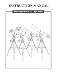
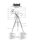
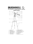
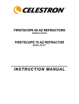
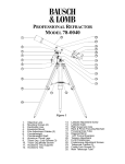
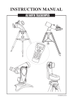
INSTRUCTION MANUAL
REFRACTORS/REFLECTORS WITH ALT-AZIMUTH MOUNT
090103V2
AZ1 & AZ2 MOUNTS
Refractor/AZ2
B
C
D
G
AZ2
F E
A
A. Dust Cap / Mask
(Remove before Viewing)
B. Dew Cap / Sun Shade
C. Objective Lens
D. Telescope Main Tube
E. Finderscope
F. Finderscope Bracket
G. Alignment Screws
H. Focus Locking Screw
I. Eyepiece
J. Diagonal
K. Focus Tube
L. Focus Knob
H
I
5
Reflector/AZ1
4
1
J
K
2
3
E
L
F
1. Altitude fine-adjustment
control
2. Azimuth Lock
3. Yoke Mount
4. Altitude Lock Knob
5. Yoke Locking Knob
D
a
G
C
H
B
I
a. Accessory Tray
b. Tripod Leg
c. Height Adjustment
Clamp
b
A
c
5
J
4
3
2
1
AZ1
a
b
c
A. Secondary Mirror Position
B. Dust Cap / Mask
(Remove before Viewing)
C. Focus Tube
D. Finderscope Bracket
E. Finderscope
F. Finderscope Adjustment
Screws
G. Eyepiece
H. Focus Knob
I. Telescope Main Tube
J. Primary Mirror Position
1. Yoke Locking Knob
2. Altitude Lock Knob
3. Azimuth Lock Knob
4. Yoke
5. Altitude Fine Adjustment
Control
a. Accessory Tray
b. Tripod Leg
c. Height Adjustment
Clamp
AZ3 MOUNTS
AZ3
B
A
C
D
F
G
E
H
I
J
4
K
L
3
1
A. Dust Cap / Mask
(Remove before Viewing)
B. Dew Cap / Sun Shade
C. Objective Lens
D. Piggyback Bracket
E. Telescope Main Body
F. Finderscope
G. Finderscope Bracket
H. Alignment Screws
I. Focus Tube
j. Eyepiece
K. Diagonal
L. Focus Knob
1. Azimuth Flexible Control
Cable
2. Altitude Flexible Control
Cable
3. Azimuth Adjustment Knob/
4. Tube Rings
a. Accessory Tray
b. Tripod Leg
c. Height Adjustment Clamp
2
a
b
c
Optional Multi-function
Plate
Red Dot Finder
3
TABLE OF CONTENTS
Assembling Your Telescope
5
For AZ1 & AZ2
Tripod Set up
Telescope Assembly
Finderscope Assembly
Eyepiece Assembly
5
5
6
6
For AZ3
Tripod Set up
Telescope Assembly
Finderscope/Red Dot FinderAssembly
Eyepiece Assembly
7
7
8
8
Operating Your Telescope
9
Aligning the Finderscope
Using the Red Dot Finder
Operating the AZ1/AZ2 Mount
Operating the AZ3 Mount
Using the Barlow Lens
Focusing
Using the Camera Adapter Tube
Pointing Your Telescope
Calculating the Magnification (power)
Calculating the Field of View
Calculating the Exit Pupil
Observing the Sky
9
9
10
10
10
10
11
11
12
12
12
13
Sky Conditions
Selecting an Observing Site
Choosing the Best Time to Observe
Chooling the Telescope
Adapting Your Eyes
13
13
13
13
13
Proper Care for Your Telescope
14
Collimating a Newtonian
Cleaning Your Telescope
14
15
Before you begin
This instruction manual is applicable to all the
models listed on the cover. Take a moment to
find the model closest to your telescope on p.2
and p.3. Follow the instructions for your specific
model in the manual. Read the entire
instructions carefully before beginning. Your
telescope should be assembled during daylight
hours. Choose a large, open area to work to
allow room for all parts to be unpacked.
Caution!
NEVER USE YOUR TELESCOPE TO LOOK
DIRECTLY AT THE SUN. PERMANENT EYE
DAMAGE WILL RESULT. USE A PROPER SOLAR
FILTER FOR VIEWING THE SUN. WHEN
OBSERVING THE SUN, PLACE A DUST CAP
OVER YOUR FINDERSCOPE TO PROTECT IT
FROM EXPOSURE. NEVER USE AN EYEPIECETYPE SOLAR FILTER AND NEVER USE YOUR
TELESCOPE TO PROJECT SUNLIGHT ONTO
ANOTHER SURFACE, THE INTERNAL HEAT
BUILD-UP WILL DAMAGE THE TELESCOPE
OPTICAL ELEMENTS.
FOR AZ1 & AZ2
TRIPOD SET UP
Fig.1
ADJUSTING TRIPOD LEGS (Fig.1)
1) Slowly loosen the height adjustment clamp and
gently pull out the lower section of each tripod leg.
Tighten the clamps to hold the legs in place.
2) Spread the tripod legs apart to stand the tripod upright.
3) Adjust the height of each tripod leg until the
tripod head is properly leveled. Note that the
tripod legs may not be at same length when
the equatorial mount is level.
Fig.2
ATTACHING THE ACCESSORY TRAY (Fig. 2)
1) Place the accessory tray on top of the bracket, and
secure with the locking knob from underneath.
TELESCOPE ASSEMBLY
Fig.3
AZ2 (refractor)
AZ1 (reflector)
Fig.4
Fig.4
ATTACHING TELESCOPE MAIN
TUBE TO MOUNT (Fig. 3, 4, 5, 6)
Fig.5
1) Unscrew the machine screw on
the altitude control locking knob.
2) Insert the micro-adjustable altitude
control into the hole on the side of
the altitude control locking knob.
3) Slide telescope tube into slots
on end of yoke mount. Secure
telescope tube onto yoke mount
using the yoke locking knobs
without overtightening.
4) Remove machine screw from
telescope tube and use this
to fasten the micro-adjustable
altitude control.
Fig.5
Fig.6
Fig.6
5
Fig.3
FINDERSCOPE ASSEMBLY
AZ2 (refractor)
AZ1 (reflector)
Fig.7
Fig.7
ATTACHING THE FINDERSCOPE
(Fig. 7, 8)
1) Locate finderscope optical assembly.
2) Remove the two knurled thumbscrews
near the end of the telescope main tube.
3) Position the finderscope bracket over
the screws in the telescope main body.
4) Secure the finderscope bracket with the
two knurled thumbscrews.
Fig.8
Fig.8
EYEPIECE ASSEMBLY
AZ2 (refractor)
AZ1 (reflector)
INSERTING EYEPIECE (Fig. 9)
1) Unscrew the thumbscrews on the end of the focus
tube to remove the plastic endcap.
2) Insert diagonal and re-tighten thumbscrews
to hold diagonal in place.
3) Loosen the thumbscrews on the diagonal.
4) Insert the desired eyepiece into diagonal
and secure by re-tightening
thumbscrews.
INSERTING EYEPIECE
(Fig. 9)
Fig.9
1) Unscrew the thumbscrews
on the end of the focus
tube to remove the black
plastic end-cap.
2) Insert the desired eyepiece
and re-tighten thumb
screws to hold eyepieces
in place.
Fig.9
6
FOR AZ3
TRIPOD SET UP
Fig.1
ADJUSTING TRIPOD LEGS (Fig.1)
1) Slowly loosen the height adjustment clamp and
gently pull out the lower section of each tripod leg.
Tighten the clamps to hold the legs in place.
2) Spread the tripod legs apart to stand the tripod upright.
3) Adjust the height of each tripod leg until the
tripod head is properly leveled. Note that the
tripod legs may not be at same length when
the equatorial mount is level.
Fig.2
ATTACHING THE ACCESSORY TRAY (Fig. 2)
1) Place the accessory tray on top of the bracket, and
secure with the locking knob from underneath.
TELESCOPE ASSEMBLY
Without multi-function plate
Fig.3
With multi-function plate
ATTACHING THE TUBE
RINGS TO MOUNT(Fig.3)
ATTACHING THE TUBE
RINGS TO MOUNT(Fig.3)
1) Remove the tube rings-multifunction
plate assembly from telescope
by releasing their thumbnuts
and opening their hinges.
2) Using one of the three threaded
holes in the multi-function plate
ring-plate assembly to the
mounting plateform. Turn the
knurled black wheel directly
underneath the mounting
platform on the alt-az mount
while holding the tube rings
in place to secure the
telescope in place.
1) Remove the tube rings from
telescope by releasing their
thumb nuts and opening
their hinges.
2) Fasten the tube rings to the
mount using the wench
provided.
ATTACHING THE TELESCOPE
MAIN TUBE TO TUBE
RINGS (Fig.4)
Fig.3
Fig.4
ATTACHING THE TELESCOPE
MAIN TUBE TO TUBE
RINGS (Fig.4)
1) Find the center of balance
of the telescope tube. Place
this in between the two tube
rings. Close the hinges
around the telescope and
fasten securely by tightening
the thumb nuts. Do not overtighten the thumb nuts.
1) Remove the telescope tube
from the paper covering.
2) Place telescope tube in
between the two tube rings.
Close the hinges around the
telescope and fasten securely
by tightening the thumb nuts
without over-tightening.
7
Fig.4
TELESCOPE ASSEMBLY
Fig.5
INSTALLING CONTROL CABLES (Fig.5)
1) Slide the sleeve end of the cable over the nipple
on the end of the worm gear. Secure the cable by tightening
the set screw against the flat surface on the nipple.
FINDERSCOPE/RED DOT FINDER ASSEMBLY
Fig.6
Small finderscope
Large finderscope / Red dot finder
ATTACHING THE FINDERSCOPE (Fig.6)
ATTACHING THE FINDERSCOPE
BRACKET / RED DOT FINDER (Fig.6)
1) Locate finderscope optical
assembly.
2) Remove the two knurled
thumbscrews near the end
of the telescope main body.
3) Position the finderscope
bracket over the screws in
the telescope main body.
4) Secure the finderscope
bracket with the two knurled
thumbscrews.
1) (For finderscope only): Locate the finderscope
bracket and carefully remove the rubber-o-ring
from it. Position the o-ring into groove on the
finderscope tube.
2) Slide finderscope assembly/ red dot finder into the
rectangular slot and tighten the thumbscrew to
hold the bracket in place.
Fig.6
EYEPIECE ASSEMBLY
INSERTING DIAGONAL AND EYEPIECE (Fig.7)
Fig.7
1) Loosen the thumbscrew on the end
of the focus tube.
2) Insert a diagonal into the focus tube and
re-tighten the thumbscrew to hold the
diagonal in place.
3) Loosen the thumbscrews on the diagonal.
4) Insert the desired eyepiece into the diagonal
and secure by re-tightening the thumbscrews.
8
OPERATING YOUR TELESCOPE
Aligning the finderscope
Fig.b
Fig.a
Fig.c
These fixed magnification scopes mounted on the optical tube are
very useful accessories. When they are correctly aligned with the
telescope, objects can be quickly located and brought to the centre
of the field. Alignment is best done outdoors in day light when it's
easier to locate objects. If it is necessary to refocus your
finderscope, sight on an object that is at least 500 yards (metres)
away. For 5x24 and 6x24 finderscope: twist the end of the
finderscope until focus is reached (Fig.a). For 6x30 finderscope:
loosen the locking ring by unscrewing it back towards the bracket.
The front lens holder can now be turned in and out to focus. When
focus is reached, lock it in position with the locking ring (Fig.b).
1. Choose a distant object that is at least 500 yards away and point
the main telescope at the object. Adjust the telescope so that the
object is in the centre of the view in your eyepiece.
Fig.d
2. Check the finderscope to see if the object centred in the main
telescope view is centred on the crosshairs.
3. For the 5x24 finderscope, use the three alignment screws to
centre the finderscope crosshairs on the object (Fig.c). For the
6x30 finderscope with spring loading, adjust only the two small
screws (Fig.d).
Using the Red Dot Finder
Fig.e
The Red Dot Finder is a zero magnification pointing tool that
uses a coated glass window to superimpose the image of a
small red dot onto the night sky. The Red Dot Finder is
equipped with a variable brightness control, azimuth
adjustment control, and altitude adjustment control (Fig.e). The
Red Dot Finder is powered by a 3-volt lithium battery located
underneath at the front. To use the Finder, simply look through
the sight tube and move your telescope until the red dot
merges with the object. Make sure to keep both eyes open
when sighting.
ON/OFF
Brightness
Control
Azimuth
adjustment
control
Sight Tube
Altitude
Adjustment
Control
Battery cover
Aligning the Red Dot Finder
Like all finderscopes, the Red Dot Finder must be properly aligned with
the main telescope before use. This is a simple process using the
azimuth and altitude control knobs.
Fig.f
1. Open the battery cover by pulling it down (you can gently pry at the 2
small slots) and remove the plastic shipping cover over the battery
(Fig.f).
2. Turn on the Red Dot Finder by rotating the variable brightness control
clockwise until you hear a "click". Continue rotating the control knob
to increase the brightness level.
3. Insert a low power eyepiece into the telescope's focuser. Locate a
bright object and position the telescope so that the object is in the
centre of the field of view.
4. With both eyes open, look through the sight tube at the object. If the
red dot overlaps the object, your Red Dot Finder is perfectly aligned.
If not, turn its azimuth and altitude adjustment controls until the red
dot is merged with the object.
9
Plastic
shipping
cover
Fig.g
Operating the AZ1/AZ2 mount
Altitude adjustment
This telescope has an altitude(up-down)-azimuth(left-right)
mount to control telescope movements. Loosen the azimuth
lock knob to make left-right direction movements then tighten
to lock. Loosen the altitude lock knob to make course up-down
changes. Altitude fine adjustments can be made by rotating
the knurled wheel on the altitude fine adjustment rod after
tightening the altitude lock knob. (AZ1: Fig.g, AZ2: Fig.h)
Altitude fine
adjustment
Azimuth adjustment
Fig.h
Operating the AZ3 mount
Altitude adjustment
This mount has controls for movement in altitude (up-down) and
azimuth (left-right). Coarse azimuth movement is controlled by a
locking knob located near the tripod head for left-right rotation.
Loosen the knob to make large direction changes then lock it
for fine adjustments. Coarse Altitude movement is controlled by
a friction bolt. Use the micro-adjustment control cables to make
small altitude and azimuth movements such as centreing
objects in view. The micro-adjustment controls have limited
travel so it is best to centre them on their threads before making
a coarse adjustment (Fig.i).
Altitude fine
adjustment
Azimuth adjustment
Fig.i
Azimuth locking knob
Altitude fine adjustment
Using the Barlow lens
A Barlow is a negative lens which increases the magnifying
power of an eyepiece, while reducing the field of view. It
expands the cone of the focussed light before it reaches the
focal point, so that the telescope's focal length appears longer
to the eyepiece.
Azimuth fine adjustment
Fig.j
The Barlow is inserted between the focuser and the eyepiece
in a reflector, and usually between the diagonal and the
eyepiece in a refractor or a catadioptric (Fig.j). With some
telescopes, it can also be inserted between the focuser and
the diagonal, and in this position it gives even greater
magnification. For example, a 2X Barlow when inserted after
the diagonal can become 3X when placed in front of the
diagonal.
Eyepiece
Barlow
Diagonal
(Refracting Telescopes)
Barlow
In addition to increasing magnification, the benefits of using a
Barlow lens include improved eye relief, and reduced
spherical aberration in the eyepiece. For this reason, a
Barlow plus a lens often outperform a single lens producing
the same magnification. However, it is greatest value may be
that a Barlow can potentially double the number of eyepiece
in your collection.
(Reflecting Telescopes)
Focusing
Fig.k
Slowly turn the focus knobs (Fig.k), one way or the other, until
the image in the eyepiece is sharp. The image usually has to
be finely refocused over time, due to small variations caused
by temperature changes, flexures, etc. This often happens
with short focal ratio telescopes, particularly when they
haven't yet reached outside temperature. Refocusing is almost
always necessary when you change an eyepiece or add or
remove a Barlow lens.
10
Eyepiece
Using the Camera Adapter Tube
When you connect a camera directly to your telescope for "prime focus" photography, you sometimes require
an adapter so that the camera can be focussed. Some reflectors need more length than the focuser can travel,
in order to focus the camera, and some refractors are designed to be used with diagonals, so when used with
only a camera, their focal length has to be extended. This is particularly true when photographing near objects.
Your camera with its telescope "lens" may focus on a distant object such as a star, but will require the 2.5"
camera adapter tube to focus on a near object such as a bird.
The camera adapter tube is easily installed by
screwing it onto the T-threads of the eyepiece
holder, then screwing the specific T-adapter ring
for your camera (optional) onto the T-threads on
the other end of the camera adapter tube (Fig.l).
This makes the telescope into a "lens" which you
then attach to your camera as you would any
other lens.
Fig.l
Focuser
Eyepiece
Holder
Camera Adapter T-adapter
Tube
Camera
Pointing your telescope
Pointing an altitude-azimuth (alt-az) mounted telescope is relatively easy. With the mount level, you can
swivel the telescope around on a plane parallel to your horizon and then tilt it up and down from there
(Fig.c). You can think of it as turning your telescope in azimuth until it is facing the horizon below a celestial
object and then tilting it up to the object's altitude. However, the Earth rotates and therefore the stars are
constantly moving, so to track with this mount you need to constantly nudge the optical tube in both
azimuth and altitude to keep the object in the field.
In reference material for your local position, the altitude will be listed as ±degrees (minutes, seconds)
above or below your horizon. Azimuth may be listed by the cardinal compass points such as N, SW, ENE,
etc., but it is usually listed in 360 degree (minutes, seconds) steps clockwise from North (0°), with East,
South and West being 90°, 180° and 270 °, respectively (Fig.m).
Zenith
Fig.m
Meridian
Line
(270°)
Tilt in
Altitude
W
N (0°/360°)
(90°)
Nadir
(180°)
S
E
Nadir
11
Rotate in Azimuth
Calculating the magnification (Power)
The magnification produced by a telescope is determined by the focal length of the eyepiece that is used
with it. To determine a magnification for your telescope, divide its focal length by the focal length of the
eyepieces you are going to use. For example, a 10mm focal length eyepiece will give 80X magnification with
an 800mm focal length telescope.
Focal length of the telescope
magnification =
800mm
=
Focal length of the eyepiece
10mm
= 80X
When you are looking at astronomical objects, you are looking through a column of air that reaches to the
edge of space and that column seldom stays still. Similarly, when viewing over land you are often looking
through heat waves radiating from the ground, house, buildings, etc. Your telescope may be able to give
very high magnification but what you end up magnifying is all the turbulence between the telescope and the
subject. A good rule of thumb is that the usable magnification of a telescope is about 2X per mm of aperture
under good conditions.
Calculating the field of view
The size of the view that you see through your telescope is called the true (or actual) field of view and it is
determined by the design of the eyepiece. Every eyepiece has a value, called the apparent field of view,
which is supplied by the manufacturer. Field of view is usually measured in degrees and/or arc-minutes
(there are 60 arc-minutes in a degree). The true field of view produced by your telescope is calculated by
dividing the eyepiece's apparent field of view by the magnification that you previously calculated for the
combination. Using the figures in the previous magnification example, if your 10mm eyepiece has an
apparent field of view of 52 degrees, then the true field of view is 0.65 degrees or 39 arc-minutes.
Apparent Field of View
True Field of View =
Magnification
=
52°
80X
= 0.65°
To put this in perspective, the moon is about 0.5° or 30 arc-minutes in diameter, so this combination would
be fine for viewing the whole moon with a little room to spare. Remember, too much magnification and too
small a field of view can make it very hard to find things. It is usually best to start at a lower magnification
with its wider field and then increase the magnification when you have found what you are looking for. First
find the moon then look at the shadows in the craters!
Calculating the exit pupil
The Exit Pupil is the diameter (in mm) of the narrowest point of the cone of light leaving your telescope.
Knowing this value for a telescope-eyepiece combination tells you whether your eye is receiving all of the
light that your primary lens or mirror is providing. The average person has a fully dilated pupil diameter of
about 7mm. This value varies a bit from person to person, is less until your eyes become fully dark adapted
and decreases as you get older. To determine an exit pupil, you divide the diameter of the primary of your
telescope (in mm) by the magnification.
Diameter of Primary mirror in mm
Exit Pupil =
Magnification
For example, a 200mm f/5 telescope with a 40mm eyepiece produces a magnification of 25x and an exit
pupil of 8mm. This combination can probably be used by a young person but would not be of much value to
a senior citizen. The same telescope used with a 32mm eyepiece gives a magnification of about 31x and an
exit pupil of 6.4mm which should be fine for most dark adapted eyes. In contrast, a 200mm f/10 telescope
with the 40mm eyepiece gives a magnification of 50x and an exit pupil of 4mm, which is fine for everyone.
12
OBSERVING THE SKY
Sky conditions
Sky conditions are usually defined by two atmospheric characteristics, seeing, or the steadiness of the air,
and transparency, light scattering due to the amount of water vapour and particulate material in the air.
When you observe the Moon and the planets, and they appear as though water is running over them, you
probably have bad "seeing" because you are observing through turbulent air. In conditions of good "seeing",
the stars appear steady, without twinkling, when you look at them with unassisted eyes (without a
telescope). Ideal "transparency" is when the sky is inky black and the air is unpolluted.
Selecting an observing site
Travel to the best site that is reasonably accessible. It should be away from city lights, and upwind from any
source of air pollution. Always choose as high an elevation as possible; this will get you above some of the
lights and pollution and will ensure that you aren't in any ground fog. Sometimes low fog banks help to block
light pollution if you get above them. Try to have a dark, unobstructed view of the horizon, especially the
southern horizon if you are in the Northern Hemisphere and vice versa. However, remember that the
darkest sky is usually at the "Zenith", directly above your head. It is the shortest path through the
atmosphere. Do not try to observe any object when the light path passes near any protrusion on the ground.
Even extremely light winds can cause major air turbulence as they flow over the top of a building or wall. If
you try to observe on any structure, or even a sidewalk, movements you make may cause the telescope to
vibrate. Pavement and concrete can also radiate stored heat which will affect observing.
Observing through a window is not recommended because the window glass will distort images
considerably. And an open window can be even worse, because warmer indoor air will escape out the
window, causing turbulence which also affects images. Astronomy is an outdoor activity.
Choosing the best time to observe
The best conditions will have still air, and obviously, a clear view of the sky. It is not necessary that the sky be
cloud-free. Often broken cloud conditions provide excellent seeing. Do not view immediately after sunset.
After the sun goes down, the Earth is still cooling, causing air turbulence. As the night goes on, not only will
seeing improve, but air pollution and ground lights will often diminish. Some of the best observing time is often
in the early morning hours. Objects are best observed as they cross the meridian, which is an imaginary line
that runs through the Zenith, due North-South. This is the point at which objects reach their highest points in
the sky. Observing at this time reduces bad atmospheric effects. When observing near the horizon, you look
through lots of atmosphere, complete with turbulence, dust particles and increased light pollution.
Cooling the telescope
Telescopes require at least 10 to 30 minutes to cool down to outside air temperature. This may take longer if
there is a big difference between the temperature of the telescope and the outside air. This minimizes heat
wave distortion inside telescope tube (tube currents). Allow a longer cooling time for larger optics. If you are
using an equatorial mount, use this time for polar alignment.
Adapting your eyes
Do not expose your eyes to anything except red light for 30 minutes prior to observing. This allows your
pupils to expand to their maximum diameter and build up the levels of optical pigments, which are rapidly
lost if exposed to bright light. It is important to observe with both eyes open. This avoids fatigue at the
eyepiece. If you find this too distracting, cover the non-used eye with your hand or an eye patch. Use
averted vision on faint objects: The center of your eye is the least sensitive to low light levels. When viewing
a faint object, don't look directly at it. Instead, look slightly to the side, and the object will appear brighter.
13
PROPER CARE FOR YOUR TELESCOPE
Collimating a Newtonian
Fig.n
Collimation is the process of aligning the mirrors of
your telescope so that they work in concert with each
other to deliver properly focused light to your eyepiece.
By observing out-of-focus star images, you can test
whether your telescope's optics are aligned. Place a
star in the centre of the field of view and move the
focuser so that the image is slightly out of focus. If the
seeing conditions are good, you will see a central circle
of light (the Airy disc) surrounded by a number of
diffraction rings. If the rings are symmetrical about the
Airy disc, the telescope's optics are correctly collimated
(Fig.n).
If you do not have a collimating tool, we suggest that
you make a "collimating cap" out of a plastic 35mm film
canister (black with gray lid). Drill or punch a small
pinhole in the exact center of the lid and cut off the
bottom of the canister. This device will keep your eye
centered of the focuser tube. Insert the collimating cap
into the focuser in place of a regular eyepiece.
Correctly aligned
Needs collimation
Fig.o
Focuser
Support for
secondary mirror
Primary mirror
Secondary mirror
Fig.p
Collimation is a painless process and works like this:
Primary
mirror
Pull off the lens cap which covers the front of the
telescope and look down the optical tube. At the bottom
you will see the primary mirror held in place by three
clips 120º apart, and at the top the small oval
secondary mirror held in a support and tilted 45º toward
the focuser outside the tube wall (Fig.o).
The secondary mirror is aligned by adjusting the three
smaller screws surrounding the central bolt. The
primary mirror is adjusted by the three adjusting screws
at the back of your scope. The three locking screws
beside them serve to hold the mirror in place after
collimation. (Fig.p)
Mirror cell
Locking screw
Adjusting screw
Fig.q
Primary mirror clip
Aligning the Secondary Mirror
Point the telescope at a lit wall and insert the
collimating cap into the focuser in place of a regular
eyepiece. Look into the focuser through your collimating
cap. You may have to twist the focus knob a few turns
until the reflected image of the focuser is out of your
view. Note: keep your eye against the back of the focus
tube if collimating without a collimating cap. Ignore the
reflected image of the collimating cap or your eye for
now, instead look for the three clips holding the primary
mirror in place. If you can't see them (Fig.q), it means
that you will have to adjust the three bolts on the top of
the secondary mirror holder, with possibly an Allen
wrench or Phillip's screwdriver. You will have to
alternately or loosen one and then compensate for the
slack by tightening the other two. Stop when you see all
three mirror clips (Fig.r). Make sure that all three small
alignment screws are tightened to secure the
secondary mirror in place.
Fig.r
Primary mirror clip
Ignore the reflected
image for now
Primary mirror clip
Primary mirror clip
14
Aligning the Primary Mirror
Find the three locking screws at the back of your telescope and loosen them by a few turns.
Adjusting screw
Locking screw
Locking screw
Adjusting screw
If you see 3 large nuts protruding
from the back of your telescope
and 3 small Phillip's-head screws
besides them, the Phillip's-head
screws are the locking screws
and the large nuts are the
adjusting screws.
hex bolt (Locking screw)
If you see 6 Phillip's-head
screws but 3 protruding from
the back of your telescope, the
3 protruding screws are
locking screws and the ones
next to them are adjusting
screws.
Adjusting screw
If you see 3 hex bolts and 3 Phillip's head
screws, the hex bolts are the locking
screws and the Phillip's-head screws are
the adjusting screws. You will need an
Allen wrench to adjust the locking screws.
Now run your hand around the front of your
telescope keeping your eye to the focuser, you
will see the reflected image of your hand. The
idea here being to see which way the primary
mirror is defected, you do this by stopping at the
point where the reflected image of the secondary
mirror is closest to the primary mirrors' edge
(Fig.s).
Fig.s
Secondary
mirror
When you get to that point, stop and keep your
hand there while looking at the back end of your
telescope, is there a adjusting screw there? If
there is you will want to loosen it (turn the screw
to the left) to bring the mirror away from that
point. If there isn't a adjusting screw there, then
go across to the other side and tighten the
adjusting screw on the other side. This will
gradually bring the mirror into line until it looks
like Fig.t. (It helps to have a friend to help for
primary mirror collimation. Have your partner
adjust the adjusting screws according to your
directions while you look in the focuser.)
Primary mirror
stop and keep your
hand here
Fig.t
After dark go out and point your telescope at
Polaris, the North Star. With an eyepiece in the
focuser, take the image out of focus. You will see
the same image only now, it will be illuminated by
starlight. If necessary, repeat the collimating
process only keep the star centered while
tweaking the mirror.
Both mirrors aligned
with collimating cap in
Cleaning your telescope
Both mirrors aligned with
eye looking in focuser
Replace the dust cap over end of telescope whenever not in use. This prevents dust from settling on mirror
or lens surface. Do not clean mirror or lens unless you are familiar with optical surfaces. Clean finderscope
and eyepieces with special lens paper only. Eyepieces should be handled with care, avoid touching optical
surfaces.
15
CAUTION!
NEVER USE YOUR TELESCOPE TO LOOK DIRECTLY AT THE SUN.
PERMANENT EYE DAMAGE WILL RESULT. USE A PROPER SOLAR FILTER
FIRMLY MOUNTED ON THE FRONT OF THE TELESCOPE FOR VIEWING
THE SUN. WHEN OBSERVING THE SUN, PLACE A DUST CAP OVER YOUR
FINDERSCOPE OR REMOVE IT TO PROTECT YOU FROM ACCIDENTAL
EXPOSURE. NEVER USE AN EYEPIECE-TYPE SOLAR FILTER AND NEVER
USE YOUR TELESCOPE TO PROJECT SUNLIGHT ONTO ANOTHER
SURFACE, THE INTERNAL HEAT BUILD-UP WILL DAMAGE THE
TELESCOPE OPTICAL ELEMENTS.