1
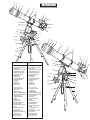
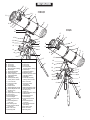
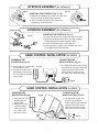
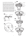
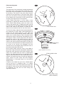
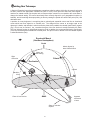
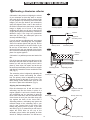
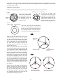
Telescopes with HEQ5 & EQ6 Mount
110203V1
A
B
C
REFRACTOR
D
E
F
G
H
I
J
17
K
16
L
15
14
13
1
N
M
2
3
4
12
11
A
B
5
10
C
6
D
E
F
9
G
8
7
H
I
J
17
HEQ5
A. Dust Cap/Mask
EQ6
16
15
A. Dust Cap/Mask
(Remove before Viewing)
(Remove before Viewing)
B. Sun Shade
C. Objective Lens Location
D. Adjustable Lens Cell
E. Telescope Main Body
F. Piggyback Bracket
G. Tube Ring
H. Finderscope
I. Finderscope Bracket
J. Alignment Screw
K. Eyepiece
L. Diagonal
M. Focus Tube
N. Focus Knob
B. Sun Shade
C. Objective Lens Location
D. Adjustable Lens Cell
E. Telescope Main Body
F. Piggyback Bracket
G. Tube Ring
H. Finderscope
I. Finderscope Bracket
J. Alignment Screw
K. Eyepiece
L. Diagonal
M. Focus Tube
N. Focus Knob
1. R.A. Lock Lever
2. Polarscope Holder
(not shown)
3. Latitude Scale
4. Altitude Adjustment T-bolts
5. Azimuth Adjustment Knob
6. Accessory Tray
7. Height Adjustment
Clamp
8. Tripod Leg
9. Hand Control
10. Counterweight Rod
11. Counterweight
12. Counterweight Thumb
Screw
13. Counterweight Rod
Lock Knob
14. Dec Setting Circle
15. Dual Axis Motor Drives
(not shown)
16. Dec Lock Lever
17. Mounting Plate
1. R.A. Lock Lever
2. Polarscope Holder
(not shown)
3. Latitude Scale
4. Altitude Adjustment T-bolts
5. Azimuth Adjustment Knob
6. Accessory Tray
7. Tripod Leg
8. Height Adjustment
Clamp
9. Hand Control
10. Counterweight Rod
11. Counterweight
12. Counterweight Thumb
Screw
13. Counterweight Rod
Lock Knob
14. Dual Axis Motor Drives
(not shown)
15. Dec Setting Circle
16. Dec Lock Lever
17. Mounting Plate
K
14
1
2
13
12
3
4
11
5
10
6
9
7
8
2
N M
L
E
REFLECTOR
F G
H I
D
HEQ5
J
K
C
L
B
A
17
EQ6
16
E
F
15
G
1
14
2
13
12
3
D
4
C
H
I
J
5
11
K
L
B
10
A
6
9
17
7
HEQ5
A.
B.
C.
D.
E.
F.
G.
H.
I.
J.
K.
L.
Eyepiece
Focus Tube
Focus Knob
Dust Cap/Maks
(Remove before viewing)
Finderscope
Finderscope Bracket
Alignment Screw
Tension Adjustment Screw
Piggyback Bracket
Tube Rings
Telescope Main Body
Primary Mirror Location
1. R.A. Lock Lever
2. Polarscope Holder
(not shown)
3. Latitude Scale
4. Altitude Adjustment T-bolts
5. Azimuth Adjustment Knob
6. Accessory Tray
7. Tripod Leg
8. Height Adjustment Clamp
9. Hand Control
10. Counterweight Rod
11. Counterweight
12. Counterweight Thumb
Screw
13. Counterweight Rod
Lock Knob
14. Dec Setting Circle
15. Dual Axis Motor Drives
(not shown)
16. Dec Lock Level
17. Mounting Plate
EQ6
A.
B.
C.
D.
E.
F.
G.
H.
I.
J.
K.
L.
16
Eyepiece
Focus Tube
Focus Knob
Dust Cap/Maks
(Remove before viewing)
Finderscope
Finderscope Bracket
Alignment Screw
Tension Adjustment Screw
Piggyback Bracket
Tube Rings
Telescope Main Body
Primary Mirror Location
8
15
1
2
14
13
3
12
4
11
5
10
1. R.A. Lock Lever
2. Polarscope Holder
(not shown)
3. Latitude Scale
4. Altitude Adjustment T-bolts
5. Azimuth Adjustment Knob
6. Accessory Tray
7. Tripod Leg
8. Height Adjustment Clamp
9. Hand Control
10. Counterweight Rod
11. Counterweight
12. Counterweight Thumb
Screw
13. Counterweight Rod
Lock Knob
14. Dual Axis Motor Drives
(not shown)
15. Dec Setting Circle
16. Dec Lock Level
17. Mounting Plate
9
6
7
8
3
TABLE OF CONTENTS
Assembling Your Telescope
5
Tripod set up
Mount assembly
Telescope assembly
Finderscope assembly
Eyepiece assembly
Hand control installation
5
5
6
6
7
7
Operating Your Telescope
8
8
8
9
9
10
10
10
15
15
16
20
Aligning the finderscope
Balancing the telescope
Operating the HEQ5/EQ6 mount
Using the hand control
Using the optional Barlow lens
Focusing
The polarscope
Tracking celestial objects
Setting circles
Pointing your telescope
Choosing the appropriate eyepiece
Observing the Sky
21
Sky conditions
Selecting an observing site
Choosing the best time to observe
Chooling the telescope
Adapting your eyes
21
21
21
21
21
Proper Care for Your Telescope
22
Collimating a Newtonian reflector
Collimating a refractor (with the adjustable objective-lens cell)
Cleaning your telescope
Before you begin
This instruction manual is applicable to all the
models with the HEQ5 or EQ6 mount. Take a
moment to find the model closest to your
telescope on p.2 and p.3. Follow the
instructions for your specific model in the
manual. Read the entire instructions carefully
before beginning. Your telescope should be
assembled during daylight hours. Choose a
large, open area to work to allow room for all
parts to be unpacked.
22
24
24
Caution!
NEVER USE YOUR TELESCOPE TO LOOK
DIRECTLY AT THE SUN. PERMANENT EYE
DAMAGE WILL RESULT. USE A PROPER SOLAR
FILTER FOR VIEWING THE SUN. WHEN
OBSERVING THE SUN, PLACE A DUST CAP
OVER YOUR FINDERSCOPE TO PROTECT IT
FROM EXPOSURE. NEVER USE AN EYEPIECETYPE SOLAR FILTER AND NEVER USE YOUR
TELESCOPE TO PROJECT SUNLIGHT ONTO
ANOTHER SURFACE, THE INTERNAL HEAT
BUILD-UP WILL DAMAGE THE TELESCOPE
OPTICAL ELEMENTS.
ASSEMBLING YOUR TELESCOPE
TRIPOD SET UP
Fig. 1
ASSEMBLING THE TRIPOD LEGS (Fig.1)
1) Slowly loosen the height adjustment clamp
Fig. 2.
and gently pull out the lower section of
each tripod leg. Tighten the clamps to hold
the legs in place.
2) Spread the tripod legs apart to stand
the tripod upright.
3) Place a carpenter's level or bubble level on
the top of the tripod legs. Adjust the height of
each tripod leg until the tripod head is properly
leveled. Note that the tripod legs may not be at
same length when the equatorial mount is level.
ATTACHING MOUNT TO TRIPOD LEGS (Fig. 2)
1) Align metal dowel on the tripod head with the gap
between the azimuth adjustment knobs underneath
the mount.
2) Push the primary locking shaft up against the
mount and turn the knurled knob underneath to
secure mount to tripod.
Fig. 3
ATTACHING THE ACCESSORY TRAY (Fig. 3)
1) Slide the accessory tray along the primary locking
shaft until it pushes against the tripod legs.
2) Secure with the washer and locking knob.
Note: Loosen the azimuth adjustment knobs if mount does not
fit into tripod head completely. Retighten knobs to secure.
MOUNT ASSEMBLY
Fig. 4
EQ-6
INSTALLING THE COUNTERWEIGHTS (Fig. 4, 5)
1) Loosen the counterweight rod lock knob
and gently pull out the counterweight rod.
Re-tighten the lock knob to secure the
counterweight rod in place.
2) Unscrew the threaded cap from the
end of the counterweight rod.
3) Locate the counterweights and slide them
halfway along the counterweight rod. Tighten
the counterweight thumb screws to secure.
5) Replace the cap on the end of the
counterweight rod.
(diagram applicable to both mounts)
5
Fig. 5
TELESCOPE ASSEMBLY
Fig. 7
ATTACHING THE MOUNTING PLATE (Fig.6)
Fig. 6
1) Position the mounting plate on the mounting bracket.
2) Secure by tightening the two locking screws.
ATTACHING THE TUBE RINGS (Fig.7)
EQ-6
(diagram applicable to both mounts)
1) Remove the telescope tube assembly from
its plastic packaging.
2) Remove the tube rings from the telescope by
releasing their thumb nuts and opening
their hinges.
3) Using the bolts provided, fasten the tube rings
to the mount with the 10mm wrench provided.
TELESCOPE ASSEMBLY
Fig. 8
ATTACHING THE TELESCOPE MAIN TUBE TO THE
TUBE RINGS (Fig.8)
1) Remove the telescope tube from the paper covering.
2) Find the center of balance of the telescope tube. Place this in
between the two tube rings. Close the hinges around the
telescope and fasten securely by tightening the thumb nuts.
FINDERSCOPE ASSEMBLY (for reflectors)
Fig.9
ATTACHING THE FINDERSCOPE
BRACKET (Fig. 9,10,11)
Fig.10
Fig.11
1) Locate the finderscope bracket. Carefully remove
the rubber-o-ring from the finderscope bracket.
2) Position the o-ring into the groove located
approximately half-way along the finderscope tube.
3) Locate the finderscope optical assembly.
4) Slide the finderscope bracket into the rectangular
slot and tighten the screw to hold the mount in place.
5) Position the finderscope into its bracket by sliding
it backwards until the rubber o-ring seats in the
finderscope mount.
FINDERSCOPE ASSEMBLY (for refractors)
Fig.12
Fig.13
ATTACHING THE FINDERSCOPE (Fig.12,13,14)
1) Locate the finderscope bracket. Carefully remove
the rubber-o-ring from the finderscope bracket.
2) Position the o-ring into the groove located approximately
half-way along the finderscope tube.
3) Locate the finderscope optical assembly.
4) Slide the finderscope bracket into the rectangular slot and
tighten the screw to hold the mount in place.
5) Position the finderscope into its mount by sliding it backwards
until the rubber o-ring seats in the finderscope mount.
6
Fig.14
EYEPIECE ASSEMBLY (for reflectors)
Fig.15
Fig.16
INSERTING THE EYEPIECE (Fig.15, 16)
1) Unscrew the thumbscrews on the end of the focus
tube to remove the black plastic end-cap.
2) Insert the desired eyepiece and secure it by
retightening the thumbscrews.
EYEPIECE ASSEMBLY (for refractors)
INSERTING THE EYEPIECE (Fig.17)
Fig.17
1) Loosen the thumbscrew on the end of the focus tube.
2) Insert the diagonal into the focus tube and re-tighten
the thumbscrew to hold the diagonal in place.
3) Loosen the thumbscrews on the diagonal.
4) Insert the desired eyepiece into diagonal and secure
by re-tightening the thumbscrews.
HAND CONTROL INSTALLATION (for HEQ5)
CONNECTING THE
HAND CONTROL (Fig.19)
POWERING THE
EQ6 MOTORS (Fig.18)
1) Insert eight "D" cell batteries
into the battery case.
2) Plug the DC power cord
from battery case into the
DC 12V outlet on the side
of the mount.
1) The EQ6 hand control has a phone
type connector. Plug the phone jack
connector into the outlet on the
mount. Push the connector into
the outlet until it clicks into place.
Fig.18
Fig.19
HAND CONTROL INSTALLATION (for EQ6)
CONNECTING THE
HAND CONTROL (Fig.21)
Fig.20
DC
Po
we
r
1) Insert eight "D" cell
batteries into the
battery case.
2) Plug the DC power
cord from battery
case into the DC
12V outlet on the
side of the mount.
12V
POWERING THE
EQ6 MOTORS (Fig.20)
1) The EQ6 hand control has
a phone type connector.
Plug the phone jack connector
into the outlet on the mount.
Push the connector into the
outlet until it clicks into place.
Fig.21
7
OPERATING YOUR TELESCOPE
Aligning the finderscope
Fig.a
Fig.a-1
These fixed magnification scopes mounted on the optical tube are very useful
accessories. When they are correctly aligned with the telescope, objects can
be quickly located and brought to the centre of the field. Alignment is best
done outdoors in day light when it's easier to locate objects. If it is necessary
to refocus your finderscope, sight on an object that is at least 500 yards
(metres) away. Loosen the locking ring by unscrewing it back towards the
bracket. The front lens holder can now be turned in and out to focus. When
focus is reached, lock it in position with the locking ring (Fig.a).
1) Choose a distant object that is at least 500 yards away and
point the main telescope at the object. Adjust the telescope so
that the object is in the centre of the view in your eyepiece.
2) Check the finderscope to see if the object centred in the main
telescope view is centred on the crosshairs.
3) Adjust the two small screws to centre the finderscope
crosshairs on the object (Fig.a-1).
Balancing the telescope
A Telescope should be balanced before each observing session. Balancing reduces stress on the telescope
mount and allows for precise control of micro-adjustment. A balanced telescope is specially critical when
using the optional clock drive for astrophotography. The telescope should be balanced after all accessories
(eyepiece, camera, etc.) have been attached. Before balancing your telescope, make sure that your tripod is
balanced and on a stable surface. For photography, point the telescope in the direction you will be taking
photos before performing the balancing steps.
R.A. Balancing
Fig.b
1) For best results, adjust the altitude of the mount
to between 15º and 30º if possible, by using the
altitude adjustment T-bolt. It is important to loosen
one T-bolt before tightening the other. Overtigtening can cause the bolts to bend or break.
2) Slowly unlock the R.A. and Dec. lock knobs.
Rotate the telescope until both the optical tube
and the counterweight rod are horizontal to the
ground, and the telescope tube is to the side of
the mount (Fig.b).
3) Tighten the Dec. lock knob.
4) Move the counterweights along the counterweight
rod until the telescope is balanced and remains
stationary when released.
5) Tighten the counterweight thumb screws to hold
the counterweights in their new position.
N
(diagram applicable to both mounts)
Dec. Balancing
The R.A. balancing should be done before proceeding with Dec. balancing.
1) For best results, adjust the altitude of the mount to between 60º and 75º if possible.
2) Release the R.A. lock knob and rotate around the R.A. axis so that the counterweight rod is in a horizontal
position. Tighten the R.A. lock knob.
3) Unlock the Dec. lock knob and rotate the telescope tube until it is parallel to the ground.
4) Slowly release the telescope and determine in which direction it rotates. Loosen the telescope tube rings and
slide the telescope tube forward or backward in the rings until it is balanced.
5) Once the telescope no longer rotates from its parallel starting position, re-tighten the tube rings and the Dec.
lock knob. Reset the altitude axis to your local latitude.
8
Fig.c
Operating the HEQ5/EQ6 mount
The EQ6 mount has controls for both conventional altitude (up-down)
and azimuthal (left-right) directions of motion. Use the altitude
adjustment T-bolts for altitude adjustments. The two T-bolts work
against each other to move the mount in altitude or azimuth. It is
important to loosen one T-bolt before tightening the other. Overtigtening can cause the bolts to bend or break. The azimuthal axis is
changed by the two azimuth adjustment knobs located near the tripod
head. These provide fine-adjustment of azimuth for polar aligning
(Fig.c).
In addition, this mount has direction controls for polar aligned
astronomical observing. These directions use Right Ascension
(east/west) and Declination (north/south) axis. There are two options
to move the telescope in these directions: For large and quick
movement, loosen the R.A. lock lever or the Dec. lock lever (Fig.c-1).
For fine adjustments, use the motor drive hand control (see "Using
the Hand Control").
Altitude
adjustment
EQ-6
Azimuth
adjustment
(This diagram is applicable to both mounts)
Fig.c-1
HEQ5
Dec. adjustment
R.A. adjustment
There are three numerical scales on this mount. The lower scale on
the side of the mount is used for polar alignment of the telescope to
your local latitude. The R.A. (Right Ascension) scale measures hour
angle and is adjustable to your local meridian. The declination scale is
located near the top (EQ6) or the counterweight rod (HEQ5) of the
mount.
Latitude
scale
Using the hand control
The N/Off/S switch acts as a power switch as well as controller for
the directions of the motors. The "N" position allows R.A. motor to
track for the Northern Hemisphere observations and the "S" position
is suitable for the Southern Hemisphere (Fig.d). When the EQ6 Hand
Control is turned on and all buttons are depressed, the R.A. motor
will rotate at the proper speed to compensate for the earth's rotation.
The Dec. axis does not automatically rotate. When the mount is
correctly polar aligned, you only need to turn the R.A. slow-motion to
follow or track objects as they move through the field. The Dec.
control is not needed for tracking.
The four push buttons control the directions of the motors. The updown buttons control the declination motor while the left-right buttons
change the R.A. axis.
Fig.d
Power/direction
switch
R.A control
The rate switch allows for changes to the speed rate of the motors buttons
from high speed slew rate (16X or fast) to slow micro-adjustment
(2X) and the speed in between (8X). When the rate switch is set on
"2X", pressing the right R.A. button will rotate the telescope forward at
Fig.d-1
twice the tracking speed or approximately ½º per minute. The left
R.A. button stops all motion and allows stars to drift by at their
normal rotation rate of approx. ¼º per minute. The "8X" setting moves
the telescope forward at 8 times the tracking rate and the left button
moves the telescope backwards at 7 times the tracking rate. The
"Fast" or "16X" setting allows forward at 16 times the tracking rate and
the left button moves the telescope backwards at 15 times the
tracking rate. When the reverse switches on the side of the hand
control are set on "REV" (Fig.d-1), the four push buttons act in
reverse. For example, when the upper switch is set to "REV",
pressing the left R.A. button moves the telescope forward, and the
right R.A. button moves the telescope backwards.
9
Rate switch
2X
8X
Fast
N
OFF
S
(or 16X)
Dec control
buttons
Dec
R.A
R.A
Dec
RA
REV
DEC
REV
Reverse
switches
Using the optional Barlow lens
Fig.e
A Barlow is a negative lens which increases the
magnifying power of an eyepiece, while reducing the field
of view. It expands the cone of the focussed light before it
reaches the focal point, so that the telescope's focal length
appears longer to the eyepiece.
Eyepiece
Barlow
Diagonal
The Barlow is inserted between the focuser and the
eyepiece in a reflector, and usually between the diagonal
and the eyepiece in a refractor or a maksutov (Fig.e). With
some telescopes, it can also be inserted between the
focuser and the diagonal, and in this position it gives even
greater magnification. For example, a 2X Barlow when
inserted after the diagonal can become 3X when placed in
front of the diagonal.
(Refracting Telescopes
and Maksutovs)
Barlow
In addition to increasing magnification, the benefits of
using a Barlow lens include improved eye relief, and
reduced spherical aberration in the eyepiece. For this
reason, a Barlow plus a lens often outperform a single lens
producing the same magnification. However, its greatest
value may be that a Barlow can potentially double the
number of eyepieces in your collection.
Eyepiece
(Reflecting Telescopes)
Focusing
Fig.f
Slowly turn the focus knobs under the focuser, one way or
the other, until the image in the eyepiece is sharp (Fig.f).
The image usually has to be finely refocused over time,
due to small variations caused by temperature changes,
flexures, etc. This often happens with short focal ratio
telescopes, particularly when they have not yet reached
outside temperature. Refocusing is almost always
necessary when you change an eyepiece or add or
remove a Barlow lens. On some focusers, there is a
tension adjustment. Over-tighten this may damage the
rack and pinion assembly.
(Refracting Telescopes)
The Polarscope
The pole-finder telescope supplied with the HEQ5 and
EQ6 Mount can be used for accurate polar alignment. This
method of polar alignment is sufficient for virtually all visual
use of the telescope.
To use the polarscope, the declination axis must be rotated
such that the hole in the shaft is in front of the polar scope.
This allows the user to see all the way through the Right
Ascension shaft. If possible, this procedure should be
carried out while the telescope and counterweights are on
the mount. This prevents the mount from becoming
misaligned when the load on the tripod is changed.
Leveling the tripod will make it easier to use the Azimuth
and Altitude adjustments on the mount when trying to
center the stars in the polar scope. The tripod can be
made level by using a bubble level or carpenter's level.
10
(Reflecting Telescopes)
Fig.g
Pow
er
DC
12V
Remove the caps from the upper and lower ends of the
Right Ascension (R.A.) axis (Fig.g). Looking through the
polar scope, lines should be seen super-imposed on the
sky. If these lines are not visible, shine a red flashlight
across the upper end of the RA axis to illuminate the top
end of the pole finder. Figure b shows the view through
the pole finder. Line drawings representing the Big Dipper
and Cassiopeia are used for the Northern Hemisphere.
The third line drawing represents Octans and is used for
the Southern Hemisphere. The circle in the center of the
field indicates the path Polaris makes around the North
Celestial Pole.
Simple Methods
Northern Hemisphere
ia
Fig.g-1
Octans
Polaris
NCP
Big
Dip
er
p
By using the line drawings of the Big Dipper and
Cassiopeia, the RA shaft can be rotated so the view in
the pole finder is similar to the view of the sky. This can
be done by using one eye to look through the pole finder
while using the other eye to look at the sky. This
procedure takes some practice. Adjust the mount in
Altitude and Azimuth, until Polaris is in the small circle on
the line in the pole finder (Fig.g-1). The polar alignment is
now complete. This should get the mount's R.A. axis
within 5 arc-minutes of the celestial pole.
(diagram applicable to both mounts)
e
C assi o p
There is only one easily visible star near the North
Celestial Pole. This star is Polaris. The rest of the stars in
Ursa Minor are around Magnitude 5 and require very
dark skies to become visible. Since Polaris is not exactly
on the North Celestial Pole, the telescope's R.A. axis
must be offset from Polaris by a small amount in the
correct direction.
Place Polaris here
Southern Hemisphere
Northern Hemisphere
Fig.g-2
Place the four stars in the Asterism here
Octans
Polaris
NCP
Big
Dip
p
er
Southern Hemisphere
11
C assi o
a
p ei
There is a 4-star pattern in the polar scope, which
resembles the bucket of the Big Dipper. In the Southern
Hemisphere, there is an Asterism in Octans, which has
this shape. By rotating the R.A. axis and by adjusting
the altitude and azimuth of the mount, the four stars in
the Asterism can be placed in the circles in the Pole
Finder (Fig.g-2). This procedure can be somewhat
difficult in the city because all four of these stars are
fainter than Magnitude 5.
Fig.g-3
HEQ5
Accurate method for the Northern Hemisphere
Rotate the Date Circle on the Pole Finder so the index
mark is lined up with the 'zero' on the longitude
indication (Fig.g-3). Now rotate the telescope in RA axis
so the pointer at the lower end of the mount points to
today's date on the Date Circle (March 4th in this case)
(Fig.g-4). Tighten the RA lock knob to lock the RA axis in
place. Loosen the thumb screw on the RA setting circle
and rotate the RA Circle so the pointer points to the
current time. The upper set of numbers apply to viewing
in the Northern Hemisphere, while the numbers below
them apply to viewing in the Southern Hemisphere.
Tighten the thumb screw to lock the RA Circle in place
and rotate the telescope around the RA axis so the
pointer points to 0 hours, 0 minutes (see Fig.e for HEQ5,
Fig.g for EQ6). Now use the Altitude and Azimuth
adjustments to align Polaris in the Polarscope (Fig.g-6).
Setscrew
23
1
22
2
21
20
4
3
4
0
0 10 20 W
20 10
Pointer
2
1
12
E
1
23
0
Date Circle
Index Mark
EQ6
Pointer
Fig.g-5
12
20 10
E
Set screw
1
0 10 20 W
Date Circle
2
RA setting circle
Index Mark
20
3
22
2
21
23
1
1
23
0
2
22
3
21
4
20
5
19
Fig.g-4
pointer
RA Locking knob
HEQ5
21
20
4
3
23
1
22
2
2
E
20 10
1
23
0
2
4
3
0
10 20 W
4
Octans
Polaris
NCP
C assi o p
eia
Fig.g-6
EQ6
Big
Dip
p
er
2
3
10 0 10 20 W
E 20
Put Polaris in
this circle
12
4
Fig.g-7
Polarscope alignment
NCP
p
er
Place Polaris here
Fig.g-8
To move the reticule, adjust the three small setscrews on
the polarscope (Fig.g-8). Make small adjustments by
moving only two of the screws at a time. Adjust the
screws to move Polaris half the distance back to the
center of the reticule (Fig.g-9). This is because Polaris
started in the center of the reticule. By rotating the mount
180 degrees, Polaris moved exactly twice the distance
between the center of the reticule and the center of
rotation. The center of rotation lies midway between the
center of the reticule and the new position of Polaris. Do
not turn any of the setscrews more than one-quarter turn
at a time or the reticule will disengage from the
setscrews. Do not over-tighten these screws too much or
the stress could fracture the reticule.
Now re-center Polaris under the cross in the middle of
the reticule using the Azimuth and Altitude adjustments.
Repeat the entire procedure until Polaris remains in the
center of the reticule when the mount is rotated about
the R.A. axis. With some practice, you should be able to
align the reticule with the R.A. axis to within about 2 arcminutes. You should never have to make this adjustment
again, unless the polar scope has been dropped,
disassembled, or if the polar scope is to be used on
another mount.
C assi o p
Polaris
Dip
Locate Polaris and place it in the center of the
polarscope by adjusting the Altitude and Azimuth of the
mount. Place Polaris directly under the cross in the
center of the reticule (Fig.g-7). Rotate the mount one half
turn about the R.A. axis. Polaris should remain under the
cross in the center of the reticule. If it does not, the
reticule is not centered on the R.A. axis of the mount.
Octans
Big
The optical axis of the polarscope is already aligned with
the rotation axis of the mount. The optical axis of the
polar scope can not be adjusted. This is set permanently
at the factory. The reticule in the polar scope must be
centered on the optical axis of the polar scope. When
this is true, the reticule in the polar scope will be parallel
to the rotation axis of the mount. If this is not the case,
accurate polar alignment will not be possible.
eia
The Reticule
12
E
20 10
1
0 10 20 W
2
adjust these
screws
(diagram applicable to both mounts)
Fig.g-9
If Polaris drifted to here
If Polaris is not visible from your area, a distant object
such as the top of a telephone pole, or a distant
mountaintop can be used. These objects are larger than
the image of a star, so they will not provide as accurate
an alignment, but they will not move during this
alignment procedure.
Place Polaris here
(half the distance)
13
C assi o p
eia
Fig.g-10
Unlock the RA locking knob. Rotate the telescope around
the RA axis so the reticule is as shown in Fig g-10. Retighten the RA locking knob to lock the RA axis in this
position. In this position, Polaris is in transit - it is at its
highest point in the sky.
Unlock the RA setting circle by loosening the set screw.
Rotate the RA Circle so the pointer indicates 'zero' and
lock the RA Circle. This sets the first of two 'zeros'
required for the slide rule. Now rotate the telescope
around RA axis so the RA Circle indicates 1h 0m (Fig.g11). Lock the RA axis. Rotate the Date circle so October
10 is indicated (see Fig.g-11 for HEQ5, Fig.g-12 for EQ6
). At 1:00 AM local time, on October 10, Polaris is in
transit anywhere in the world. Rotate the telescope
around the RA axis so the RA circle indicates 'zero' and
lock the RA axis. The view through the Pole Finder
should be the same as before.
Loosen the setscrew on the index marker ring. Adjust the
index marker ring so the Date circle reads 'zero' on the
longitude indication (Fig.g-13). Secure the ring by
tightening the setscrew. This sets the second of the two
zero points.
Octans
NCP
The polar scope in combination with the RA setting circle
constitutes a circular slide rule. This slide rule is used to
calculate the hour angle of Polaris at your local time
anywhere on the planet. On a given day of the year, eg
March 30, at a given local time, eg 10:00pm, the hour
angle of Polaris is the same, anywhere on the planet.
This is an approximation, which is good to about 4
minutes of arc. The index marker represents a 'zero' for
the slide rule. If the zero is not set correctly, the
calculated hour angle will not be correct.
er
Polaris
The Index Marker
B
i
ig D
Make this line
vertical
Place this circle
on the bottom
Fig.g-11
Pointer
0
23
1
22
21
3
Set screw
2
1
23
9
8
2
22
3
4
5
19
10
HEQ5
Set screw
RA setting circle
EQ6
21
3
23
1
21
0
1
23
2
22
3
21
Pointer
RA Locking knob
Fig.g-13
Fig.g-12
11
12
8
10
Index mark
should be here
Set screw
Rotate this ring
(diagram applicable to both mounts)
14
RA setting circle
11
Date circle
If the reticule has been re-aligned or the index ring has
come loose, this procedure must be carried out again to
ensure accurate polar alignment.
9
pp
8
9
10
11
4
20
5
19
6
18
Tracking celestial objects
When observing through a telescope, astronomical objects appear to move slowly through the telescope's
field of view. When the mount is correctly polar aligned, you only need to turn the R.A. buttons on the hand
control to follow or track objects as they move through the field. The DEC. buttons are not needed for tracking.
Setting circles
The quickest way to find objects is to learn the
Constellations and use the finderscope, but if the object
is too faint you may want to use setting circles on an
equatorial mount. Setting circles enable you to locate
celestial objects whose celestial co-ordinates have been
determined from star charts. Your telescope must be
Polar aligned and the R.A. setting circle must be
calibrated before using the setting circles.
Fig.h
HEQ5
Setscrew
21
20
4
3
23
1
22
2
12
Reading the R.A. setting circle
E
1
23
0
20 10
Pointer
2
Northern
Hemisphere
4
1
0
0 10 20 W
Sorthern
Hemisphere
The telescope's R.A. setting circle is scaled in hours,
from 1 through 24, with small lines in between
representing 10 minute increments. The upper set of
numbers apply to viewing in the Northern Hemisphere,
while the numbers below them apply to viewing in the
Southern Hemisphere. (Fig.h).
Setting (calibrating) the R.A. setting circle
In order to set your Right Ascension circle you must first
find a star in your field of view with known coordinates. A
good one would be the 0.0 magnitude star Vega in the
Constellation Lyra. From a star chart we know the R.A.
coordinate of Vega is 18h 36m. Loosen the R.A. and
DEC. lock knobs on the mount and adjust the telescope
so that Vega is centred in the field of view of the
eyepiece. Tighten the R.A. and DEC. lock knobs to lock
the mount in place. Now rotate the R.A. setting circle until
it reads 18h36m. You are now ready to use the setting
circles to find objects in the sky.
EQ6
Setscrew
20
3
21
22
2
Northern Hemisphere
23
1
0
1
23
2
22
3
21
4
20
5
19
Southern Hemisphere
Finding objects using the setting circles
Example: Finding the faint planetary nebula M57; "The Ring"
From a star chart, we know the coordinates of the Ring are Dec. 33º and R.A. 18h52m. Unlock the DEC lock
knob and rotate your telescope in DEC until the pointer on the DEC setting circle reads 33º. Re-tighten the
DEC lock knob. Loosen the R.A. lock knob and rotate the telescope in R.A. until the pointer on the R.A. setting
circle reads 18h52m (do not move the R.A. circle). Re-tighten the R.A. lock knob. Now look through the
finderscope to see if you have found M57. Adjust the telescope with the hand control until M57 is centred in
the finderscope. Now look through the telescope using a low power eyepiece. Centre M57 in the field of view
of the eyepiece.
If you are familiar with the night sky, it is sometimes convenient to find an object using only the DEC
coordinate. Loosen the DEC lock knob and rotate the telescope in DEC until the pointer on the DEC setting
circle reads 33º. Re-tighten the DEC lock knob. Now traverse through Lyra in R.A. axis until M57 appears in
the field of view.
The setting circles will get you close to the object you wish to observe, but are not accurate enough to put it in
the centre of your finderscope's field of view. The accuracy of your setting circles also depends on how
accurate your telescope is polar aligned.
15
Pointing Your Telescope
A German Equatorial mount has an adjustment, sometimes called a wedge, which tilts the mount's polar axis
so that it points at the appropriate Celestial Pole (NCP or SCP). Once the mount has been polar aligned, it
needs to be rotated around only the polar axis to keep an object centred. Do not reposition the mount base or
change the latitude setting. The mount has already been correctly aligned for your geographical location (ie.
Latitude), and all remaining telescope pointing is done by rotating the optical tube around the polar (R.A.) and
declination axes.
A problem for many beginners is recognizing that a polar-aligned equatorial mount acts like an alt-azimuth
mount which has been aligned to a celestial pole. The wedge tilts the mount to an angle equal to the
observer's Latitude, and therefore it swivels around a plane which parallels the celestial (and Earth's) equator
(Fig.i). This is now its "horizon"; but remember that part of the new horizon is usually blocked by the Earth.
This new "azimuth" motion is called Right Ascension (R.A). In addition, the mount swivels North(+) and South() from the Celestial Equator towards the celestial poles. This plus or minus "altitude" from the celestial equator
is called Declination (Dec).
Equatorial Mount
(Northern Hemisphere)
Fig.i
Zenith
Mount aligned on
North Celestial Pole
Object you
are viewing
Right
Ascension
Polaris
Declination
Latitude
Meridian
Line
W
N
S
Plane of local horizon
E
Nadir
Apparent
movement
of stars
Plane of Celestial
Equator
16
Celestial Pole
+
Pointing to the NCP
Fig.i-1
b.
a.
c.
For the following examples, it is
assumed that the observing site is
in the Northern Hemisphere. In the
first case (Fig.i-1b), the optical tube
is pointing to the NCP. This is its
probable position following the
polar-alignment step. Since the
telescope is pointing parallel to the
polar axis, it still points to the NCP
as it is rotated around that axis
counter-clockwise, (Fig.i-1a) or
clockwise (Fig.i-1c).
Pointing toward the western or
eastern horizon
Celestial
Pole
+
Now, consider pointing the
telescope to the western (Fig.i-2a)
or eastern (Fig.i-2b) horizon. If the
counterweight is pointing North,
the telescope can be swivelled from
one horizon to the other around the
Dec axis in an arc that passes
through the NCP (any Dec arc will
pass through the NCP if the mount
is polar-aligned). It can be seen
then that if the optical tube needs to
be pointed at an object north or
south of this arc, it has to be also
rotated around the R.A axis.
Fig.i-2
b.
a.
Telescope pointing East
Counterweight pointing North
(These diagrams applicable to HEQ5 and EQ6 mounts)
Rotation of the R.A. axis
Rotation of the Dec. axis
Telescope pointing West
Counterweight pointing North
17
Fig.i-3
Pointing to directions other than due North
Examples of the telescope moved in R.A. and Dec
Fig.i-4
b.
a.
Pointing in any direction other than due North
requires a combination of R.A. and Dec
positions (Fig.i-3). This can be visualized as a
series of Dec arcs, each resulting from the
position of rotation of the R.A. axis. In practice
however, the telescope is usually pointed, with
the aid of a finderscope, by loosening both the
R.A. and Dec locks and swivelling the mount
around both axes until the object is centred in
the eyepiece field. The swivelling is best done
by placing one hand on the optical tube and the
other on the counter-weight bar, so that the
movement around both axes is smooth, and no
extra lateral force is applied to the axisbearings. When the object is centred, make sure
the R.A and Dec locks are both re-tightened to
hold the object in the field and allow tracking by
adjusting only in R.A.
Pointing at an object
Pointing at an object, for example to the South
(Fig.i-4), can often be achieved with the optical
tube positioned on either side of the mount.
When there is a choice of sides, particularly
when there could be a long observing period,
the East side (Fig.i-4b) should be chosen in the
Northern Hemisphere because tracking in R.A.
will move it away from the mount's legs. This is
particularly important when using an R.A motor,
because if the optical tube jambs against the
mount's legs, it can result in damage to the
motor and/or the gears.
Telescope pointing South
18
Fig.i-5
Telescopes with long focal lengths often
have a "blind spot" when pointing near the
zenith, because the eyepiece-end of the
optical tube bumps into the mount's legs
(Fig.i-5a). To adapt for this, the optical
tube can be very carefully slipped up
inside the tube rings (Fig.i-5b). This can
be done safely because the tube is
pointing almost vertically, and therefore
moving it does not cause a Dec-balance
problem. It is very important to move the
tube back to the Dec-balanced position
before observing other sky areas.
a.
b.
Something which can be a problem is that
the optical tube often rotates so that the
eyepiece, finderscope and the focussing
knobs are in less convenient positions.
The diagonal can be rotated to adjust the
eyepiece. However, to adjust the positions
of the finderscope and focussing knobs,
loosen the tube rings holding the optical
tube and gently rotate it. Do this when you
are going to view an area for while, but it
is inconvenient to do every time you
briefly go to a new area.
Finally, there are a few things to consider
to ensure that you are comfortable during
the viewing session. First is setting the
height of the mount above the ground by
adjusting the tripod legs. You must
consider the height that you want your
eyepiece to be, and if possible plan on
sitting on a comfortable chair or stool.
Very long optical tubes need to be
mounted higher or you will end up
crouching or lying on the ground when
looking at objects near the zenith. On the
other hand, a short optical tube can be
mounted lower so that there is less
movement due to vibration sources, such
as wind. This is something that should be
decided before going through the effort of
polar aligning the mount.
Telescope pointing at the Zenith
19
Choosing the appropriate eyepiece
Calculating the magnification (power)
The magnification produced by a telescope is determined by the focal length of the eyepiece that is used with
it. To determine a magnification for your telescope, divide its focal length by the focal length of the eyepieces
you are going to use. For example, a 10mm focal length eyepiece will give 80X magnification with an 800mm
focal length telescope.
Focal length of the telescope
magnification =
Focal length of the eyepiece
800mm
=
10mm
= 80X
When you are looking at astronomical objects, you are looking through a column of air that reaches to the
edge of space and that column seldom stays still. Similarly, when viewing over land you are often looking
through heat waves radiating from the ground, house, buildings, etc. Your telescope may be able to give very
high magnification but what you end up magnifying is all the turbulence between the telescope and the
subject. A good rule of thumb is that the usable magnification of a telescope is about 2X per mm of aperture
under good conditions.
Calculating the field of view
The size of the view that you see through your telescope is called the true (or actual) field of view and it is
determined by the design of the eyepiece. Every eyepiece has a value, called the apparent field of view, which
is supplied by the manufacturer. Field of view is usually measured in degrees and/or arc-minutes (there are 60
arc-minutes in a degree). The true field of view produced by your telescope is calculated by dividing the
eyepiece's apparent field of view by the magnification that you previously calculated for the combination. Using
the figures in the previous magnification example, if your 10mm eyepiece has an apparent field of view of 52
degrees, then the true field of view is 0.65 degrees or 39 arc-minutes.
Apparent Field of View
True Field of View =
Magnification
52°
=
80X
= 0.65°
To put this in perspective, the moon is about 0.5° or 30 arc-minutes in diameter, so this combination would be
fine for viewing the whole moon with a little room to spare. Remember, too much magnification and too small a
field of view can make it very hard to find things. It is usually best to start at a lower magnification with its
wider field and then increase the magnification when you have found what you are looking for. First find the
moon then look at the shadows in the craters!
Calculating the exit pupil
The Exit Pupil is the diameter (in mm) of the narrowest point of the cone of light leaving your telescope.
Knowing this value for a telescope-eyepiece combination tells you whether your eye is receiving all of the light
that your primary lens or mirror is providing. The average person has a fully dilated pupil diameter of about
7mm. This value, varies a bit from person to person, is less until your eyes become fully dark adapted and
decreases as you get older. To determine an exit pupil, you divide the diameter of the primary of your
telescope (in mm) by the magnification.
Diameter of Primary mirror in mm
Exit Pupil =
Magnification
For example, a 200mm f/5 telescope with a 40mm eyepiece produces a magnification of 25x and an exit pupil
of 8mm. This combination can probably be used by a young person but would not be of much value to a
senior. The same telescope used with a 32mm eyepiece gives a magnification of about 31x and an exit pupil
of 6.4mm which should be fine for most dark adapted eyes. In contrast, a 200mm f/10 telescope with the
40mm eyepiece gives a magnification of 50x and an exit pupil of 4mm, which is fine for everyone.
20
OBSERVING THE SKY
Sky conditions
Sky conditions are usually defined by two atmospheric characteristics, seeing, or the steadiness of the air, and
transparency, light scattering due to the amount of water vapour and particulate material in the air. When you
observe the Moon and the planets, and they appear as though water is running over them, you probably have
bad "seeing" because you are observing through turbulent air. In conditions of good "seeing", the stars appear
steady, without twinkling, when you look at them with unassisted eyes (without a telescope). Ideal
"transparency" is when the sky is inky black and the air is unpolluted.
Selecting an observing site
Travel to the best site that is reasonably accessible. It should be away from city lights, and upwind from any
source of air pollution. Always choose as high an elevation as possible; this will get you above some of the
lights and pollution and will ensure that you aren't in any ground fog. Sometimes low fog banks help to block
light pollution if you get above them. Try to have a dark, unobstructed view of the horizon, especially the
southern horizon if you are in the Northern Hemisphere and vice versa. However, remember that the darkest
sky is usually at the "Zenith", directly above your head. It is the shortest path through the atmosphere. Do not
try to observe any object when the light path passes near any protrusion on the ground. Even extremely light
winds can cause major air turbulence as they flow over the top of a building or wall.
Observing through a window is not recommended because the window glass will distort images considerably.
And an open window can be even worse, because warmer indoor air will escape out the window, causing
turbulence which also affects images. Astronomy is an outdoor activity.
Choosing the best time to observe
The best conditions will have still air, and obviously, a clear view of the sky. It is not necessary that the sky be
cloud-free. Often broken cloud conditions provide excellent seeing. Do not view immediately after sunset. After
the sun goes down, the Earth is still cooling, causing air turbulence. As the night goes on, not only will seeing
improve, but air pollution and ground lights will often diminish. Some of the best observing time is often in the
early morning hours. Objects are best observed as they cross the meridian, which is an imaginary line that runs
through the Zenith, due North-South. This is the point at which objects reach their highest points in the sky.
Observing at this time reduces bad atmospheric effects. When observing near the horizon, you look through lots
of atmosphere, complete with turbulence, dust particles and increased light pollution.
Cooling the telescope
Telescopes require time to cool down to outside air temperature. This may take longer if there is a big
difference between the temperature of the telescope and the outside air. This minimizes heat wave distortion
inside telescope tube (tube currents). A rule of thumb is to allow 5 minutes per inch of aperture. For example,
a 4 inch refractor would require at least 20 minutes, but an 8" reflector would require at least 40 minutes to
cool off to outside conditions. Tip: use this time for polar alignment.
Adapting your eyes
Do not expose your eyes to anything except red light for 30 minutes prior to observing. This allows your pupils
to expand to their maximum diameter and build up the levels of optical pigments, which are rapidly lost if
exposed to bright light. It is important to observe with both eyes open. This avoids fatigue at the eyepiece. If
you find this too distracting, cover the non-used eye with your hand or an eye patch. Use averted vision on
faint objects: The center of your eye is the least sensitive to low light levels. When viewing a faint object, don't
look directly at it. Instead, look slightly to the side, and the object will appear brighter.
21
PROPER CARE FOR YOUR TELESCOPE
Collimating a Newtonian reflector
Fig.j
Collimation is the process of aligning the mirrors
of your telescope so that they work in concert
with each other to deliver properly focused light
to your eyepiece. By observing out-of-focus star
images, you can test whether your telescope's
optics are aligned. Place a star in the centre of
the field of view and move the focuser so that the
image is slightly out of focus. If the seeing
conditions are good, you will see a central circle
of light (the Airy disc) surrounded by a number of
diffraction rings. If the rings are symmetrical
about the Airy disc, the telescope's optics are
correctly collimated (Fig.j).
Correctly aligned
Needs collimation
Fig.j-1
Focuser
Support for
secondary mirror
If you do not have a collimating tool, we suggest
that you make a "collimating cap" out of a plastic
35mm film canister (black with gray lid). Drill or
punch a small pinhole in the exact center of the
lid and cut off the bottom of the canister. This
device will keep your eye centered of the focuser
tube. Insert the collimating cap into the focuser in
place of a regular eyepiece.
Primary mirror
Secondary mirror
Fig.j-2
Primary
mirror
Collimation is a painless process and works like
this:
Pull off the lens cap which covers the front of the
telescope and look down the optical tube. At the
bottom you will see the primary mirror held in
place by three clips 120º apart, and at the top
the small oval secondary mirror held in a support
and tilted 45º toward the focuser outside the tube
wall (Fig.j-1).
Mirror cell
Locking screw
Adjusting screw
Fig.j-3
The secondary mirror is aligned by adjusting the
three smaller screws surrounding the central
bolt. The primary mirror is adjusted by the three
adjusting screws at the back of your scope. The
three locking screws beside them serve to hold
the mirror in place after collimation. (Fig.j-2)
Primary mirror clip
Aligning the Secondary Mirror
Point the telescope at a lit wall and insert the
collimating cap into the focuser in place of a
regular eyepiece. Look into the focuser through
your collimating cap. You may have to twist the
focus knob a few turns until the reflected image
of the focuser is out of your view. Note: keep your
eye against the back of the focus tube if
collimating without a collimating cap. Ignore the
reflected image of the collimating cap or your
eye for now, instead look for the three clips
holding the primary mirror in place. If you can't
see them (Fig.j-3), it means that you will have to
adjust the three bolts on the top of the
secondary mirror holder, with possibly an Allen
wrench or Phillip's screwdriver. You will have to
Ignore the reflected
image for now
Fig.j-4
Primary mirror clip
22
Primary mirror clip
Primary mirror clip
alternately loosen one and then compensate for the slack by tightening the other two. Stop when you see all
three mirror clips (Fig.j-4). Make sure that all three small alignment screws are tightened to secure the
secondary mirror in place.
Aligning the Primary Mirror
Find the three locking screws at the back of your telescope and loosen them by a few turns.
Adjusting screw
Locking
screw
Adjusting
screw
hex bolt
(Locking screw)
Locking screw
If you see 3 large nuts
protruding from the back of your
telescope and 3 small Phillip'shead screws besides them, the
Phillip's-head screws are the
locking screws and the large
nuts are the adjusting screws.
If you see 3 flat headed
screws and 3 thumbscrews,
the flat headed screws are
the adjusting screws and
the thumbscrews are the
locking screws.
Adjusting screw
If you see 3 hex bolts and 3 Phillip's head
screws, the hex bolts are the locking
screws and the Phillip's-head screws are
the adjusting screws. You will need an
Allen wrench to adjust the locking screws.
Fig.j-5
Now run your hand around the front of your
telescope keeping your eye to the focuser,
you will see the reflected image of your hand.
The idea here is to see which way the primary
mirror is defected; you do this by stopping at
the point where the reflected image of the
secondary mirror is closest to the primary
mirrors' edge (Fig.j-5).
Secondary
mirror
When you get to that point, stop and keep
your hand there while looking at the back end
of your telescope, is there an adjusting screw
there? If there is you will want to loosen it
(turn the screw to the left) to bring the mirror
away from that point. If there isn't an adjusting
screw there, then go across to the other side
and tighten the adjusting screw on the other
side. This will gradually bring the mirror into
line until it looks like Fig.j-6. (It helps to have a
friend to help for primary mirror collimation.
Have your partner adjust the adjusting screws
according to your directions while you look in
the focuser.)
Primary mirror
stop and keep your
hand here
Fig.j-6
After dark go out and point your telescope at
Polaris, the North Star. With an eyepiece in
the focuser, take the image out of focus. You
will see the same image only now, it will be
illuminated by starlight. If necessary, repeat
the collimating process only keep the star
centered while tweaking the mirror.
Both mirrors aligned
with collimating cap in
23
Both mirrors aligned with
eye looking in focuser
Collimating a refractor with the adjustable objective-lens cell
Collimation is the process of aligning the lenses of your
telescope so that the light they collect will focus at the right spot
at the back of your telescope for your eyepieces to work.
Fig.k
Collimation is a simple process and works like this:
Pull off the dew cap at the front of your telescope and look into
the scope. The pair of lenses are held in a cell by a threaded
ring. This cell is held in place by three pairs of screws spaced
120 degrees apart. The larger Phillip's head screws actually
hold the cell on, while the smaller, buried Allen screws push
against a ledge at the front of the tube and allow the cell to tilt
slightly, by tension against the Phillips screws (Fig.k). The idea
is to alternately loosen and tighten each against the other until
you have a round star image.
There are a number of devices available for collimation. One of
the best is your eyepiece and Polaris. For this purpose it is best
that your telescope not be polar aligned, in fact point the mount
head due east or west.
Use your lowest power (largest number) eyepiece to acquire
Polaris, place it in the center of the eypepiece view. Now switch
to your next higher power eyepiece, while keeping the image
centered. The in-focus star image will have a bright innermost
point, a slightly fainter inner ring and a fainter still outer ring that
is hard to see (Fig.k-1). If it doesn't look like this, or you can't
reach focus then start with: take out your star diagonal and look
at the image slightly out of focus, this will allow you to gauge
the deflection. A typical off-collimation image will have a bright
spot off to one side when you bring the focus out (Fig.k-2).
The actual process is to slightly loosen the pair on the side the
deflection is, slacken the Allen head screws then tighten the
Phillip's head screws against them again. Check the star image
again after moving it into the centre of the eyepiece. If you find
your image getting worse, then go the other way, or slacken the
other two Allen screws a little. Once you have a round star
image you are set. It helps to have a friend to help with the
collimation. Have your partner adjust the screws according to
your directions while you look in the eyepiece.
Fig.k-1
Correctly aligned
Fig.k-2
Needs collimation
Cleaning your telescope
Replace the dust cap over the end of the telescope whenever it is not in use. This prevents dust from settling
on the mirror or lens surfaces. Do not clean the mirror or lens unless you are familiar with optical surfaces.
Clean the finderscope and eyepieces with special lens paper only. Eyepieces should be handled with care,
avoid touching optical surfaces.
24