1
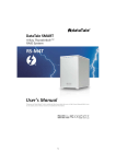
User Manual
- version ENG 1.1 -
1
1. Item Checklist
Thank you for purchasing the LVI SmartGuider autoguiding camera!
Upon receipt, please check that your package is complete and contains the
following items:
1.
2.
3.
4.
5.
6.
Control hand paddle (“Control Paddle”).
SmartGuider camera head
One power supply cable
One 8-pin RJ cable (Control paddle to camera head)
One 6-pin RJ cable (Control paddle to mount’s ST-4 port)
User’s manual
2. Quick Start Guide
Thanks to its ease of use, you can hook up your SmartGuider and be ready
within minutes. Once your imaging rig has been set up, polar aligned and
carefully balanced, here are the main steps to follow:
1.
2.
3.
4.
5.
6.
7.
Make all the necessary connections:
a. Attach the camera to the guide scope, carefully locking the setscrews.
b. Connect the Control Paddle to both the camera head and the mount’s
ST-4 port using the appropriate RJ cables.
c. Connect the Control Paddle to a 12V DC power supply.
Turn the LVI SmartGuider on
Search for a suitable guide star
Focus with the SmartEye parfocal eyepiece (*)
Calibrate the mount (*)
Set the camera’s advanced options (*)
Start autoguiding.
(*) The steps marked with a star, such as focusing and calibration, could not
always be necessary. Please consult Section 4 (“Tips and Tricks”) for details.
2
3. Using the SmartGuider
The SmartGuider’s control paddle features a wide pixel matrix screen, whose
colors (amber on a black background) and brightness do not compromise the
eye’s delicate adaptation to darkness.
In this section we describe the content and functionality of all of the available
user screens: for a quick and effective overview of their usage, please check out
the flowchart available in the download section of LVI’s web site. Most screens
can have up to three different options on their bottom line, which can be activated
by pressing the corresponding button on the control paddle (from left to right).
After connecting the power supply, turn the camera on by pressing and
holding the central button until the LVI logo shows up; shortly thereafter, the
message “YOUR SMARTGUIDER IS READY” informs you that the startup phase
is complete and the camera has come online.
Press OK to go to the first user screen:
In the above screen, you can turn off the camera by pressing and holding the
left button (OFF), while selecting BASIC with the central button will take you to
the basic settings screen (MENU BASIC):
3
With EXIT you can go back to the previous menu, while FOCUS takes you to
the next step (guide star focusing). OPTION enables to adjust the display and
keyboard backlight level and the buzzer volume.
The two basic settings menus are shown below: brightness (left) and buzzer
volume (right):
You can adjust both the brightness and the buzzer volume with the two
triangular keys on the control paddle: four levels are available, from 1 (minimum)
to 4 (maximum). EXIT takes you back to the basic settings screen.
Now let’s have a closer look at the focusing procedure.
Before mounting the camera onto the guide scope’s drawtube, you have first to
center the brightest star in the field of view which is closest to your imaging target
with a wide-field, low-power eyepiece; use then the special SmartEye eyepiece to
focus the guide scope and fine tune the position of the star chosen. This
eyepiece will deliver a perfectly focused and centered star in the camera’s FOV.
When you press on FOCUS, the SmartGuider scans the whole frame to look
for the previously selected guide star:
After a while (the actual duration of the search phase is not always the same),
the SmartGuider will inform you of the outcome with a simple message: “STAR
FOUND!” or “STAR NOT FOUND!”:
4
If the guide star was not found (upper right), the SmartGuider goes
automatically back to the MENU BASIC screen: in this case a brighter star has to
be chosen. If the star has been found (upper left), we can proceed to the
important focusing menu:
In this screen, the X and Y offsets (1 offset unit = 4 sensor pixels) denote the
position of the guide star relative to the detector center, and the small cross in the
rectangular box (see above) indicates the star’s approximate location in a
graphical form. If the star happens to be lying too close to the sensor’s edges
(Bounds: X OFFSET ±82, Y OFFSET ±46), you can try to center it by
CAREFULLY nudging the mount along the four directions with the drive keypad
at guiding speed. If the star is thrown off the active area, it will be lost (STAR
LOST! message pops up) and you will have to start over with focusing.
Two focusing aids are available: the FOCUS STAR index and the circle on the
right-hand side of the screen: they both show the diameter of the star (in pixels)
on the detector in numerical and graphical form respectively. Therefore, the lower
the number, the better the focus: a properly focused star should be 3 to 8 pixels
wide according to the brightness and air turbulence.
Once the guide star has been correctly centered and focused, we can select
CALIBR to get to the calibration screen: press OK to start calibrating the mount.
5
The calibration process can last up to a few minutes. Upon completion, the new
calibration parameters are automatically stored into the camera’s non-volatile
memory (the SAVE icon showed here on the bottom left). In case you want to
reuse the parameters from last calibration, just choose LOAD from the focusing
menu (screen on the lower right). Please see note on calibration on page 9.
At this point we come to the autoguiding screens:
The SmartGuider is standing by (Status: READY, screen on the upper left)
before starting the actual autoguiding phase (Status: GUIDING, screen on the
upper right) by selecting START. The two graphs allow real-time monitoring of
guiding corrections issued to the mount. You can interrupt the autoguiding
process by pressing STOP at any time, while EXIT will take you back to the basic
settings screen.
It might happen the guide star get lost (1 beep per second and STAR LOST):
this can be due to a number of different reasons, e.g. because the sky has
clouded over, the optics have dewed up, or the star has been thrown off the field
6
of view by a wind gust or even because the telescope has been touched. If the
star remains invisible for up to 30 seconds, the camera will still be able to
resume autoguiding; otherwise, the current session is aborted and the execution
flow goes back to the MENU BASIC screen to search for a new guide star.
From the autoguiding screen, pressing the ADVAN menu item brings up the
advanced settings screen:
EXIT will take us back to the previous menu, while by pressing AGGRESS X we
come to the following screens:
With the two triangular arrows (UP and DOWN), you can adjust the
aggressiveness in the X axis (upper left) and in the Y axis (upper right).
The aggressiveness in both axes can range from 1 to 6 (1-2=LOW, 3-4=MILD, 56=HIGH) and expresses the degree of reactivity of corrections: a high value will
urge the camera to immediately correct for the slightest displacement, whereas a
low value will yield a much smoother behavior. See more details at page 10.
4. Tips and Tricks
The SmartGuider is very simple and intuitive to use. However there are some
phases, namely selection of a suitable guide star, focusing and calibration, which
are critical in maximizing the performance of your SmartGuider and therefore
deserve special attention. For further details, please contact LVI.
7
4.1 Error messages
>
STAR LOST! – This message may occur in such cases:
1. Clouds rolling in (during AUTOGUIDING READY and GUIDING).
2. Lenses getting wet (during AUTOGUIDING READY and GUIDING).
3. Too high guiding speed (during MOVING MOTORS…).
Case 1 and 2: the SmartGuider warns the user both with a visual message and
an audible signal, one beep per second until the star becomes visible again, for
up to 30 seconds. Case 3 and 4: adjust the guiding speed to a lower level
through the mount controls or check the Control Paddle to ST-4 mount cable.
> STAR NOT FOUND! – This message may occur when the SmartGuider
camera cannot find a suitable star after STAR SEARCH… command.
> MOTOR NOT MOVING! – This message may occur when the SmartGuider
camera cannot move mount’s motors during calibration. You might want to check
the autoguiding cable or the mount’s autoguiding port pin assignment.
> COMMUNICATION ERROR! – The following message is displayed if the cable
connecting the CPU and the camera head gets accidentally disconnected, or in
case of problems with the electrical connections or the power supply.
4.2 Choosing a suitable guide scope
Thanks to its sub-pixel guiding capability, the SmartGuider does not call for
telescopes with very long focal length or particularly wide aperture. As a rule of
thumb, when imaging with digital SLRs or CCDs (pixel size between 5 and 8
microns), the guide scope should have no less than the half of the focal length as
that of the main instrument. In any case, it is advisable to use refractors instead
of slow catadioptric reflectors (e.g. Maksutovs with f/ratio of 10 and upwards),
since focusing by movable primary mirror can easily lead to exposure trailing
even if the tracking performance looks apparently good. Moreover, there are
cases where high magnification is not always an advantage, due to lower
brightness and increased sensitivity to atmospheric turbulence (seeing).
8
4.3 Guiding Speed adjustment
The SmartGuider automatically adjusts the exposure time according to the
guide star’s brightness: shorter for bright stars, longer for dim ones. This also
affects the frequency of corrections to the mount: bright stars allow for continuous
position control, which also ensures that all sorts of tracking errors, including the
component resulting from periodic error and atmospheric turbulence, will be
easily guided out. Bright stars are best to compensate for the most erratic
periodic errors, or with guide scopes having a shorter focal length than that of the
main optics. In this case, we advise using a moderate guiding speed (0.15 - 0.5X)
with HIGH aggressiveness.
On the other hand, fainter stars imply a less frequent correction of tracking
errors: this makes them not as suitable for mounts with an irregular periodic error.
However, long exposure times required by faint stars could come in handy to
minimize the influence of bad seeing. Here we suggest a very low guiding speed,
best if no higher than 0.25X with MILD aggressiveness.
Medium brightness stars (visual magnitude between 3 and 6) generally yield
best performance.
4.4 Search for a suitable guide star
The telescope must not be touched during calibration, otherwise the relevant
parameters could not be calculated correctly. This also applies to the Control
Paddle unit which must not stay in your hand!
If the search for the guide star fails, you can manually move the guide scope
looking for a brighter star.
If the camera does not manage to find a sufficiently bright star, a micrometric
guide scope support will help. In case an off-axis guider is being used, the pickoff prism and tube can be moved and/or rotated to find a brighter star.
9
4.5 Mount calibration
The telescope must not be touched during calibration, otherwise the relevant
parameters could not be calculated correctly. This also applies to the Control
Paddle unit which must not stay in your hand!
Once calibration is over, the parameters are permanently stored into the
SmartGuider’s internal memory (EEPROM) for later use, provided that the
following precautions are taken into account:
1. Always guide on stars lying in the same side of the sky (with respect to the
local meridian) as that where the calibration was last performed;
2. NEVER take the camera off the guide scope;
3. NEVER rotate the camera in the guide scope focuser.
In all other cases, the camera must always be recalibrated.
It might take a relatively long time for the calibration process to complete,
especially with guide scopes of short focal length (under 500 mm).
It is also advisable not to use too dim a star for calibration, otherwise just a few
thin clouds or a little dew on the lenses could cause the star to be lost and
jeopardize the final result of this important process.
4.6 Autoguiding and aggressiveness
In practice, the aggressiveness parameter defines the “reaction threshold” (in
terms of sensor pixels), i.e. the value of the offset between two consecutive
exposure cycles above which the camera will make a correction.
The lower the aggressiveness, the higher the tracking error allowed and viceversa.
HIGH values are suitable when using small refractors featuring a focal length
1,5-2 times smaller than the main instrument. MILD values are for guide scopes
of about the same focal length and LOW ones are best in case of very long guide
scopes or off axis guiding (typically SCTs).
During autoguiding, the trend of the X and Y graphs should always be staying
as smooth as possible. It is advisable to start off with default values for
10
aggressiveness and guiding speed; then both parameters can be fine tuned to
achieve the best possible sync between your SmartGuider and your telescope.
If you notice any significant oscillations about the zero position of one or both
graphs (overcorrection), the guiding speed should be decreased with the mount
drive keypad until the oscillation becomes less important (ideally, almost
negligible). Anyway, it must be noted that a little oscillation across the zero line is
acceptable since both graphs depict the offset between two consecutive
exposures with a 2X scale. So, two pixels on the tracking graph are actually
equivalent to one single pixel on the detector. If the oscillation continues even
with the guiding speed at its lowest possible value, the aggressiveness has to be
decreased.
In case the profile of one or both graphs keeps steadily above or below the zero
value (undercorrection), the guiding speed has to be slowly increased until the
graph profile goes back to hovering around the zero position. If no improvement
is seen even with the guiding speed at its highest value, the aggressiveness must
be increased.
On nights of bad seeing, and especially with long focal length guide scopes, it
could be worthwhile to slightly defocus the guide star, so that the effect of highfrequency twinkling is mitigated somewhat and the camera won’t try to “guide the
seeing out”.
Should the graphs still be showing a small, jerky oscillation in spite of the above
precautions, please make sure your equipment is properly balanced in both axes.
It must be stressed that a perfect balance of all the weights, the quality and
solidity of all the mechanical supports and adapters is of paramount importance
in getting round stars and well-tracked exposures! Sometimes, trailing due to
differential flexure can ruin your pictures even with apparently smooth tracking.
11
5. Technical Specifications
CAMERA
Sensor............................................................................Mono 1/3" Aptina MT9V032
Sensor resolution.........................................................752x480, 6-µm square pixels
Exposure time range............................................................Auto, 0.001 - 2 seconds
Housing................................................................Aluminium, with polycarbonate lid
Nosepiece........................................Standard 1.25-inch (31.8mm) with filter thread
Connectors...............................................................................................8-pin RJ45
Size and weight...................................................D=65mm, H=50mm, Weight: 110g
CONTROL PADDLE
Case………......................................................................................ABS, black color
Keypad......................................Three membrane keys with amber back-illumination
Display..................................2.5-inch amber graphical LCD, 128x64 pixel resolution
Connectors..................................................8 pin RJ45, 12V DC jack, 6 pin RJ12 pin
Size and weight..................................................LxHxD: 55x96x28mm, Weight: 220g
Power requirements…….........................................................6~14V DC, 90~200mA
FEATURES
- Automatic guide star search
- Real-time monitoring of guide star position and focus
- Automatic axis calibration with permanent storage of parameters
- Adjustable display backlight and buzzer volume.
- Adjustable dual-axis aggressiveness
- High-precision 2X sub-pixel autoguiding
GUIDE STAR BRIGHTNESS
60-mm guide scope…………………........................................................approx. 7.5
80-mm guide scope……………………....................................................approx. 8.0
100-mm guide scope…………………......................................................approx. 8.5
FIELD WIDTH AND IMAGE SCALE
Scope with F = 300mm...........FOV: 51.7x33.0 arcmin............scale: 4.13 arcsec/px
Scope with F = 500mm...........FOV: 31.0x19.8 arcmin............scale: 2.48 arcsec/px
Scope with F = 800mm….......FOV: 19.4x12.4 arcmin….........scale: 1.55 arcsec/px
12