1
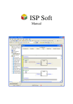
www.infoPLC.net PLC Lab Manual Prepared By Eng. Wael Younis 2008-2009 Include CD-ROM www.infoPLC.net PLC Lab Manual 2 Table Of Contents Experiment #1 Operating a simple loads using relays, switches and pushbuttons 3 Experiment #2 PLC Input – Output Wiring Methods 6 Experiment #3 Programming the PLC Via Ladder logic 14 Experiment #4 Position control for satellite dish DC motors 26 Experiment #5 Starting Three Phase induction Motors Via Star-Delta Starter 30 Experiment #6 Programming PLC Via SFC 36 www.infoPLC.net PLC Lab Manual 3 Experiment #1 Operating a simple loads using relays, switches and pushbuttons OBJECTIVES After successfully completing this laboratory, you should be able to: Identify the basic components of the control board. Assemble and arrange a simple control board. Explain the operation of electromagnetically controlled circuits. Operate a simple loads using relays, switches and pushbuttons. 1. Equipments 3x10A mcb. 230V(coil), 50Hz, 10A Relay Green and red indicator lamp. NO and NC pushbuttons. ON-OFF switch. Toggle switch (1-0-2). Flexible wires. Single phase power source. (42x55)cm wooden board. Mounting rails. Wiring ducts (panel type) Terminals. 2. Procedure Part 1 1. Using the wooden board, wiring ducts and mounting rails, assemble and arrange the control board as shown in figure 1.1. 32,4 3 3 14 55 3 14 3 3 16,2 1,8 42 Fig. 1.1 The power circuit diagram for a direct on line starter www.infoPLC.net PLC Lab Manual 4 Part 2 1. Assemble the components of the circuit shown in figure 1.2 on the control board and make the required wiring and connections. mcb 1x10A L(220VAC) SW1 220V/50Hz COIL R R L2 L1 R N Fig. 1.2 Energizing and de-energizing relay using on-off switch 2. Once you are finished with the connections, call the instructor to check it for you and make sure that it is correct. 3. Connect the circuit to the power source and try to change the position of the switch SW1. What is your observation ? Part 3 1. Assemble the components of the circuit shown in figure 1.3 the control board and make the required wiring and connections. mcb 1x10A L(220VAC) ON R L2 L1 R OFF 220V/50Hz COIL R R N Fig. 1.3 Energizing and de-energizing relay using on-pushbutton and off-pushbutton 2. Once you are finished with the connections, call the instructor to check it for you and make sure that it is correct. www.infoPLC.net PLC Lab Manual 5 3. Connect the circuit to the power source and try to operate the motor by pressing ON-push button is pressed and also stop the motor by pressing the OFF-push button. What is your observation ? Part 4 1. Assemble the components of the circuit shown in figure 1.4 the control board and make the required wiring and connections. mcb 1x10A L(220VAC) SW1 2 1 R2 R1 L2 L1 0 R1 220V/50Hz COIL R2 N Fig. 1.4 Energizing and de-energizing relays using toggle switch (1-0-2) 2. Once you are finished with the connections, call the instructor to check it for you and make sure that it is correct. 3. Connect the circuit to the power source and try to change the positions of the switch SW1 (1-0-2). What is your observation ? www.infoPLC.net PLC Lab Manual 6 Experiment #2 PLC Input – Output Wiring Methods OBJECTIVES After successfully completing this laboratory, you should be able to: Read and explain the nameplate of DELTA’s PLC DVP Series Model . Make different types of PLC input wiring. Make different types of PLC output wiring. 1. Basic Information 1.1. DELTA’s PLC DVP Series Model Explanation DELTA’s PLC DVP Series has main processing units and extension units. The main processing units offer 14-60 points and the extension units offer 8-32 points. The maximum input/output can be extended up to 128 points. It also can be used on applications according to INPUT/OUTPUT points, power sources, output modules, digital/analog exchanges (A/D & D/A converter). In addition, DVP SS Series has the special modules (AD/DA/PT/TC/XA) used for extending its functions and the maximum special modules can be extended up to 8 units. Nameplate Explanation Fig. 1.2 Delta programmable logic controller name plate Serial Number Explanation www.infoPLC.net PLC Lab Manual 7 Model Explanation Fig. 2.2 Delta programmable logic controller name plate model explanation. 1.2. Features of the DVP PLC Fig. 2.3 Features of the DVP PLC 1 2 3 4 5 6 7 8 DIN rail clip DIN rail (35mm) Direct mounting holes cover Programming port cover (RS-232) Extension port I/O terminals I/O terminals Input indicators 9 10 11 12 13 14 15 Output indicators Status indicators, POWER, RUN ERROR I/O terminal cover I/O terminal cover I/O terminal nameplate panel I/O terminal nameplate panel RS-485 Communication port www.infoPLC.net PLC Lab Manual 1.3. 8 Wiring Guidelines Fig. 2.4 DVP-14ES PLC terminal layout 1.3.1 Power Input Wiring Figures 2.5 and 2.6 show various possible external power connections for DVP PLC. When wiring AC power, the ‘Live’ cable should be connected to the ‘L’ terminal and the ‘Neutral’ cable should be connected to the ‘N’ terminal. When wiring DC power, the ‘positive’ cable should be connected to the ‘+’ terminal and the negative should be connected to the ‘-‘ terminal. At no time should the power supply terminals be connected to any other terminal on the PLC. AC Input Type Fig. 2.5 AC input type PLC wiring The +24V supply output is rated at 0.4 Amperes. DO NOT connect external power supply to this terminal. FUSE Protection: there are internal fuses on all DVP PLCs. However, the fuse does not guarantee the prevention of DVP PLC damage, but it will provide added protection. DC Input Type Fig. 2.6 DC input type PLC wiring www.infoPLC.net PLC Lab Manual 9 1.3.2 Input Point Wiring All versions of the DVP PLC have Input / Output circuits that can connect to a wide variety of field devices. DC Input PLCs have two modes of operation: SINK and SOURCE. Sink = Current flows into the common terminal S/S Source = Current flows out of common terminal S/S For example, we simply connect the common terminal S/S to the supply source(+). By adding the switch, between the supply(-) and the input, we have completed the circuit. Below are two circuit diagrams showing both the sinking and sourcing inputs. Fig. 2.7 Sinking and sourcing inputs 1.3.3 Output Point Wiring There are three kinds of DVP-Series PLC outputs: Relay, SSR and Transistor. All relays used in DVP series PLC have passed the standard of IEC 947-5-1 under AC-15 (the rated current and voltage) specification for a cycle test of 6050 times. www.infoPLC.net PLC Lab Manual 10 Fig. 2.8 Rely output type PLC wiring Fig. 2.9 Transistor output type PLC wiring Be careful with the connection of the common terminals when wiring output terminals. For example, when wiring DVP14ES00R, note that there are six normally-open SPST relays available. They are organized into 4 groups with individual commons. The figure below shows the relays and the internal wiring of the PLC. Note that each group is isolated from the other groups: C0 Y0 C1 Y1 C2 Y2 C3 Y3 Y4 Y5 Fig. 2.10 relays groups and the internal wiring of the PLC. www.infoPLC.net PLC Lab Manual 11 Relay Output Wiring Methods Fig. 2.11 Relay Output Wiring Methods 1. 2. 3. 4. 5. 6. 7. 8. 9. 10. 11. Surge absorbing diode: increases relay contact life. Emergency stop: use an external switch. Fuse: 5 to 10A for every 4 output points to protect the PLC’s. output circuit. Surge absorber: reduces noise on AC inductive loads. Unused terminal: do not connect. DC supply. Neon lamp. AC supply. Incandescent lamp. Mutually exclusive outputs: Use external hardware interlocks, as well as those in the PLC program, for maximum safety. Transistor Output Wiring Methods Fig. 2.12 Transistor Output Wiring Methods www.infoPLC.net PLC Lab Manual 12 1. 2. 3. 4. DC supply. Emergency stop. Fuse. If Y0 is used as a pulse train output with PLSY, use a pull up resistor to ensure the output current is greater than 0.01A for correct operation. 5. If Y1 is used with PWM, use a pull up resistor to ensure the output current is greater than 0.01A for correct operation. 6. Mutually exclusive outputs: use external hardware interlocks, as well as those in the PLC program, for maximum safety. 7. Unused terminal: do not connect. 2. Equipments DVP14ES00R 1x10A mcb. 230V(coil), 50Hz, 10A Relay Green and red indicator lamp. NO and NC pushbuttons. ON-OFF switch. Flexible wires. Single phase power source. Control board. 3. Procedure 1. Assemble the components of the control circuit on the control board and make the required wiring and connections as shown in figure 2.13. SW3 SW2 SW1 mcb 1x10A PB2 PB1 Pulser N 220V/50Hz L S/S L X4 X5 X6 X7 X0 X1 X2 X3 N DVP-14ES +24V Y0 24G Y1 Y2 Y3 Y4 C0 C1 C2 C3 Y5 +24VDC L1 R1 220V/50Hz COIL L2 R2 220V/50Hz COIL 220V/50Hz 24GND Fig. 2.13 The power circuit diagram for a direct on line starter 220V/50Hz www.infoPLC.net PLC Lab Manual 13 2. Make the required wiring and connections for the power circuit as shown in figure 2.14. +24V R2 R1 Left D1 D2 LSL LSR M R2 R1 GND 3. Once you are finished with the connections, call the instructor to check it for you and make sure that it is correct. www.infoPLC.net PLC Lab Manual 14 Experiment #3 Programming the PLC Via Ladder logic OBJECTIVES After successfully completing this laboratory, you should be able to: to convert a simple electrical ladder diagram to a PLC program. Know the difference between physical components and program components. sketch the ladder programs using the tools available in WPLSoft. Download the program to the PLC. operate the program, via placing the PLC in the RUN mode . 1. Basic Information 1.1. Introduction PLCs are special computers designed to operate in the industrial environment with wide ranges of ambient temperature and humidity. They have a number of different programming languages which include Ladder logic, Mnemonic instructions, and Sequential Function Charts. Ladder logic is the main programming method used for PLCs. It is a graphical language which has been developed to mimic relay logic. The decision to use the relay logic diagrams was a strategic one. By selecting ladder logic as the main programming method, the amount of retraining needed for engineers and tradespeople was greatly reduced. a software tool called Wpl runs on a personal computer allows users to sketch the ladder diagram and then transfers its compiled code serially to the PLC. Such a software tool is more convenient and it supports mnemonic and SFC programming languages as well. 1.2. WPLSoft Installation and setup Start-up your computer to Windows 95/98/2000/NT/ME/XP system. Insert WPLSoft CD into the CD-ROM disk or download installation program from http://www.delta.com.tw/product/em/plc/plc_main.asp (If the installation program is downloaded from the website, it needs to be saved in the designated directory after uncompressing, and then the installation can be started.) Click “START”, and then click on “RUN” Designate the location where WPLSoft is to be installed www.infoPLC.net PLC Lab Manual 15 The program show the dialog box explaining the WPLSoft copyright. Please click "Next" to proceed with the installation. Enter the user name and the organization then click “Next>” . Click "Next" to comtinue or click "Change“ to install to a different folder. www.infoPLC.net PLC Lab Manual Click “Install” to continue. Click “Finish” to complete the installation. 16 www.infoPLC.net PLC Lab Manual 17 DELTA’s PLC DVP Series has main processing units and extension units. The main processing units offer 14-60 points and the extension units offer 8-32 points. The maximum input/output can be extended up to 128 points. It also can be used on applications according to INPUT/OUTPUT points, power sources, output modules, digital/analog exchanges (A/D & D/A converter). In addition, DVP SS Series has the special modules (AD/DA/PT/TC/XA) used for extending its functions and the maximum special modules can be extended up to 8 units. 1.3. Delta PLC memory map In the previous section we introduced two types of memory variables in Delta PLCs; the input relays and the output relays. In Delta PLCs there are total of 8 memory location types as described below. Input Relays: Single bit variables and can be extended to 128 points. They are indicated with X sequence in Octal numbering mode. Output Relays: Single bit variables and can be extended to 128 points. They are indicated with Y sequence in Octal numbering mode. Internal Auxiliary Relays: Single bit variables. They are indicated with M sequence in Decimal numbering mode ranging from M0 to M1279. M1000 and above are used for system flags and special purpose auxiliary relays. Steps: Single bit variables indicated by S sequence in Decimal numbering mode ranging from S0 to S127. Timers: Indicated by T sequence in Decimal numbering mode ranging from T0 to T127. Each timer has a 16-bit holding register for its preset value as well as a single bit variable representing its contact. Counters: Indicated by C sequence in Decimal numbering system. Similar to Timers, each counter has a holding register and a single bit contact. There are 128 16-bit counters ranging from C0 to C127 and there are 13 32-bit counters indicated as C235 to C238, C241, C242, C244, C246, C247, C249, C251, C252, and C254. These later counters are referred as high speed counters. Data Registers: 16-bit variables indicated by D sequence in Decimal numbering www.infoPLC.net PLC Lab Manual 18 mode ranging from D0 to D599 and from D1000 to D1143. D1000 and above are special purpose registers. Index Registers: Two pointers indicated by E and F. They are D1028 and D1029 respectively. These memory locations are reached easily using their names. However one may reach them by means of the PLC device addresses specified by Delta. This method is useful when these memory locations are monitored or preset at run time by an external devise such as a personal computer. The device addresses table of Delta PLCs is illustrated in Table 2.1. It is not a traditional memory map where each location is byte width. However, the location size depends on the variable type. Table 2.1: Device address table of Delta PLCs. 1.4. Ladder logic and mnemonic programming The instructions from a ladder diagram, mnemonic, or SFC are translated to machine code that can be stored in the PLC memory. Each horizontal rung on the ladder in a ladder program represents a line in the program and the entire ladder gives complete program in “ladder language”. There are three basic symbols used in ladder logic. The first one is NO - NC contacts : NO contact is an instruction that tells the processor to look at a specific bit in its RAM memory. If the bit is 1, the instruction is true. and if it is 0, the instruction is false. The determining factor in choosing which bits in its memory to look at is the address. It could be some auxiliary bit (M), a timer contact (T), a counter contact (C), a state bit (S), or it might be connected to an external input (X). X0 Normally Open Contact NC contact plays the same role as the previous one, except that if the bit addressed is 1, the instruction is false and if it is 0, the instruction is true. X0 Normally Closed Contact The second symbol is output: for outputting to the output module. If the instructions to the left on its rung have a true path to the leftmost vertical rail, then the PLC will set the bit to which it is referenced via the address to 1. If no complete true path is available, it will set the bit to 0. Y0 Device Output www.infoPLC.net PLC Lab Manual 19 The third symbol is special instruction boxes: Along with the basic logic instructions addressed in the previous part, PLCs are microprocessor-based and they facilitate a wide area of useful built in functions like timers, counters, comparators . CNT C0 K10 Counter Example Let us assume that we have two inputs buttons and three output devices connected to a PLC terminals X1, X2, Y1, Y2, and Y3 respectively. Assume also that the PLC is loaded with the program shown in Figure 2.5. The program has 3 rungs which are explained as follows: Rung 1: If we push on button X1, its associated internal bit labeled X1 is logic 1 (true). Thus, when the processor executes this rung via the input instruction -] [-, it sees the rung’s input condition as true. Therefore it puts a 1 in the output bit Y1. This ladder program line is converted to mnemonic instruction as LD X1 OUT Y1 Rung 2: The processor works through the inputs from left to right, and the output instruction sees a true condition only when it sees a true path via input instructions to the left rail. If you push both push buttons connected to terminals X1 and X2, then the processor sees their associated bits logic 1 and hence puts a 1 in the output bit Y2. If none or one push button is pushed, the input conditions to the left of the output instruction do not produce a true path. This type of program rung is called an AND because both push buttons, X1 AND X2, must be pushed to activate the output. This rung is converted to mnemonic instruction as LD X1 AND X2 OUT Y2 Rung 3: This type of instruction is an OR gate because there are two pathes that will turn the output: either push button X1 OR X2 is pushed. It is implemented in mnemonics as LD X1 OR X2 OUT Y3 1.5. Functions on PLCs Counters www.infoPLC.net PLC Lab Manual 20 When the operation result of instructions preceding the CNT instruction has changed from OFF to ON, 1 is added to the count value. When the counter has counted out (count value = set value), the state of the counter contacts are toggled. In the following example the output Y0 is activated after entering 5 clock pulses at input When the operation result of the instructions preceding the CNT instruction remain on, counting is not performed. After the counter has counted out, the count value and the status of the contact will not change until the RST instruction is executed. A negative number cannot be used as a set value. When the set value is 0, the same processing as for 1 is performed. The instruction CNT uses 16-bit registers to accumulate counted values in the valid counters domain (C0 to C127). On the other hand, the instruction DCNT uses 32-bit registers for high speed counters. Timers When the operation result of instructions preceding the TMR instruction are on, the coil of timer turns on and counts up to the set value. When the timer times out (counted value >= set value), the timer contacts are toggled. In the following example the output Y0 is activated 3 seconds after activating the input X0. Delta PLCs support 128 timers (T0 to T127). The timer will be reset when the operation result of instructions preceding the TMR instruction change from ON to OFF. Moreover, The RST instruction may be used to reset the timer values. Timers use 16-bit registers and a negative number (-32768 to -1) cannot be set as a set value. Other useful functions In the User manual you will find plenty of functions that facilitate data movement, arithmetic, comparison, and other operations similar to instructions provided for traditional microprocessors. For example, the instruction MOV K14 D0 moves the decimal value 14 to data register D0. Another example, the instruction CMP D7 K23 M0 compares the value of D7 with the decimal number 23. If larger M0 will be set, else if equal M1 will be set, otherwise if smaller then M2 will be set. www.infoPLC.net PLC Lab Manual 21 2. Equipments DVP14ES00R 1x10A mcb. 230V(coil), 50Hz, 10A Relay Green and red indicator lamp. NO and NC pushbuttons. ON-OFF switch. Flexible wires. Single phase power source. Control board. 3. Procedure 20V/50Hz SW3 SW2 SW1 mcb 1x10A PB2 PB1 Part 1 : DC motor set-reset circuit 1. Assemble the components of the control circuit on the control board and make the required wiring and connections as shown in the following figure N L S/S L X4 X5 X6 X7 X0 X1 X2 N X3 DVP-14ES +24V Y0 24G Y1 Y2 Y3 Y4 C0 C1 C2 C3 Y5 +24VDC R1 220V/50Hz COIL R2 220V/50Hz COIL 220V/50Hz 220V/50Hz GREEN RED 24GND 2. Make the required wiring and connections for the power circuit as shown in the +24V R2 R1 Left D1 D2 LSL LSR M R2 following figure 3. R1 GND Starting a new project in Wpl, you will be prompt to specify the memory capacity of the target PLC model and a title for the project as shown below. www.infoPLC.net PLC Lab Manual 22 4. Specify 4000 steps for the DVP14ES00R PLC model and write down a suitable project title then click OK. In the Ladder diagram window sketch the program shown below using the tools available in the common tools bar. X4 X5 M0 Internal Relay Y0 R1 Relay Y5 Green Lamp Y3 Red Lamp M0 M0 M0 END 5. Wpl assumes by default that the target PLC is connected to the PC through COM1. You may change this default sitting from Option / Comm. port. To download your program, click on Communication > PLC . Select Write PLC from the drop menu and click OK. 6. To operate the program, the PLC is placed in the RUN mode from Communication / PLC Run. Part 2 : DC motor reversing circuit 1. Starting a new project in Wpl. In the Ladder diagram window sketch a program represents the following control circuit . www.infoPLC.net PLC Lab Manual 23 2. Download your program, click on Communication > PLC . Select Write PLC from the drop menu and click OK. 3. Operate the program, the PLC is placed in the RUN mode from Communication / PLC Run. Part 3 : Sliding Gate system 1. Starting a new project in Wpl. In the Ladder diagram window sketch a program represents the following control system for a sliding gate The program should satisfy the following conditions : The motor should be overload protected. The gate should stop in case of pressing stop-pushbutton. In case of pressing Up-pushbutton the gate should move up to max limit(limit switch 2) . www.infoPLC.net PLC Lab Manual 24 In case of pressing Down-pushbutton the gate should move down to max limit(limit switch 1) . In case any one passed the photocell interrupts the down state and activates the up state. The flusher lamp to be operated in the down state. Required mechanical and electrical interlocks to be used. 2. Download and operate your program . Part 4 : Water Pump system 1. Starting a new project in Wpl. In the Ladder diagram window sketch a program represents the following control system for a water pump The system consists of one water pump and controlled via two float switches. The system should satisfy the following conditions : The pump should run if and only if the well is full and the tank is empty. The pumps should be protected against : o Phase failure. o Changing the phase sequence. o Under voltage. The pump should run after a time delay of 5 seconds. The system should be controlled by two float switches (see figure 1). www.infoPLC.net PLC Lab Manual 2. Download and operate your program 25 www.infoPLC.net PLC Lab Manual 26 Experiment #4 Position control for satellite dish DC motors OBJECTIVES After successfully completing this laboratory, you should be able to: to convert a simple electrical ladder diagram to a PLC program. Know the difference between physical components and program components. sketch the ladder programs using the tools available in WPLSoft. Download the program to the PLC. operate the program, via placing the PLC in the RUN mode . 1. Basic Information In the satellite dish motor position control system there are two set points and two sensors (limit switches) used to feedback the position information to the controller. In the general case, the system may have almost continuous set points. Thus a special sensor is required to report the position information back to the controller. One cheep method is to fix a small permanent magnet to one side of the motor shaft and use a magnetic sensor to count the number of revolutions of the rotor as illustrated in Figure 4.1. Figure 4.1: Magnetic sensors used in satellite dish motors. The position information precision provided by these magnetic sensors is not adequate in more professional position control applications. Optical encoders, on the other hand, are more common in these applications and capable of generating hundreds or thousands of pulses per rotor revolution. Figure 4.2 depicts a 1000 pulse resolution optical encoder and its internal structure. Position control using DC motors is based on feedback as illustrated in Figure 4.3. In the literature there are many tools developed to design continuous or digital controller that meets some design parameters such as overshoot, rise time, settling time, and steady state error. However we prefer here to simplify the problem by assuming that the mechanical and time constants of the system are zeros. That is the motor system responds instantaneously to its input voltage. This is justifiable when the motor is coupled by high ratio step down gear box. In this case we do not have to design a linear voltage driver for the motor and we may use the circuit shown in Figure 4.4 to drive the motor. The control circuit should instruct the relays to feed the motor with the DC forward polarity when the error signal is positive or reverse polarity when the error signal is negative. www.infoPLC.net PLC Lab Manual 27 Figure 4.2: Optical encoder. Figure 4.3: Feed-back position control. Once the error signal equals zero relays disconnect the power supply of the motor. It is difficult and impractical to realize this controller using traditional relay control circuits. Figure 4.4: Power circuit of the system. Conversely speaking when implemented using a PLC. Figure 4.5 illustrates the hardware connection of the control circuit. www.infoPLC.net PLC Lab Manual 28 Figure 4.5: PLC-based position control. 2. Equipments DVP14ES00R 1x10A mcb. 230V(coil), 50Hz, 10A Relay Green and red indicator lamp. NO and NC pushbuttons. ON-OFF switch. Flexible wires. Satellite dish motor Single phase power source. Control board. 3. Procedure Part 1 : Position control using internal set point: 20V/50Hz SW3 SW2 SW1 mcb 1x10A PB2 PB1 1. Assemble the components of the control circuit on the control board and make the required wiring and connections as shown in the following figure N L S/S L X4 X5 X6 X7 X0 X1 X2 X3 N DVP-14ES +24V Y0 24G Y1 Y2 Y3 Y4 C0 C1 C2 C3 Y5 +24VDC R1 220V/50Hz COIL R2 220V/50Hz COIL 220V/50Hz 220V/50Hz GREEN RED 24GND www.infoPLC.net PLC Lab Manual 29 2. Make the required wiring and connections for the power circuit as shown in the following figure +24V R2 R1 Left D1 D2 LSL LSR M R2 R1 GND 3. Assuming that the set point is available in data register D1, start a new project in Wpl and in the Ladder diagram window sketch a program represents the position control problem of the satellite dish motor illustrated in the previous section. 4. Download and operate your program . Part 2 : Position control using External set point: 1. Using tow pushbuttons PB1 and PB2 to increase and decrease the set point develop a ladder diagram represents this position control problem. 2. Download and operate your program . www.infoPLC.net PLC Lab Manual 30 Experiment #5 Starting Three Phase induction Motors Via Star-Delta Starter OBJECTIVES After successfully completing this laboratory, you should be able to: Start the three phase induction motor via star-delta connection using PLC Start and reverse the direction of the three phase induction motor via star-delta connection using PLC 1. Basic Information 1.1 Semi-automatic Star-Delta Starter Semi-automatic and fully automatic starters require three contactors to connect the motor windings first in star and then in delta. The power circuit diagram showing the scheme is given in Fig. 5.1. Fig. 5.1 Power circuit diagram for a star-delta starter Whenever one has to make connections for a star-delta starter it is advantageous to draw the winding diagram as shown in the right hand side of Fig. 5.1. It helps to remember that for delta connection, finishing end of one winding is to be connected to starting end of the other winding as shown in the figure. The three phase supply is then given at the three junctions. Now let us refer to the power circuit diagam of the starter as given in Fig. 5.1. The sequence of operation of the contactors is as follows. First the contactor S will close for star connections, then the main contactor M will close and lastly contactor S will open and contactor D will close for delta connection. When star contactor is first closed, winding terminals A2, B2, C2 get connected together through the contacts of contactor S and thus the windings get connected in star. Now when the main contactor is closed supply reaches terminals A1, B1, C1 and therefore the motor windings are energised in star-connection. For delta connection, first the star contactor should open before the delta contactor is closed. If delta contactor gets closed while star contactor is still ON, dead short circuit takes place at the outgoing leads of over-load relay through contactor D and S. This is taken care of by providing interlocking of auxiliary contacts between contactors S and D. When star contactor www.infoPLC.net PLC Lab Manual 31 opens and delta contactor closes motor winding terminals A2, B2, C2 get connected to B1, C1, A1 through the closed contacts of contactor M and the motor runs in delta connection. In a semi-automatic starter, the motor runs in star connection as long as ON-push button is kept pressed. When ON-push button is released the motor gets connected in delta and continues to run till the OFF-push button is actuated or over-load relay trips. The control diagram for a semiautomatic starter is shown in Fig. 5.2. Explanation of control operation is as follows: When ON-push button is pressed contactor S gets energized and it connects the motor windings in star connection. (Refer power diagram in Fig. 5.1). Simultaneously the auxiliary contact S1 closes and S2 opens. Closing of S1 causes energisation of contactor M which is then kept energized through its own auxiliary contact M1. Opening of contact S2 provides interlocking i.e., the delta contactor cannot get energized as long as contactor S is energized. Contactor S remains energized as long as the ON-push button is kept pressed because there is S. Fig. 5.2 Control circuit for a semi-automatic star-delta starter When the ON-push button is released, contactor S gets de-energised, its auxiliary contacts come back to their original positions as shown in Fig. 5.2. Opening of S1 does not make any difference in operation as the main contactor is now held through its own contact. However, closing of contact S2 causes energisation of the delta contactor. Thus, now the main contactor and the delta contactor are energised simultaneously and the motor runs with its windings connected in delta. Whenever the motor is to be stopped the OFF-push button is pressed, both the contactors M and D are de-energised (as holding through auxiliary contact of M is broken). Similar action takes place when the control contact of the overload relay opens. 1.2 Semi-automatic Star-Delta Starter In a three phase induction motor, the rotor tends to rotate in the same direction as the revolving magnetic field produced by the stator windings. The direction of the revolving field depends upon the phase sequence of the supply voltage. If the phase sequence of supply to the motor windings is changed by interchanging two phase leads, the direction of the revolving fields is reversed. Thus the direction of rotation of a three phase induction motor can be reversed if the two supply phase leads to the motor terminals are interchanged. This phase reversal to the motor terminals is accomplished by two contactors. www.infoPLC.net PLC Lab Manual 32 The power diagram for reversing the direction of rotation of the motor and the associated control circuits are shown in Fig. 5.3. Fig. 5.3 Reversing direction of rotation of a three phase induction motor ( a) Power diagram ( b) and ( c) Control circuit diagrams It may be seen from 5.3 (a) that phase reversal to motor terminals has been done by interchanging phase L2 and phase L3 leads at the upper terminals of the reverse contactor R. The forward and reverse contactor are mechanically interlocked i.e., if one of them is closed the other cannot close. This is done to avoid dead short circuit in case both the contactors closing simultaneously. Electrical interlocking has also been provided, by using control contacts. Electrical interlocking is essential even if mechanical interlocking of contactors is provided. This is because, if the coil of contactor which is mechanically interlocked not to close, is energized, its coil gets burnt. The coil gets burnt as it draws large current due to less reactance in this case. Reactance of coil is less as reluctance to flux path increases due to large air gap between the electromagnet and the locked armature of contactor. Forward reverse starters may be designed for either Forward-Reverse Operation or ForwardOff-Reverse Operation. The control diagram in Fig. 5.3 (b) is a simple circuit for ForwardOff-Reverse operation. The motor can be run in forward or reverse direction by pressing FOR or REV push buttons. When say the FOR-push button is pressed contactor F gets energized and is held energized through its auxiliary contact F1. As the interlocking contact F2 is now open the reverse contactor R can not be energized even if the REV-push button is pressed. When the motor is to be reversed, the motor is to be stopped first by pressing the STOP-push button which de-energises contactor F, only then the motor can be run in reverse direction by pressing the REV-push button. Control circuit in Fig. 5.3 (c) is for direct reversing of the motor. In this circuit, for reversing there is no need to first press the STOP-push button. Direction of rotation of the motor can be changed by pressing the respective push button. This is accomplished by using interlocking through NC contacts of the push button in the coil www.infoPLC.net PLC Lab Manual 33 circuits of the contactors. Assume that motor is running in forward direction when contactor F is energized through closed contact F1, NC contact of reverse push button, and normally closed contact R2 of reverse contactor R. When it is desired to reverse the motor direction, REV-push button is pressed, its NO contact closes whereas its NC contact which is in series with coil of contactor F opens. Contactor coil of F is thus de-energized and its holding circuit is also released. De-energization of F also leads to closing of its auxiliary contacts F2. The reverse contactor R is thus energized through NO contact of REV-push button, NC of FORpush button, and NC contact F2 of contactor F. The contactor R remains energized through its auxiliary contact R1. Similar action takes place when the motor is to again run in forward direction by pressing FOR-push button. Induction motors can be safely reversed by direct reversing method as the inrush current is not significantly more than when it is started direct from rest. Direct reversing is also used for bringing a motor to standstill quickly using reverse torque acting as a brake. 2. Equipments DVP14ES00R 1x10A mcb. 230V(coil), 50Hz, 10A Relay Green and red indicator lamp. NO and NC pushbuttons. ON-OFF switch. Flexible wires. Single phase power source. Control board. 3. Procedure Part 1 : Semi-automatic Star-Delta Starter 1. For the following semi automatic star-delta control system sketch the ladder diagram . The input – output diagram of the PLC is shown in the figure. W1 W2 U1 L1 L2 L3 W2 W2 V2 W1 mcb3x10A U2 V2 V1 V1 Main Contactor 220V/50Hz COIL A1 1 3 Delta Contactor 220V/50Hz COIL 5 M 2 A2 4 6 A1 A1 1 3 5 D A2 Overload U1 W2 V1 U2 W1 V2 2 4 6 Star Contactor 220V/50Hz COIL 1 3 5 2 4 6 S A2 U1 U2 www.infoPLC.net PLC Lab Manual 34 N T S R Stop 15 NVR NVR 18 95 95 96 96 13 Star M 14 13 Delta D 14 21 21 D 22 220V/50Hz COIL M A2 220V/50Hz COIL A1 A1 S D A2 A2 Delta Contactor L1 Star Contactor L2 S 22 A1 220V/50Hz COIL X1 X2 X3 Star Delta Stop X4 X4 OL NVR Main Contactor Run Fault N C(Main) PLC 2. Download and operate your program C(Delta) C(Star) Green Lamp Red Lamp Y1 Y2 Y3 Y4 Y5 www.infoPLC.net PLC Lab Manual 35 Part 2 : Semi-automatic Star-Delta Starter with reversing the direction 1. For the following star-delta control system sketch the ladder diagram .The input – output diagram of the PLC is shown in the figure W1 W2 U1 L1 L2 L3 W2 W2 V2 W1 mcb3x10A U2 V2 V1 V1 A1 Main Contactor 220V/50Hz COIL 1 3 Delta Contactor 220V/50Hz COIL 5 F 2 4 A2 6 A1 A2 Delta Contactor 220V/50Hz COIL 1 3 5 2 4 6 1 3 5 R A1 A1 D A2 2 4 6 Star Contactor 220V/50Hz COIL A2 Overload U1 W2 V1 U2 W1 V2 N T S R Stop 15 NVR NVR 18 95 95 96 96 13 Star(F) F 13 Star(R) 13 R 14 13 F 14 14 R 14 13 Delta D 14 21 21 D L2 A1 L1 220V/50Hz COIL S 22 22 A1 A1 A1 R F A2 220V/50Hz COIL A2 S D A2 A2 X1 X2 Star(F) Star(R) X3 Delta X4 Stop OL NVR X5 X6 F(Main) R(Main) PLC D(Delta) S(Star) Green Lamp Red Lamp 2. Download and operate your program Delta Contactor Star Contactor Main Contactor Main Contactor Run Fault N Y1 Y2 Y3 Y4 Y5 Y6 220V/50Hz COIL 1 3 5 2 4 6 S U1 U2 www.infoPLC.net PLC Lab Manual 36 Experiment #6 Programming PLC Via SFC OBJECTIVES After successfully completing this laboratory, you should be able to: Build self starting system for generators using PLC Using SFC to program the PLC. 1. Basic Information 1.1 Sequential Function Chart (SFC) An SFC is bipartite directed graph that contains steps (represented by rectangles), transitions (represented by bars), and directed arcs connecting steps to transitions and transitions to steps. The dynamics of a system described by an SFC is represented by the movement of markers. A marker, represented as a small dot, is placed in a step to indicate that the step is active. The current location and distribution of markers in an SFC is called its marking. The marking of an SFC defines the state of the system. The initial state of a system modeled by an SFC is represented by a step with double border. Outputs of an SFC are combined to steps. A Boolean variable combined to step i equals 1 when step i is active. Transitions represent potential evolutions of the SFC. A transition is enabled if each step preceding it is active. An enabled transition is fired if its receptivity is true. The receptivity of a transition is a level action logic condition. Figure 4.1 illustrates the SFC of an RS flip-flop which is assumed to be initially in the reset state. 1.2 SFC Example Our introductory simple example is the derivation of the SFC which models the behavior of the educational covering machine shown in Figure 6.1. The moving parts of the machine are driven by linear pistons. Pistons may provide linear or angular motion through compressed oil or air whose flow may be controlled electrically by means of electric valves. Figure 6.1: An educational covering machine. There is a horizontally sliding plate driven by piston (Y3) which has two proximity switches (X5 and X4) to indicate the end of the forward and backward piston strokes www.infoPLC.net PLC Lab Manual 37 respectively. Initially the plate is driven forward by triggering a push button (X0). Getting a signal from (X5), the plastic container headed by a foil cover is manually placed in a dedicated hole made in this horizontally moving plate. Since this feeding process is manually done, the significance of the forward proximity sensor (X5) may be ignored. The operator gets the information of the plate position visually without the need for (X5). However, if this part is automated, then (X5) is essential sensor. The covering process is initiated by pressing the push button (X0) again, the piston (Y3) moves the plate backward so that the container is centered under an aluminium plate which is kept at a temperature by means of a heater and a thermostat. The proximity sensor (X4) helps indicating the completion of the backward stroke and thus the container is exactly under the ironing plate. Triggered by this sensor, a vertically mounted piston (Y4) presses the ironing plate over the covering foil and the container. Due to heat the edges of the container starts to melt causing the foil to stick with the container circumference. This process spends 3 seconds after which the vertical piston should be released and then the horizontal plate should be driven forward to start a new cycle. This is accomplished by utilizing two proximity sensors (X2 and X3) to signal the end of the vertical piston down and up strokes respectively. The evolution of the SFC is as illustrated in Figure 6.2 while the machine signals are summarized in Table 6.1. Note that in the transition from S10 to S11, we utilized the signal from the sensor X5. _ ... _&² Figure 6.2: SFC of the educational covering machine. www.infoPLC.net PLC Lab Manual 38 Table 6.1: Signals of the educational covering machine. If you want to ignore the sensor as we mentioned above, you have to replace the transition condition to rising edge of X0 and not the high level of X0. This is due to the fact that arrival to S10 is conditioned by the level of X0 and it is likely that this state will be a transient state if the departure is also conditioned by the high level value of X0. However, what is expected from the system is that the user will press the input push-button, and have a time to raise his hand before pressing it again. Moreover, it is a good idea to include in these transitions the signal from X3 as well in order to protect the pistons in case of failure of the vertical motion. In other words, you will not allow the motion of the horizontal direction unless the vertical piston is in its UP position. 1.3 Generator Self Starting System Figure 6.1 shows control circuit diagram for generator self starting, in this circuit if the remote contact is closed first the fuel pump is run via relay (R1), after some time delay the self is run via timer (T) and relay (R2). When the generator is run it will return feedback voltage of 220VAC to the control circuit which will operate relay (R3) which will disconnect the self from the control circuit. Fig. 6.3 Generator self stating control diagram/ www.infoPLC.net PLC Lab Manual 39 1.4 Automatic change over switch (ATS) One of the most commonly used circuit in power networks is change over switch circuit which transfer the power flow from the main power source to the stand by source which may be generator set. The are two types of change over switch the first one is manual and the second one is automatic operated. Figure 6.4 shows the power circuit of change over switch consists of two mechanically interlocked contactors, CM for the main source and CG for the generator Mains L1 1 L2 L3 N 2 3 CB NVR1 CB A1 NVR2 A1 CM A2 Generator CG 220V/50Hz COIL A2 To Load Fig. 6.4 Power circuit diagram for a change over switch. Figure 6.5 shows the circuit used to control the power transfer from the main circuit to the generator . The default case is that the loads is connected to the main source CM is connected, but if at least one of phases is lost, the control circuit will change the state that is the loads should be transferred to the generator via CG contactor. REMOTE START TM3 Mains F2 Generator F2 NV 18 R(220V) 15 15 18 R,S,T R(220V) MAIN GENERATOR RCM CM TM1 TM4 TM1 A2 A1 RCM A2 A1 TM3 A2 A1 RM A2 A1 TM2 A2 A1 TM4 A2 A1 RCG A2 A1 CG A2 NG 60sec A2 A1 TM2 10min A1 60sec NVR1 A2 RCG CG CM NM RCG RM 10min A1 RM RCM Fig. 6.5 Control circuit diagram for a change over switch. www.infoPLC.net PLC Lab Manual 40 2. Equipments DVP14ES00R 1x10A mcb. 230V(coil), 50Hz, 10A Relay 24V(coil), 50Hz, 10A Relay Green and red indicator lamp. NO and NC pushbuttons. ON-OFF switch. Flexible wires. Single phase power source. Control board. 3. Procedure 1. It is desired to implement the above illustrated generator self starting system shown in figure 6.3 using PLC, the I/O addresses of the PLC are assigned as shown in Figure 6.6. Draw the I/O connection diagram for this system. X0 Automatic Operation X0 Manual Operatiom Self(12VDC) X1 ATS remote contact X2 Alarm rest X2 Feedback(220VAC) Y3 Fuel Pump(12VDC) Alarm (24VDC) PLC Y4 Y5 Figure 6.6: The I/O addresses of the PLC. ATS Remote Contact A M SW2 SW1 0 N 220V/50Hz L S/S L X4 X5 X6 X7 X0 X1 X2 X3 N Generator +24VDC 220VAC(GEN) R1 N(GEN) 24GND R2 L2 R3 220V/50Hz Figure 6.7: The I/O connection diagram of the PLC. N Fuel Pump 220VAC 220VAC(GEN) N(GEN) R2 Y1 Y2 Y3 Y4 C0 C1 C2 C3 Y5 R3 Y0 24G 12VDC +24V Self Feedback DVP-14ES www.infoPLC.net PLC Lab Manual 41 2. Once you are finished the drawing, call the instructor to check it for you and make sure that it is correct. 3. Using Sequential Function Charts (SFCs), develop a program to operate the previous generator self starting system. 4. Once you are finished the program, call the instructor to check it for you and make sure that it is correct. 5. Download and operate your program and operate the system.