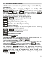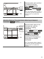
1
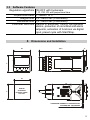
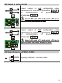
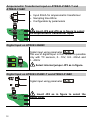
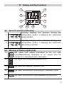
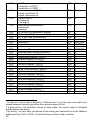
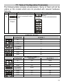
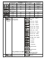
Summary
1
2
3
Introduction ........................................................................................................ 3
Model Identification............................................................................................ 3
Technical Data................................................................................................... 4
3.1
General Features........................................................................................ 4
3.2
Hardware Features..................................................................................... 4
3.3
Software Features ...................................................................................... 5
4 Dimensions and Installation............................................................................... 5
4.1
Panel Assembly.......................................................................................... 6
4.2
Electronics Removal................................................................................... 6
5 Electrical wirings ................................................................................................ 7
5.1
Wiring diagram ........................................................................................... 7
6 Display and Key Functions .............................................................................. 13
6.1
Numeric Indicators (Display) .................................................................... 13
6.2
Meaning of Status Lights (Led) ................................................................ 13
6.3
Keys.......................................................................................................... 14
7 Controller Functions......................................................................................... 14
7.1
Modifying Main Setpoint and Alarm Setpoint Values ............................... 14
7.2
Auto-Tune ................................................................................................. 15
7.3
Manual Tuning.......................................................................................... 15
7.4
Automatic Tuning...................................................................................... 15
7.5
Soft Start................................................................................................... 16
7.6
Automatic/Manual Regulation for % Output Control ................................ 16
7.7
Pre-Programmed Cycle ............................................................................ 17
7.8
Memory Card............................................................................................ 18
8 LATCH ON Functions ...................................................................................... 19
8.1
Loop Break Alarm On Amperometric Transformer................................... 21
8.2
Digital Input Functions .............................................................................. 22
8.3
Dual Action Heating-Cooling .................................................................... 23
9 Serial Communication...................................................................................... 25
10 Configuration ................................................................................................... 30
10.1 Modify Configuration Parameter............................................................... 30
11 Table of Configuration Parameters.................................................................. 31
12 Alarm Intervention Modes................................................................................ 44
13 Table of Anomaly Signals ................................................................................ 49
14 Summary of Configuration parameters............................................................ 50
1 Introduction
Thank you for choosing a Pixsys controller.
With the ATR243 model Pixsys makes available in a single device all
the resources relevant to sensor input and actuators command, in
addition to the extended power range 24…230 Vac/Vdc. With 18
sensors to select and outputs configurable as relay, SSR command,
4…20 mA and 0…10Volt, the user or retailer can reduce warehouse
stock by rationalising investment and device availability. The series is
completed with models equipped with serial communication RS485
Modbus RTU and with a loading control function via the amperometric
transformer. The configuration is further simplified by the Memory
cards which are equipped with internal battery and therefore don’t
require cabling to power the controller.
2 Model Identification
The range of ATR243 controllers comes in three versions. Refer to the
table below to easily select your preferred model.
Models available, with power 24…230 Vac/Vdc +/-15% 50/60Hz – 3VA
ATR243-20-ABC
2 relays 5A or 1 relay + 1 Ssr/V/mA
ATR243-21-ABC-T
2 relays 5A + 1 Ssr/V/mA + Rs485 +amperometric
transformer*
ATR243-31-ABC
3 relays 5A + 1 Ssr/V/mA + amperometric
transformer*
* Models with amperometric transformer input for Loop break alarm
function.
3
3 Technical Data
3.1 General Features
Displays 4 0.40 inch displays +
4 0.30 displays
Operating 0-45°C, humidity 35..95uR%
temperature
Sealing IP65 front panel (with gasket)
IP20 casing and terminals
Material PC ABS UL94VO self-extinguishing
Weight 165 g (-20ABC) / 185 g (-21/31ABC)
3.2 Hardware Features
Analogue 1: AN1
input Configurable via software
Input
Thermocouple type K, S, R, J
Automatic compensation of cold
junction from 0°C to 50°C.
Thermoresistance: PT100,
PT500, PT1000, Ni100, PTC1K,
NTC10K (β 3435K)
Linear: 0-10V, 0-20 or
4-20mA, 0-40mV, amperometric
transformer 50mA, 1024 points on
version ATR243-21/-31
Potentiometers: 6K, 150K,
Relay 2 relays (Atr243-20...-21…)
output 3 relays (Atr243-31...)
Configurable as command and/or
alarm output
SSR output 1 linear 0/4…20mA
/SSR/0…10Volt
>deselecting OUT2 relay on
ATR243-20…
Configurable as command output
or retransmission of setpoint or
process.
4
Tolerance (25°C)
+/-0.2 % ± 1 digit
for thermocouple
input, thermo
resistance and
V/mA.
Cold junction
accuracy 0.1°C/°C
Contacts 5A-250V~
Configurable:
> 4-20mA,
> 0…10Volt,
> 0-20mA.
Resolution
4000 points
3.3 Software Features
Regulation algorithms ON-OFF with hysteresis.
P, PI, PID, PD with proportional time
Proportional band
Integral time
Derivative time
Controller functions
0...9999°C or °F
0,0...999,9 sec (0 excluded)
0,0...999,9 sec (0 excluded)
Manual or automatic Tuning, configurable
alarms, protection of command and alarm
setpoints, activation of functions via digital
input, preset cycle with Start/Stop.
4 Dimensions and Installation
122.5
11
48
48
45
45
DIMA DI
FORATURA
FRONTAL PANEL
CUT-OUT
SPESSORE PANNELLO CONSIGLIATO
SUGGESTED THICKNESS
2-8mm MAX 19mm
5
4.1 Panel Assembly
Method of panel assembly and fixing of anchorage hooks.
To dismantle, use a screwdriver and slightly force the fixing hooks to
remove them from the fixing guide.
4.2 Electronics Removal
To remove the electronics, grip the front part using the two specific
side ridges.
6
5 Electrical wirings
Although this controller was designed to resist noises in
industrial environments, pease notice following safety
guidelines:
• Separate the feeder line
• Avoid
placing near
from the power lines.
units with remote control switches,
electromagnetic contactors, high powered motors and in all instances
use specific filters.
• Avoid placing near power units, particularly if phase controlled.
5.1 Wiring diagram
5
9
Q2
3
8
7
4
3
10 SUPPLY
24...230V
9 AC/DC
SSR/V/mA
-
4
PTC PT100
NTC NI100
+12
8
2
7
Q1
2
TC
6
5
11 12 13 14 15 16
10
The connections are reported below for the three models available.
1
6
V/A
1
ATR243-20ABC
5
16 +12/GND
SSR/V/mA
-
4
3
PTC PT100
NTC NI100
+12
15 ID/TA
5
10 SUPPLY
24...230V
9 AC/DC
4
8
3
14
Q2
16 +12/GND
SSR/V/mA
-
PTC PT100
NTC NI100
+12
1
7
12
Q1
2
RS485
TC
V/A
10 SUPPLY
24...230V
9 AC/DC
14
Q2
8
13
13
2
15 ID/TA
11
ATR243-21ABC-T
6
1
7
12
Q1
Q3
TC
V/A
11
6
ATR243-31ABC
7
Power
Switching power supply with extended range
24…230 Vac/dc ±15% 50/60Hz - 3VA.
AN1 Analogue Input
For thermocouples K, S, R, J.
• Comply with polarity
• For possible extensions, use a compensated
wire and terminals suitable for the
thermocouples used (compensated)
For thermoresistances PT100, NI100
• For the three-wire connection use wires with
the same section
• For the two-wire connection short-circuit
terminals 1 and 3
•
Select internal jumper JP3 as in the figure
3
2
1
For linear signals V/mA
• Comply with polarity
• Select internal jumper JP3 as in the figure
If jumpers are not properly selected,
12Vdc are not available on terminal 3 to
power the sensor.
8
Examples of Connection for linear input
For signals 0….10V
Comply with polarity
OUT : 4...20mA
IN :9...33V DC
P :0...100mbar
Pmax :3bar
T :0..70°C
OUT : 4...20mA
IN :9...33V DC
P :0...100mbar
Pmax :3bar
T :0..70°C
For signals 0/4….20mA with three-wire
sensor
Comply with polarity
A=Sensor output
B=Sensor ground
C=Sensor power
For signals 0/4….20mA with external power
of sensor
Comply with polarity
A=Sensor output
B=Sensor round
OUT : 4...20mA
IN :9...33V DC
P :0...100mbar
Pmax :3bar
T :0..70°C
For signals 0/4….20mA with two-wire sensor
Comply with polarity
A=Sensor output
C=Sensor power supply
Serial input
RS485 Modbus RTU communication
9
Relay Q1 Output
Capacity 5A/250V~ for resistive loads
Relay Q2 Output
Capacity 5A/250V~ for resistive loads
For Q2 selected as a relay output, remove
jumpers JP5 and JP7 as indicated in the figure
(Manufacturer configuration).
Connecting a load without removing the
jumpers will permanently damage the
controller
For models ATR243-21ABC-T and ATR24331ABC output Q2 is on terminals 14 and 13.
Q2 output for SSR
SSR command output 12V/30mA
Insert JP5 and JP7 and select JP9 as in
the figure to use the SSR output.
10
Q2 Output in mA or in Volt
Linear output in mA configurable using
parameters as command (Parameter
)
or
retransmission
of
process-setpoint
(Parameter
)
Insert JP5 and JP7 and select JP9 as in
figure to use the output in mA.
Linear output in Volt configurable using
parameters as command (Parameter
)
or
retransmission
of
process-setpoint
(Parameter
)
Insert JP5 and JP7 and select JP9 as in
figure to use the linear output in Volt.
Q3 Relay Output on ATR243-31ABC
Capacity 5A/250V~ resistive loads
11
Amperometric Transformer Input on ATR243-21ABC-T and
ATR243-31ABC
•
•
•
Input 50mA for amperometric transformer
Sampling time 80ms
Configurable by parameters
Insert JP4 and JP6 as in figure to select
the amperometric transformer input.
Digital Input on ATR243-20ABC
Digital input using parameter
.
The use of digital input in this version is possible
only with TC sensors, 0…10V, 0/4…20mA and
0…40mV
Select internal jumper JP3 as in figure.
Digital Input on ATR243-21ABC-T and ATR243-31ABC
Digital input using parameter
Insert JP4 as in figure to select the
digital input.
12
6 Display and Key Functions
1
2
3
7
4
6
8
9
10
5
6.1 Numeric Indicators (Display)
Normally displays the process. During the
1
configuration phase, it displays the parameter
being inserted.
2
Normally displays the setpoint. During the
configuration phase, it displays the parameter
value being inserted.
6.2 Meaning of Status Lights (Led)
3
C 1 ON when the output command is on. C1 with
C 2 relay/SSR/mA/Volt command or C1 (open) and C2
(close) for a motorised valve command.
ON
when the corresponding alarm is on.
4
A1
A2
A3
5 MAN ON when the “Manual” function is on.
6
TUN ON when the controller is running an “Autotune” cycle.
7
REM ON when the controller communicates via serial port.
13
6.3 Keys
8
•
•
Allows to increase the main setpoint.
During the configuration phase, allows to slide
through parameters. Together with the
modifies them.
•
•
•
9
Pressed after the
key it allows to increase the
alarm setpoint.
Allows to decrease the main setpoint.
During the configuration phase, allows to slide
through parameters. Together with the
modifies them.
•
•
10
•
key it
key it
Pressed after the
key it allows to decrease the
alarm setpoint.
Allows to display the alarm setpoint and runs the
autotuning function.
Allows to vary the configuration parameters.
7 Controller Functions
7.1 Modifying Main Setpoint and Alarm Setpoint Values
The setpoint value can be changed from the keyboard as follows:
Press
1
or
2
3
o
14
Effect
Value on display 2
changes
Operation
Increases or decreases the
main setpoint
Visualize alarm
setpoint on display
1
Value on display 2 Increases or decreases the
changes
alarm set point value
7.2 Auto-Tune
The Tuning procedure calculates the controller parameters and can be
manual or automatic according to selection on parameter 57
).
7.3 Manual Tuning
The manual procedure allows the user greater flexibility to decide
when to update PID algorithm work parameters. The procedure can be
activated in two ways.
• By running Tuning from keyboard:
Press the
key until display 1 shows the writing
display 2 showing
, press
, display 2 shows
TUN
The
led switches on and the procedure begins.
with
.
• By running Tuning from digital input:
Select
on parameter 61
.
On first activation of digital input (commutation on front panel) the
TUN
led switches on and on second activation switches off.
7.4 Automatic Tuning
Automatic tuning activates when the controller is switched on or when
the setpoint is modified to a value over 35%.
To avoid an overshoot, the treshold where the controller calculates the
new PID parameters is determined by the setpoint value minus the
“Set Deviation Tune” ( see Parameter 58
).
To exit Tuning and leave the PID values unchanged, just press the
key until display 1 shows the writing
with the display
showing
, press
, display 2 shows
.
The TUN led switches off and the procedure finishes.
15
7.5 Soft Start
To reach the setpoint the controller can follow a gradient expressed in
units (e.g. degree/hour).
with the desired
Set the increase value in parameter 62
units/hour; only on subsequent activation the controller uses the soft
start function.
Automatic/manual tuning cannot be enabled if the Soft start is active.
7.6 Automatic/Manual Regulation for % Output Control
This function allows you to select automatic functioning or manual
command of the output percentage.
With parameter 60
, you can select two methods.
allows you to enable the
1. The first selection
key with the writing
display two shows
.
on display 1, while
Press the
key to show
; it is
now possible, during the process display, to change the
and
. To return
output percentage using the keys
to automatic mode, using the same procedure, select
on display 2: the MAN led switches off and
functioning returns to automatic mode.
•
•
16
2. The second selection
enables the same
functioning, but with two important variants:
If there is a temporary lack of voltage or after switch-off, the
manual functioning will be maintained as well as the previously
set output percentage value.
If the sensor breaks during automatic functioning, the controller
moves to manual mode while maintaining the output percentage
command unchanged as generated by the PID immediately
before breakage.
7.7 Pre-Programmed Cycle
The pre-programmed cycle function activates by setting
in parameter 59
or
.
: the controller reaches setpoint1 basing on the
First option
gradient set in parameter 62
, then it reaches maximum power
up to setpoint2. When the process reaches maximum power, this
setpoint is maintained for the time set in parameter 63
. On
expiry, the command output is disabled and the controller displays
.
Setpoint
Hold
Setpoint 2
Natural
cooling
Max.
power
Setpoint 1
Gradient
Time
The cycle starts at each activation of the controller, or via digital input if
it is enabled for this type of functioning (see parameter 61
Second option
).
: start-up is decided only on activation of the
digital input, according to the setting of parameter 61
. On
start-up, the controller reaches setpoint 1 basing on the gradient set in
parameter 62
. When the process reaches this gradient, it is
maintained for the time set in parameter 63
. On expiry, the
command output is disabled and the controller displays
.
Setpoint
Hold
Setpoint 1
Natural
cooling
Gradient
Time
17
7.8 Memory Card
Parameters and setpoint values can be duplicated from one controller
to another using the Memory card.
There are two methods:
• With the controller connected to the power supply
Insert the memory card when the controller is off.
On activation display 1 shows
and display 2 shows
(Only if the correct values are saved in the memory card). By
pressing the
key display 2 shows
, then confirm using the
key. The controller loads the new data and starts again.
RED LIGHT: waiting for programming
GREEN LIGHT: done
LED ROSSO: acceso in programmazione
LED VERDE: programmazione eseguita
• With the controller not connected to power supply.
The memory card is equipped with an internal battery with an
autonomy of about 1000 uses.
Insert the memory card and press the programming buttons.
When writing the parameters, the led turns red and on completing the
procedure it changes to green. It is possible to repeat the procedure
without any particular attention.
18
Updating Memory Card
To update the memory card values, follow the procedure described in
the first method, setting display 2 to
so as not to load the
2
parameters on controller .
Enter configuration and change at least one parameter.
Exit configuration. Changes are saved automatically.
8 LATCH ON Functions
(potentiometer 6K) and
For use with input
(potentiometer 150K ) and with linear input (0…10V, 0...40mV,
0/4…20mA), you can associate start value of the scale (parameter 6
) to the minimum position of the sensor and value of the scale
end (parameter 7
) to the maximum position of the sensor
(parameter 8
configured as
).
It is also possible to fix the point in which the controller will display 0
(however keeping the scale range between
and
using the “virtual zero” option by setting
or
parameter 8
. If you set
)
in
the virtual zero will reset after
each activation of the tool; if you set
the virtual zero remains
fixed once tuned.
To use the LATCH ON function configure as you wish the parameter
.3
2
If on activation the controller does not display
it means no data have been
saved on the memory card, but it is possible to update values.
3
The tuning procedure starts by exiting the configuration after changing the parameter.
19
For the calibration procedure refer to the following table:
Press
1
2
3
4
Effect
Operation
Exit parameters
configuration. Display 2
Position the sensor on the
minimum functioning value
)
shows the writing
. (associated with
Set the value to minimum. Position the sensor on the
maximum functioning
The display shows
position (associated with
Set the value to maximum.
The display shows
Set the virtual zero value.
The display shows
)
To exit the standard
procedure press
.
For “virtual zero” settings
position the sensor on the
zero point.
To exit the procedure press
.
N.B.: for selection of
the procedure in
point 4 should be followed
on each re-activation.
MAX
MIN
20
ZERO
8.1 Loop Break Alarm On Amperometric Transformer
This function allows to measure load current and to manage an alarm
during malfunctioning with power in short circuit or always off. The
amperometric transformer connected to terminals 15 and 16 must be
50mA (sampling time 80ms).
• Set scale end value of the amperometric transformer in Amperes
•
on parameter 47
Set the intervention threshold of the Loop break alarm in Amperes
•
on parameter 48
Set the intervention delay time of the Loop break alarm on
•
parameter 49
You can associate the alarm with a relay by setting the parameter
,
or
as
.
If a remote control switch or SSR remains closed, the controller signals
the fault by showing
on display 2 (alternatively with a
command setpoint).
If instead the power stage remains open, or the load current is lower
than the value set on
, the controller shows
on
display.
You can display the current absorbed during the closure phase of the
power stage.
Press
1
Effect
This key enables to scroll
on display 2 the output
percentage, auto/man
selection, setpoint and
alarms.
Operation
Press
until the writing
appears on
display 1 and display 2
shows the current in
amperes (
>0).
The value is also
maintained when no
current circulates on the
load.
21
8.2 Digital Input Functions
Digital input is programmable for several functions which are useful to
simplify controller operability. Select the desired function on parameter
.
62
1.
2.
Hold function (enabled by setting
or
) allows to
lock the reading of sensors when the digital input is active
(useful for wide ranging oscillation on less significant values).
During the lock phase, display 2 flashes and shows
.
Enables/disables the autotuning function from digital input if the
parameter
is set on
.
3.
Enable regulation with
4.
Switch from automatic to manual functioning if
5.
or
.
on
Start of pre-programmed cycle
.
6.
or
.
is set
(see paragraph 7.7) with
Change setpoint function.
This function is useful where there are 2 to 4 working thresholds
required during system functioning without having to press the
arrow keys.
, by
To enable the function use the parameter
selecting the number of setpoints desired (no. thresholds
switch). They can be switched during functioning by pressing
the
key.
N.B.:
The digital input functions are not available with sensors PT100 and
NI100 on model ATR243-20ABC.
22
8.3 Dual Action Heating-Cooling
ATR243 is also suitable also for systems requiring a combined heatingcooling action.
The command output must be configured as Heating PID
(
=
and with a
greater than 0), and one of the
alarms (
,
or
) must be configured as
.
The command output must be connected to the actuator responsible
for heat, while the alarm will control cooling action.
The parameters to configure for the Heating PID are:
=
Command output type (Heating)
: Heating proportional band
: Integral time of heating and cooling
: Derivative time of heating and cooling
: Heating time cycle
The parameters to configure for the Cooling PID are the following
(example: action associated to alarm1):
=
Alarm1 selection (cooling)
: Proportional band multiplier
: Overlapping/Dead band
: Cooling time cycle
The parameter
(that ranges from 1.00 to 5.00) determines the
proportional band of cooling basing on the formula:
*
Cooling proportional band =
This gives a proportional band for cooling which will be the same as
heating band if
= 1.00, or 5 times greater if
= 5.00.
The integral time and derivative time are the same for both actions.
The parameter
determines the percentage overlapping
between the two actions. For systems in which the heating output and
cooling output must never be simultaneously active a dead band
(
≤ 0) must be configured, and vice versa you can configure an
overlapping (
> 0).
23
The following figure shows an example of dual action PID (heating= 0 and
cooling) with
= 0.
(COOL)
*
SPV
<0
PV
(HEAT)
ACTIVE
ACTIVE
COMMAND OUTPUT (HEAT)
ALARM OUTPUT (COOL)
(COOL)
*
<0
SPV
(HEAT)
PV
ACTIVE
ACTIVE
COMMAND OUTPUT (HEAT)
ALARM OUTPUT (COOL)
(COOL)
*
<0
SPV
(HEAT)
PV
ACTIVE
ACTIVE
24
COMMAND OUTPUT (HEAT)
ALARM OUTPUT (COOL)
The parameter
cycle
has the same meaning as the heating time
.
The parameter
(cooling fluid) pre-selects the proportional
and the cooling PID time cycle
band multiplier
on the type of cooling fluid:
Cooling fluid type
Air
Oil
Water
Once selected, the parameter
and
1.00
1.25
2.50
, the parameters
basing
10
4
2
,
can however be changed.
9 Serial Communication
ATR243-21ABC-T, equipped with RS485, can receive and broadcast
data via serial communication using MODBUS RTU protocol. The
device can only be configured as a Slave. This function enables the
control of multiple controllers connected to a supervisory system
(SCADA).
Each controller responds to a master query only if the query contains
. The addresses
the same address as that in the parameter
permitted range from 1 to 254 and there must not be controllers with
the same address on the same line.
Address 255 can be used by the master to communicate with all the
connected equipment (broadcast mode), while with 0 all the devices
receive the command, but no response is expected.
ATR243 can introduce a delay (in milliseconds) in the response to the
master request. This delay must be set on parameter 72
Each parameter change is saved by the controller in the EEPROM
memory (100000 writing cycles), while the setpoints are saved with a
delay of ten seconds after the last change.
NB: Changes made to words that are different from those reported in
the following table can lead to malfunction.
25
Modbus RTU protocol features
Baud-rate Can be selected on parameter 70
4800bit/sec
9600bit/sec
19200bit/sec
28800bit/sec
38400bit/sec
57600bit/sec
Format 8, N, 1 (8bit, no parity, 1 stop)
Supported WORD READING (max 20 word) (0x03, 0x04)
functions SINGLE WORD WRITING (0x06)
MULTIPLE WORDS WRITING (max 20 word)
(0x10)
The list below includes all the available addresses, where:
RO =
Read Only
R/W =
Read/Write
WO =
Write Only
26
Modbus
address
0
1
5
6
50
51
1000
1001
1002
1003
1004
1005
1006
1007
1008
1009
1010
1011
1012
1013
1014
1015
Description
Device type
Software version
Slave Address
Boot version
Automatic addressing
System code comparison
Process (with tenths of degree for temperature
sensors; digits for linear sensors)
Setpoint1
Setpoint2
Setpoint3
Setpoint4
Alarm1
Alarm2
Alarm3
Setpoint gradient
Relay status (0=off, 1=on)
Bit 0 = Q1 relay
Bit 1 = Q2 relay
Bit 2 = reserved
Bit 3 = SSR
Heating output percentage
(0-10000)
Cooling output percentage
(0-10000)
Alarms status (0=none, 1=active)
Bit0 = Alarm 1
Bit1 = Alarm 2
Manual reset: write 0 to reset all the alarms.
In reading (0=not resettable, 1=resettable):
Bit0 = Alarm 1
Bit1 = Alarm 2
Error flags
Bit0 = Eeprom writing error
Bit1 = Eeprom reading error
Bit2 = Cold junction error
Bit3 = Process error (sensor)
Bit4 = Generic error
Bit5 = Hardware error
Bit6 = L.B.A.O. error
Bit7 = L.B.A.C. error
Cold junction temperature (tenths of degree)
Read
Write
RO
RO
R/W
RO
WO
WO
RO
Reset
value
EEPROM
EEPROM
EEPROM
EEPROM
?
R/W
R/W
R/W
R/W
R/W
R/W
R/W
RO
RO
EEPROM
EEPROM
EEPROM
EEPROM
EEPROM
EEPROM
EEPROM
EEPROM
0
RO
0
RO
0
RO
0
WO
0
RO
0
RO
?
27
1016
1017
1018
1019
1020
1021
1022
1023
2001
2002
...
2072
3000
3001
3002
3003
3004
3005
3006
3007
3008
3009
3010
3011
3012
3013
3014
3015
3016
1
Start/Stop
0=controller in STOP
1=controller in START
Lock conversion ON/OFF
0=Lock conversion off
1=Lock conversion on
Tuning ON/OFF
0=Tuning off
1=Tuning on
Automatic/manual selection
0=automatic
1=manual
TA Current ON (amperes to tenths)
TA Current OFF (ampere to tenths)
1
OFF LINE time (milliseconds)
Instant Current (Ampere)
Parameter 1
Parameter 2
...
Parameter 72
2
Disabling serial control of machine
First word display1 (ASCII)
Second word display1 (ASCII)
Third word display1 (ASCII)
Fourth word display1 (ASCII)
Fifth word display1 (ASCII)
Sixth word display1 (ASCII)
Seventh word display1 (ASCII)
Eighth word display1 (ASCII)
First word display2 (ASCII)
Second word display2 (ASCII)
Third word display2 (ASCII)
Fourth word display2 (ASCII)
Fifth word display2 (ASCII)
Sixth word display2 (ASCII)
Seventh display2 (ASCII)
Eighth word display2 (ASCII)
R/W
0
R/W
0
R/W
0
R/W
0
RO
RO
R/W
RO
R/W
R/W
...
R/W
WO
R/W
R/W
R/W
R/W
R/W
R/W
R/W
R/W
R/W
R/W
R/W
R/W
R/W
R/W
R/W
R/W
?
?
0
0
EEPROM
EEPROM
...
EEPROM
0
0
0
0
0
0
0
0
0
0
0
0
0
0
0
0
0
If value is 0, the control is disabled. If different from 0, it is the max. time which can
elapse between two pollings before the controller goes off-line.
If it goes off-line, the controller returns to Stop mode, the control output is disabled
but the alarms are active.
2
By writing 1 on this word, the effects of the writing are cancelled on all the Modbus
addresses from 3001 to 3022. Control therefore returns to the controller.
28
3017
3018
Word LED
Bit 0 = LED C1
Bit 1 = LED C2
Bit 2 = LED A1
Bit 3 = LED A2
Bit 4 = LED A3
Bit 5 = LED MAN
Bit 6 = LED TUN
Bit 7 = LED REM
Word keys
(write 1 to command keys)
R/W
0
R/W
0
R/W
0
R/W
R/W
R/W
0
0
0
Bit 0 =
Bit 1 =
3019
3020
3021
3022
Bit 2 =
Word serial relay
Bit 0 = Q1 relay
Bit 1 = Q2 relay
Word SSR serial (0=off, 1=on)
Word output 0...10V serial (0…10000)
Word output 4...20mA serial (0…10000)
29
10 Configuration
10.1 Modify Configuration Parameter
For configuration parameters see paragraph 11.
Press
1
Effect
Operation
Display 1 shows
for 3
seconds.
2
or
with the 1st
digit flashing, while
display 2 shows
.
Change the flashing digit
and move to the next
one using the
3
to confirm
Enter password
key.
Display 1 shows the first
parameter and display 2
shows the value.
4
Slide up/down through
parameters
5
Increase or decrease the Enter the new data which
value displayed by
will
be
saved
on
+
releasing the keys.
pressing firstly
and
To change another
or
then an arrow key.
parameter return to point
4.
6
End of configuration
parameter change.
+
The controller exits from
Simultaneou
programming.
sly
or
30
11 Table of Configuration Parameters
The following table includes all parameters. Some of them will not be
visible on the models which are not provided with relevant hardware
features.
no.
Display
Parameter description
Select command output
type
1
Entering range
Default
(necessary to use retransmission
function)
Command
Output
ATR243-20ABC
COMMAND
ALARM 1
Q1
Q2
Q2
Q1
SSR
Q1
Q1(opens)
Q2(closes)
SSR
Q1
SSR
Q1
SSR
Q1
ATR243-21ABC-T
COMMAND
ALARM 1
ALARM 2
Q1
Q2
SSR
Q2
Q1
SSR
SSR
Q1
Q2
Q1(opens)
Q2(closes)
SSR
SSR
-
Q1
Q2
SSR
Q1
Q2
SSR
Q1
Q2
31
ATR243-31ABC
COMMAND
ALARM 1
ALARM 2
ALARM 3
Q1
Q2
SSR
Q2(opens)
Q3(closes)
SSR
SSR
SSR
Q2
Q1
Q1
Q1
Q3
Q3
Q2
SSR
SSR
SSR
Q3
-
Q1
Q1
Q1
Q2
Q2
Q2
Q3
Q3
Q3
Analog input
configuration
2
Sensor
Tc-K -260…1360°C
(Default setting)
Tc-S -40…1760°C
Tc-R -40…1760°C
Tc-J -200…1200°C
PT100 -100…600°C
PT100 -100…140°C
NI100 -60…180°C
NTC10K -40…125°C
PTC1K -50…150°C
PT500 -100…600°C
PT1000 -100…600°C
0…10Volt
0…20mA
4…20mA
0…40mVolt
Potentiometer
max 6Kohm
Potentiometer
max 150Kohm
Only ATR243-21/31ABC
Select number of
displayed decimal points
32
50mA secondary
amperometric transformer
Default
3
Decimal Point
Lower limit setpoint
4
Lower Limit
Setpoint
Upper limit setpoint
5
Upper Limit
Setpoint
6
Lower range limit An1
Lower Linear only for linear input
-999…+9999 digit∗
(degrees if temperature)
Default: 0.
-999…+9999 digit*
(degrees if temperature)
Default: 1750.
-999…+9999 digit*
Default: 0.
Input
7
Upper range limit An1
Upper Linear only for linear input
-999…+9999 digit*
Default: 1000.
Input
Automatic setting of limits
for Linear input
8
(Standard)
Latch On
Function
9
Offset
Calibration
10
Gain
Calibration
11
(Disabled) Default
(Virtual Zero Stored)
Offset calibration
Number added to
displayed value of
process (normally
corrects the room
temperature value)
Gain calibration
Value multiplied with
process value to perform
calibration on working
point
Regulation type
Action type
(Virtual Zero Initialized)
-999…+1000 digit* for linear sensors
and potentiometers.
-200.0…+100.0 tenths for
temperature sensors.
Default: 0.0.
-10.0%…+10.0%
Default: 0.0.
: Heating (N.O.) Default
: Cooling (N.C.)
: HEat Off Over Setpoint
12
Command
Reset
∗
Type of reset for state of
command contact
(always automatic in PID
functioning)
(Automatic Reset) Default
(Manual Reset)
(Manual Reset Stored)
The display of the decimal point depends on the setting of parameter
and the parameter
.
33
13
Command
State Error
14
Command
Led
15
Command
Hysteresis
16
Command
Delay
17
Command
Setpoint
Protection
18
20
21
22
Default
Default
-999…+999 digits∗
(tenths of degree if temperature)
Default: 0.0.
Command delay (only in -180…+180 seconds (tenths of
ON/OFF functioning).
second in case of servo valve).
(In case of servo valve it Negative: delay in switching off
also functions in PID and phase.
represents the delay
Positive: delay in activation phase.
between the opening and Default: 0.
closure of the two
contacts)
Allows or not to change
Default
the command setpoint
value
Proportional band
Process inertia in units
(E.g.: if temperature is in
°C)
on/off if
equal to 0. Default
1-9999 digit* (degrees if
temperature)
0.0-999.9 seconds (0 integral
Integral time. Process
disabled)
Integral Time inertia in seconds
Default: 0.
Derivative time. Normally 0.0-999.9 seconds (0 derivative
¼ the integral time
disabled)
Derivative
Default: 0.
Time
1-300 seconds
Cycle time (for PID on
Default: 10.
Cycle Time remote control switch
10/15sec, for PID on
SSR 1 sec) or servo
time (value declared by
servo-motor
manufacturer)
10-100 %
Limit of output power %
Default: 100.
Output Power
Proportional
Band
19
State of contact for
command output in case
of error
State of the OUT1 led
corresponding to the
relevant contact
Hysteresis in ON/OFF or
dead band in P.I.D.
0
Limit
∗
The display of the decimal point depends on the setting of parameter
and parameter
34
.
23
Alarm 1
Alarm 1 selection.
Intervention of the alarm
is associated with AL1
(Disabled) Default
(Absolute Alarm)
(Band Alarm)
(High Deviation Alarm)
(Low Deviation Alarm)
(Absolute Command setpoint Alarm)
(Start Alarm) Active in Run
Only ATR243-21/31ABC
24
Alarm 1 output contact
Alarm 1 State and intervention type
Output
(Cooling)
(Loop Break Alarm)
(n.o. start) Default
Normally open, active at start
(n.c. start)
Normally closed, active at start
(n.o. threshold)
Normally open, active on reaching
4
alarm
(n.c. threshold)
4
Normally closed on reaching alarm
25
Alarm 1
Reset
Type of Reset for contact
of alarm 1
(Automatic Reset) Default
(Manual Reset)
(Manual Reset Stored)
26
State of contact for alarm
Alarm 1 State 1 output in case of error
Default
Error
27
Alarm 1 Led
28
Alarm 1
Hysteresis)
4
State of the OUT2 led
corresponding to the
relative contact
Alarm 1 hysteresis
Default
-999…+999 digit∗
(tenths of degree if temperature).
Default: 0.
On activation, the output is inhibited if the controller is in alarm mode. Activates only
if alarm condition reappers, after that it was restored.
35
Alarm 1 delay
29
Alarm 1 Delay
30
Alarm 1
Setpoint
Protection
31
Alarm 2
-180…+180 Seconds
Negative: delay in alarm output
phase.
Positive: delay in alarm entry phase.
Default: 0.
Alarm 1 set protection.
Does not allow user to
modify setpoint
Default
Alarm 2 selection.
Alarm intervention is
associated with AL2
(Disabled) Default
(Absolute Alarm)
(Band Alarm)
(High Deviation Alarm)
(Low Deviation Alarm)
(Absolute Command setpoint Alarm)
(Start Alarm)
(Cooling)
(Loop Break Alarm)
Alarm 2 output contact
and intervention type
32
Alarm 2 State
Output
(n.o. start) Default
Normally open, active at start
(n.c. start)
Normally closed, active at start
(n.o. threshold)
Normally open, active on reaching
5
alarm
(n.c. threshold)
Normally closed, active on reaching
5
alarm
∗
The display of the decimal point depends on the setting of parameter
and parameter
.
On activation, the output is inhibited if the controller is in alarm mode. It activates
only if alarm condition reappears after that it was restored.
36
5
33
Alarm 2
Reset
Type of Reset for contact
of alarm 2
(Automatic Reset)
Default
(Manual Reset)
(Manual Reset Stored)
34
State of contact for alarm
Alarm 2 State 2 output in case of error
Default
Error
35
Alarm 2 Led
36
State of OUT2 led
corresponding to relative
contact
Alarm 2 hysteresis
Alarm 2
Hysteresis
Alarm 2 delay
37
Alarm 2 Delay
38
Alarm 2
Setpoint
Protection
39
Alarm 3
Alarm 2 set protection.
Does not allow operator
to change value of
setpoint
Alarm 3 selection.
Alarm intervention is
associated with AL3
Default
-999…+999 digit∗
(tenths of degree if temperature).
Default: 0.
-180…+180 Seconds
Negative: delay in alarm output
phase.
Positive: delay in alarm entry phase.
Default: 0.
Default
(Disabled) Default
(Absolute Alarm)
(Band Alarm)
(High Deviation Alarm)
(Low Deviation Alarm)
(Absolute Command setpoint Alarm)
(Start Alarm)
(Cooling)
∗
The display of the decimal point depends on the setting of parameter
and parameter
.
37
(Loop Break Alarm)
Alarm 3 output contact
and intervention type
40
Alarm 3 State
Output
(n.o. start) Default
Normally open, active at start
(n.c. start)
Normally closed, active at start
(n.o. threshold)
Normally open, active on reaching
6
alarm
(n.c. threshold)
Normally closed, active on reaching
6
alarm
Type of Reset for contact
of alarm 3
(Automatic Reset) Default
41
Alarm 3
Reset
(Manual Reset)
(Manual Reset Stored)
42
State of contact for alarm
Alarm 3 State 3 output in case of error
Default
Error
43
Alarm 3 Led
44
Defines the state of
OUT3 led corresponding
to the relative contact
Alarm 3 hysteresis
Alarm 3
Hysteresis
Alarm 3 delay
45
Alarm 3 Delay
46
Alarm 3
Setpoint
Protection
47
Alarm 3 set protection.
Does not allow the
operator to change the
value of setpoint
Activation and scale of
amperometric
Default
-999…+999 digit∗
(tenths of degree if temperature).
Default: 0.
-180…+180 Seconds
Negative: delay in alarm output
phase.
Positive: delay in alarm entry phase.
Default: 0.
Default
0
Disabled
1-200 Ampere
6
On activation, the output is inhibited if the controller is in alarm mode. It activates
only if alarm condition reappears after that it was restored.
∗
The display of the decimal point depends on the setting of parameter
and parameter
38
.
Amperometric transformer
Transformer
48
Loop Break
Alarm
Threshold
49
(Loop Break
Alarm Delay)
Default: 0.
Intervention threshold of
Loop break alarm
0.0-200.0 Ampere
Default: 50.0.
Delay time for Loop
break alarm intervention
00.00-60.00 mm.ss
Default: 01.00.
Type of cooling fluid
50
Default
Cooling Fluid
51
Proportional
Band
Multiplier
52
Proportional band
multiplier
1.00-5.00
Default: 1.00.
Overlapping/Dead band
-20.0-50.0%
Default: 0.
Cycle time for cooling
1-300 seconds
Default: 10.
(Overlap/Dea
d Band)
53
Cooling Cycle output
Time
54
Conversion
Filter
ADC filter: number of
means on analog-digital
conversions
(Disabled)
(2 Samples Mean)
(3 Samples Mean)
(4 Samples Mean)
(5 Samples Mean)
(6 Samples Mean)
(7 Samples Mean)
(8 Samples Mean)
(9 Samples Mean)
(10 Samples Mean)
Default
(11 Samples Mean)
(12 Samples Mean)
(13 Samples Mean)
(14 Samples Mean)
39
(15 Samples Mean)
55
Conversion
Frequency
Frequency of sampling of
analog-digital converter
(242 Hz)
(123 Hz)
(62 Hz)
(50 Hz)
(39 Hz)
(33.2 Hz)
(19.6 Hz)
(16.7 Hz) Default
(12.5 Hz)
(10 Hz)
(8.33 Hz)
(6.25 Hz)
(4.17 Hz)
Visualisation filter
56
Visualisation
Filter
(Disabled) Default
(First Order)
(2 Samples Mean)
(3 Samples Mean)
(4 Samples Mean)
(5 Samples Mean)
(6 Samples Mean)
(7 Samples Mean)
(8 Samples Mean)
(9 Samples Mean)
(10 Samples Mean)
Tuning type selection
57
Tune
(Disabled) Default
(Automatic)
PID parameters are calculated at
activation and change of set.
(Manual)
Launch from keys or digital input.
40
58
Setpoint
Deviation
Tune
59
Select the deviation from
the command setpoint,
for the threshold used by
autotuning to calculate
the PID parameters
Select operating mode
Operating
Mode
0-5000 digit∗ (tenths of degree if
temperature).
Default: 10.
(Controller) Default
(Programmed Cycle)
(2 Thresholds Switch)
(2 Thresholds Switch
Impulsive)
(3 Thresholds Switch
Impulsive)
(4 Thresholds Switch
Impulsive)
(Time Reset)
(Programmed Cycle
Start/Stop)
60
Automatic /
Manual
Enable automatic/manual
selection
(Disabled) Default
(Enabled)
(Enabled Stored)
61
Digital Input
Digital input functioning
(P59 selection must be
or
(Disabled) Default: 0.
(Start/Stop)
)
(Run n.o.)
(Run n.c.)
(Lock Conversion n.o.)
(Lock Conversion n.c.)
(Tune) Manual
(Automatic Manual
impulse)
(Automatic Manual
Contact)
∗
The display of the decimal point depends on the setting of the parameter
and the parameter
.
41
62
63
disabled
Increase gradient for soft 0
start
or
pre-programmed
1-9999 Digit/time∗
Gradient
cycle
(degrees/hours with display of tenths
if temperature)
Default: 0.
00.00-24.00 hh.mm
Maintenance time for
Default: 00.00.
Maintenance pre-programmed cycle
Time
64
Allows the rise gradient
User Menu and the maintenance
time to be changed from
Cycle
Programmed the user menu, in preprogrammed cycle
functioning
65
Visualization
Type
Select visualization for
display 1 and 2
(Disabled) Default
(Gradient)
(Maintenance Time)
(All)
(1 Process, 2 Setpoint) Default
(1 Process, 2 Hide after 3 sec.)
(1 Setpoint, 2 Process)
(1 Setpoint, 2 Hide after 3 sec.)
(1 Process, 2 Ampere.)
Select degree type
66
Degree
: Centigrade
Default
:Fahrenheit
67
Retransmission for
Retransmissi output 0-10V or
4…20mA.
on
(Select Jumper JP5,
JP7 and JP9).
Parameters 68 and 69
define the lower and
upper limits of the scale.
(Disabled) Default
(Volt Process)
(mA Process)
(Volt Command setpoint)
(mA Command setpoint)
(Volt Output Percentage)
(mA Output Percentage)
(Volt Alarm 1 setpoint)
∗
The display of the decimal point depends on the setting of parameter
and parameter
42
.
(mA Alarm 1 setpoint)
(Volt Alarm 2 setpoint)
(mA Alarm 2 setpoint)
(Volt A.T.)
(mA A.T.)
68
Lower Limit
Retransmissi
on
69
Upper Limit
Retransmissi
on
Lower limit range of
linear output
-999…+9999 digit∗ (degrees if
temperature)
Default: 0.
Upper limit range of
linear output
-999…+9999 digit* (degrees if
temperature)
Default: 1000.
Select baud rate for
serial communication
70
Baud Rate
Default
71
Slave
Address
72
Serial Delay
∗
Select slave address for
serial communication
1 – 254
Default: 254.
Select serial delay
0 – 100 milliseconds
Default: 20.
The display of the decimal point depends on the setting of parameter
parameter
and
.
43
12 Alarm Intervention Modes
Absolute Alarm or Threshold Alarm (
Pv
Alarm Spv
Hysteresis
parameter
>0
Time
On
Off
On
Off
Alarm
output
Hysteresis
parameter
<0
Pv
Alarm Spv
Time
On
Off
On
Off
Alarm
output
Time
Pv
Hysteresis
parameter
>0
Alarm Spv
On
Off
44
On
Off
Alarm
output
selection)
Absolute alarm with controller
in heating functioning
(Par.11
selected
)
and hysteresis value greater
than “0” (Par.28
> 0).
N.B.: The example refers to alarm 1;
the function can also be enabled for
alarms 2 and 3 on models that
include it.
Absolute alarm with controller
in heating functioning
(Par.11
selected
)
and hysteresis value less than
“0” (Par.28
< 0).
N.B.: The example refers to alarm 1;
the function can also be enabled for
alarms 2 and 3 on models that
include it.
Absolute alarm with controller
in cooling functioning
(Par.11
selected
) and hysteresis value
greater than “0” (Par.28
> 0).
N.B.: The example refers to alarm 1;
the function can also be enabled for
alarms 2 and 3 on models that
include it.
Time
Pv
Alarm Spv
Hysteresis
parameter
<0
On
On
Off
Alarm
output
Off
Absolute alarm with controller
in cooling functioning
selected
(Par.11
) and hysteresis value
less than “0” (Par.28
<
0).
N.B.: The example refers to alarm 1;
the function can also be enabled for
alarms 2 and 3 on models that
include it.
Absolute Alarm or Threshold Alarm Referring to Setpoint
Command (
selection)
Comand Spv
Hysteresis
parameter
>0
Alarm Spv
Time
On
Off
Off
Alarm
output
Absolute alarm refers to the
command set, with the
controller in heating
functioning
(Par.11
selected
)
and hysteresis value greater
than “0” (Par.28
> 0).
The command set can be
changed by pressing the
arrow keys on front panel or
using serial port RS485
commands.
N.B.: The example refers to alarm 1;
the function can also be enabled for
alarms 2 and 3 on models that
include it.
45
Band Alarm (
selection)
Pv
Alarm Spv
Hysteresis
parameter
>0
Comand Spv
Alarm Spv
Time
On
On
Off
Off
Alarm
output
Hysteresis
parameter
<0
Comand Spv
Time
On
46
On
Off
Band alarm hysteresis value
less than “0” (Par.28
<
0).
Alarm Spv
Hysteresis
parameter
<0
Off
N.B.: The example refers to alarm 1;
the function can also be enabled for
alarms 2 and 3 on models that
include it.
On
Off
Pv
On
Band alarm hysteresis value
greater than “0” (Par.28
> 0).
Off
Alarm
output
N.B.: The example refers to alarm 1;
the function can also be enabled for
alarms 2 and 3 on models that
include it.
Upper Deviation Alarm (
selection)
Pv
Alarm Spv
Hysteresis
parameter
>0
Upper deviation alarm value of
alarm setpoint greater than “0”
and hysteresis value greater
than “0” (Par.28
> 0).
Comand Spv
N.B.:
Time
On
Off
On
Alarm
output
Off
Pv
Comand Spv
Alarm Spv
Hysteresis
parameter
>0
Time
On
Off
On
Off
Alarm
output
a) The example refers to alarm 1;
the function can also be enabled for
alarms 2 and 3 on models that
include it.
b) With hysteresis less than “0”
(
< 0) the broken line moves
above the alarm setpoint.
Upper deviation alarm value of
alarm setpoint less than “0”
and hysteresis value greater
than “0” (Par.28
> 0).
N.B.:
a) The example refers to alarm 1;
the function can also be enabled for
alarms 2 and 3 on models that
include it.
b) With hysteresis less than “0”
< 0) the broken line moves
(
above the alarm setpoint.
47
Lower Deviation Alarm (
selection)
Pv
Comand Spv
Hysteresis
parameter
>0
Alarm Spv
Time
On
On
Off
Off
Alarm
output
Hysteresis
parameter
>0
Pv
Alarm Spv
Comand Spv
Time
On
On
Off
48
Off
Alarm
output
Lower deviation alarm value of
alarm setpoint greater than “0”
and hysteresis value greater
than “0” (Par.28
> 0).
N.B.:
a) The example refers to alarm 1;
the function can also be enabled for
alarms 2 and 3 on models that
include it.
b) With hysteresis less than “0”
(
< 0) the broken line moves
under the alarm setpoint.
Lower deviation alarm value of
alarm setpoint less than “0”
and hysteresis value greater
than “0” (Par.28
> 0).
N.B.:
a) The example refers to alarm 1;
the function can also be enabled for
alarms 2 and 3 on models that
include it
b) With hysteresis value less than
“0”
(
< 0) the broken line moves
under the alarm setpoint.
13 Table of Anomaly Signals
In case of malfunctioning of the system, the controller switches off the
regulation output and displays the type of anomaly.
For example the controller will signal the breakage of any connected
thermocouple by displaying
(flashing) on display. For other
notifications, see the table below.
#
E-01
E-02
E-04
E-05
Cause
What to do
Error in E²PROM cell
programming
Cold junction sensor fault or room
temperature outside of allowed
limits.
Incorrect configuration data.
Possible loss of calibration values.
Thermocouple open or
temperature outside of limits.
Call Assistance
Call Assistance
Check if the configuration parameters
are correct.
Check the connection with the
sensors and their integrity.
49
14 Summary of Configuration parameters
Date:
Installer:
Notes:
Model ATR243:
System:
Command output type selection
Analog input configuration
Number of decimal points
Lower limit setpoint
Upper limit setpoint
Lower limit range An1 only for linear
Upper limit range An1 only for linear
Automatic setting of linear input limits.
Offset calibration
Gain calibration
Regulation type
Command output reset type
Contact state for command output in case of error
Define the OUT1 led state
Hysteresis in ON/OFF or dead band in P.I.D.
Command delay
Command setpoint protection
Proportional band
Integral time
Derivative time
Cycle time
Limit of output power %
Alarm 1 selection
Alarm 1 output contact and intervention type
Reset type of alarm 1 contact.
State of contact for alarm 1 output
State of OUT2 led
50
Alarm 1 hysteresis
Alarm1 delay
Alarm 1 set protection
Alarm 2 selection
Alarm 2 output contact and intervention type
Reset type of alarm 2 contact
State of contact for alarm 2 output
State of OUT2 led
Alarm 2 hysteresis
Alarm 2 delay
Alarm 2 set protection
Alarm 3 selection
Alarm 3 output contact and intervention type
Reset type of alarm 3 contact
State of contact for alarm 3 output
State of OUT3 led
Alarm 3 hysteresis
Alarm 3 delay
Alarm 3 set protection
Activation and scale range of amperometric transformer
Intervention threshold of Loop break alarm
Delay time for Loop break alarm intervention
Cooling fluid type
Proportional band multiplier
Overlapping/Dead band
Cycle time for cooling output
Analog converter filter
Sampling frequency of analog converter
Display filter
Autotuning type selection
Command setpoint deviation for tuning threshold
Operating mode
Automatic/manual selection
51
Digital input functioning
Gradient for soft start
Cycle maintenance time
Gradient change and maintenance time by user
Display data selection
Degree type selection
Retransmission for output 0-10V or 4…20mA
Lower limit range for linear output
Upper limit range for linear output
Select baud rate for serial communication
Select slave address
Select the serial delay
52
Notes / Updates
53
54
55
PIXSYS
Via Tagliamento, 18
30030 Mellaredo di Pianiga (VE)
www.pixsys.net
e-mail: [email protected] - [email protected]
Software Rev. 1.03
2300.10.081-RevA EN 180707
*2300.10.081-A*
56