1
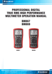
Functional Overview This section describes how to use and navigate through the basic functions of the GB1400, including: • BERT Basics • Controls, indicators and connectors • Display Formats • Outputs and Inputs Also in this section is: GB1400 User Manual • Tutorial - "Understand GB1400 instrument setup for BER testing using PRBS patterns"; • Application Note - Auto Search Synchronization with GB1400; and, • Application Example - GB700/ GB1400 Optical component test. 2-1 Functional Overview BERT Basics - GB1400 The GB1400 Generator and Analyzer together comprise a 1400 Mb/s, serial, bit error rate test system or BERT. A BERT is an instrument designed to measure the bit error rate (BER)—or more generally, the error performance—of a digital communications device, module, or system. A typical BERT application, for example, would be to measure the error performance of the electrical-to-optical (E/O) and optical-to-electrical (O/E) output modules of a high-speed fiber optic transmission system (FOTS), as shown in the figure below. GB1400 Generator CLOCK OUT GB1400 Analyzer CLOCK IN DATA OUT E/O DATA IN O/E Figure 2-1. Example, BERT Application The GB1400 is described as a serial BERT because it is designed to test one digital path at a time. The term serial also distinguishes the GB1400 from parallel BERTs, such as the Tektronix MB100, which is designed to test multiple digital signal paths simultaneously. The GB1400 Generator, also known as the transmitter or "Tx", can generate various test patterns, including pseudo-random bit sequences (PRBS) and userdefined word patterns. The Generator output consists of a two level, non-return to zero (NRZ) data signal and its associated clock signal, as illustrated in Figure 2-2. In the NRZ format, the data signal remains at either a logic "1" or logic "0" level for the entire duration of each bit time slot, except for a small transition period between time slots containing different data. The corresponding clock signal is a nominal "square wave" whose frequency defines the bit rate of the test signal. 2-2 GB1400 User Manual Functional Overview Falling edge of CLOCK in middle of DATA "eye" Rising edge of CLOCK Coincident with DATA transitions CLOCK DATA Figure 2-2. Nominal Generator NRZ Data and Clock Output Waveforms The nominal Generator clock/data phase relationship is fixed so that the falling edges of the clock signal occur in the middle of bit time slots of the data signal. The amplitude and baseline offset of the Generator's clock and data outputs are adjustable to insure compatibility with a wide range of input circuit designs and logic families including ECL, positive ECL, and GaAs. The GB1400 Analyzer, also known as the receiver or "Rx", can terminate and analyze the NRZ output of a digital device, module, or system being tested by the GB1400 Generator or an equivalent signal source. The decision voltage or threshold of the Analyzer DATA and CLOCK inputs can be adjusted to accommodate different logic families. The Analyzer can also add a variable amount of delay to the input data signal to accommodate different clock/data phase relationships at the output of the device under test. The primary measurements made by the GB1400 Analyzer are bit errors and bit error rate. GB1400 User Manual 2-3 Functional Overview Controls, Indicators and Connectors The first four figures in this section identify the controls, indicators and connectors located on the front and rear panels of the GB1400 Generator (TX) and GB1400 Analyzer (RX). gigaBERT1400 GENERATOR FREQUENCY (kHz) PATTERN OUTPUT ERROR INJECT AMPL VIEW ANGLE RATE SINGLE OFFSET MEMORY PANEL LOCK PATTERN CLOCK FREQUENCY PRBS STEP WORD WORD F1 LENGTH OUTPUT F2 F3 F4 CLEAR SET CLOCK DATA GPIB ADDR OFFSET AMPLITUDE BIT LOCAL RECALL SAVE RECALL SAVE MSB 1 2 3 4 5 6 7 INVERT DATA (D-INV) 8 REMOTE EXT OUTPUT ON INPUT OFF PATTERN SYNC CLOCK/4 CLOCK CLOCK (2) 50 Ohm 2 V Max POWER DATA DATA (1) 50 Ohm SOURCE 50 Ohm SOURCE (1) With Option 2, these outputs are 75 Ohm. (2) With Option 5, the input is ECL levels only. Figure 2-3. Front Panel, GB1400 Generator (TX) PHASE A PHASE B CLOCK/2 ERROR INJECT RS-232C DATA INHIBIT GPIB WARNING ELECTRICAL SHOCK HAZARD THIS INSTRUMENT MUST BE GROUNDED DO NOT OPEN INSTRUMENT REFER SERVICING TO QUALIFIED PERSONNEL AC-LINE DISCONNECT POWER CORD BEFORE REPLACING FUSE FOR CONTINUED FIRE PRODUCTION REPLACE ONLY WITH SPECIFIED FUSES INPUT VOLTAGE RANGE MAX LINE POWER FUSE 115 90-132V 175W 5A SLOBLO 230 180-250V 175W 5A SLOBLO AUTO SELECT FREQUENCY 47-63 Hz Figure 2-4. Rear Panel, GB1400 Generator (TX) 2-4 GB1400 User Manual Functional Overview gigaBERT 1400 ANALYZER FREQUENCY (kHz) ERROR RATE TOTALIZE ERROR HISTORY SYNC LOSS CLEAR BIT PHASE POWER DELAY/ MEMORY VIEW ANGLE PANEL LOCK PATTERN INPUT DELAY WORD LENGTH F1 PRBS ERROR DETECTION F2 F3 F4 CLEAR DISPLAY CLEAR SET SYNC GPIB ADDR CLK WORD LOCAL V-TERM V-THRESH RECALL SAVE MSB 1 REF AUDIO VOL RATE BIT 2 3 4 5 6 7 8 LOCK AUTO SEARCH DISABLE REMOTE D-INV EXT ON DATA DATA OFF POWER REFERENCE DATA CLOCK (1) PATTERN SYNC CLOCK MONITOR CLOCK DATA (1) (2) 50 Ohm, 2V MAX 50 Ohm, 1.5V MAX 50 Ohm SOURCE (1) With Option 2, this input is 75 Ohm. (2) With Option 5, the input is ECL levels only. Figure 2-5. Front Panel, GB1400 Analyzer (RX) DATA ERROR INHIBIT THRESHOLD RZ ERROR OUTPUT RS-232C PRINTER GPIB WARNING ELECTRICAL SHOCK HAZARD THIS INSTRUMENT MUST BE GROUNDED DO NOT OPEN INSTRUMENT REFER SERVICING TO QUALIFIED PERSONNEL AC-LINE DISCONNECT POWER CORD BEFORE REPLACING FUSE FOR CONTINUED FIRE PRODUCTION REPLACE ONLY WITH SPECIFIED FUSES INPUT VOLTAGE RANGE MAX LINE POWER FUSE 115 90-132V 175W 5A SLOBLO 230 180-250V 175W 5A SLOBLO AUTO SELECT FREQUENCY 47-63 Hz Figure 2-6. Rear Panel, GB1400 Analyzer (RX) GB1400 User Manual 2-5 Functional Overview Display Formats The normal display format for the Generator and Analyzer are explained below. Note that the "normal" format is simply the format of the display when not in the menu mode. Generator (TX) Display The Generator has a two-line by 24-character high-contrast liquid crystal display (LCD). The Generator display in its normal (non-menu) mode is illustrated in the figure below. Frequency (kHz) Pattern Output 1405000 PN23 2.00 V AMPL FREQ 0 ERR OFF -1.00 V OFFS Memory Figure 2-7. Generator Display in Its Normal (Non-menu) Mode The function of each field in the normal Generator display format—that is the format used when the Generator is not in the menu mode - is described below: 2-6 • The top left section of the Generator display is used to show the current frequency of the internal clock in MHz. For example a display of 6 2 2 . 0 5 0 indicates a frequency of 622.050 MHz. • The top middle section normally shows the current test pattern. For example PN23 INV indicates that the current pattern is an inverted 223-1 PRBS. • The top right section of the display shows the amplitude of the CLOCK or DATA output, depending on which output control (CLOCK or DATA) is selected. • The bottom left section of the Generator display may show either the presently selected word memory (WORD 0 ... WORD 7) or the selected frequency memory (FREQ 0 ... FREQ 9). • The bottom middle section of the display shows the currently selected Generator Pattern. • The bottom right section of the Generator display will normally show the baseline offset of the CLOCK or DATA output, depending on which output control (CLOCK or DATA) is selected. GB1400 User Manual Functional Overview Analyzer (RX) Display Like the Generator, the Analyzer has a two-line by 24-character high-contrast liquid crystal display (LCD).The Analyzer display in its normal (non-menu) mode is illustrated in the figure below. Frequency (kHz) Error Rate Totalize 1405000 5.0E-06 2410538 1.2 ns PN23 -0.05 V Delay/ Memory Figure 2-8. Analyzer Display in Its Normal (Non-menu) Mode Like the Generator, the Analyzer has a two-line by 24-character high-contrast liquid crystal display (LCD). The function of each field in the normal Analyzer display format -that is the format used when the Analyzer is not in the menu mode -is described below: GB1400 User Manual • The top left section of the Analyzer display is used to show the measured frequency of the input clock signal in MHz. For example a display of 6 2 2 . 0 5 indicates a measured frequency of 622.05 MHz. Note that the Analyzer frequency display contains five significant digits while the Generator frequency display contains six. This is because the frequency shown in the Analyzer display is a measurement result while the frequency shown in the Generator display is an instrument setup which is known with more precision. • The top middle and top right sections of the display normally show measured bit error rate and bit errors respectively. BER is expressed in exponential or "E" notation. For example, a display of 1.5E-09 indicates a measured BER of 1.5 x 10⁻⁹. The Analyzer calculates BER and counts bit errors in three modes simultaneously: Window, Test, and Totalize. The symbol in front of the BER field indicates which mode has been selected for display. Window results are preceded by a blank space, that is no symbol. Totalize results will be preceded by an ∞ (infinity) symbol. Test results will be preceded by a T, U, or R depending on the selected test mode: timed, untimed, or repeat. Refer to Chapter 4 for more information on displaying Analyzer results and starting and stopping tests. • The bottom left section of the Analyzer display can show the following setup parameters: delay in nanoseconds for the DATA or REF DATA input; the selected input termination (GND, -2V, or FLT) for the CLOCK, DATA, or REFERENCE DATA input, or the selected word memory (WORD 0 ... WORD 7), Note that DATA input delay may be set manually by the user, or automatically by the AUTO SEARCH feature. 2-7 Functional Overview 2-8 • The bottom middle section of the display shows the currently selected Analyzer pattern, for example PN23 indicates a 223-1 PRBS. This section will also indicate when input pattern inversion is enabled by displaying INV after the pattern name. • The bottom right section of the Analyzer display shows the current value of the input threshold in volts for the CLOCK, DATA, or REF DATA inputs. Note that the CLOCK and DATA input thresholds may be set manually by the user, or automatically by the AUTO SEARCH feature. GB1400 User Manual Functional Overview Outputs and Inputs This section introduces all inputs and outputs of the GB1400 Generator and Analyzer. Unless otherwise indicated, all signal inputs and outputs are equipped with SMA female connectors and have a nominal input or output impedance of 50 ohms. However, a 75 Ohm Option is available for both the Generator and Analyzer which changes nominal impedance of key inputs and outputs to 75 ohms. Note: The same term can be expressed three different ways. clock = clock bar = NOT clock DATA = DATA BAR = NOT DATA The front panel of the GB1400 TX is divided into nine sections: LCD Display Error Inject Clock Pattern Output Controls GPIB Power Switch Output Connectors Generator OUTPUT Connectors Section The OUTPUT connectors section of the Generator front panel contains the outputs listed below. OUTPUT PATTERN SYNC CLOCK/4 50 Ohm SOURCE GB1400 User Manual CLOCK CLOCK DATA DATA 50 Ohm SOURCE • CLOCK and DATA [outputs]: These two connectors comprise the main test signal output of the Generator. DATA is the NRZ output of the pattern generator and CLOCK is its corresponding clock signal. The amplitude and baseline offset of CLOCK and DATA are variable. CLOCK and DATA may be used to drive single-ended clock and data inputs, respectively. • CLOCK-BAR and DATA-BAR [outputs]: These are complimentary outputs to CLOCK and DATA. That is, CLOCK and CLOCK-BAR together can drive a differential clock input, while DATA and DATA-BAR together can drive a differential data input. These complementary outputs should be terminated with a 50 Ohm load (or a 75 Ohm load if the 75 Ohm Option is 2-9 Functional Overview installed) when not in use—that is, when the Generator is driving singledended inputs. • CLOCK/4 [output]: This is a clock signal at one quarter the frequency of CLOCK. This output may be useful when observing generator outputs using an oscilloscope that does not have the bandwidth to trigger on the CLOCK output. • PATTERN SYNC [output]: This is a pulse that occurs once per pattern frame. This output may be useful as a trigger signal when observing the Generator data output using an oscilloscope. The location of PATTERN SYNC is fixed. A pulse is generated at the start of the pattern frame. Generator CLOCK Section Controls in the CLOCK section of the Generator are used to select clock mode (internal or external) and to set up the instrument's internal clock. The CLOCK section also contains the input connector for an external clock source. These controls and input are introduced below. FREQUENCY STEP RECALL SAVE EXT INPUT (2) 50 Ohm 2 V Max 2-10 • FREQUENCY: When this key is selected (LED on), the clock up/down keys may be used to adjust the frequency of the internal Generator clock up or down. Each press of the frequency up or down key will increment or decrement frequency by the current step size. • STEP: Select this key to adjust the frequency adjustment step size from 1 kHz to 100 MHz. • SAVE: Use this key to save the present frequency into one of 10 frequency memory locations. • RECALL: Use this key to recall a previously saved frequency. • EXT: Press this key to toggle between internal clock mode (LED off) and external clock mode (LED on). • INPUT: This is an input for an external clock source. A signal must be provided to this input when clock mode is set to external. However, when clock mode is internal, any signal appearing at this input will be ignored. GB1400 User Manual Functional Overview Generator OUTPUT Section The controls shown below are used to set up the Generator's clock and data outputs. OUTPUT CLOCK DATA OFFSET AMPLITUDE INVERT DATA (D-INV) GB1400 User Manual • CLOCK: Use this key to select clock amplitude and offset set up mode. • DATA: Use this key to select data amplitude and offset set up mode. • AMPLITUDE (↑ , ↓ ): Use these up/down keys to adjust clock or data output amplitude. • BASELINE OFFSET (↑ , ↓ ): Use these up/down keys to adjust clock or data baseline offset. • INVERT DATA: Use this key to toggle between output data inverted (LED on) and non-inverted (LED off) mode. 2-11 Functional Overview Generator Rear Panel The rear-panel of the Generator contains the auxiliary signals, remote control, and AC-power inputs shown below. See the appendix for instruction on how to set up the RS-232 and GPIB ports, and general information on using external controllers with the Generator. PHASE A PHASE B CLOCK/2 ERROR INJECT DATA INHIBIT • PHASE A: An SMA connector provides signal outputs for DATA Phase A, DATA Phase B, and CLOCK/2. These phase-shifted data patterns provide signals suitable for MUX/DEMUX testing. • PHASE B: : An SMA connector provides signal outputs for DATA Phase A, DATA Phase B, and CLOCK/2. These phase-shifted data patterns provide signals suitable for MUX/DEMUX testing. • CLOCK/2: : An SMA connector provides signal outputs for DATA Phase A, DATA Phase B, and CLOCK/2. These phase-shifted data patterns provide signals suitable for MUX/DEMUX testing. • ERROR INJECT: A signal applied to this input may be used to control error injection when the Generator is in the external (EXT ERR) injection mode. One error will occur for each rising edge of this signal. • DATA INHIBIT: A signal applied to this input may be used to asynchronously gate off the data outputs of the Generator. • RS-232C [input/output]: A two-way serial port that may be connected to an external controller or serial printer. • GPIB [input/output]: An IEEE-488 standard I/O port that may be connected to a GPIB compatible controller. This port is not compatible with stand-alone GPIB printers. • AC LINE [power input]: This is the AC power input connector for the Generator. Changing the Line Fuse 1. Disconnect the AC line cord. 2. Slide the fuse cover upwards and remove the fuse. 3. Install the correct line fuse into the holder. 4. Close the fuse cover. 5. Plug in the line cord. Allow at least two inches of clearance for the rear panel fan opening and at least one inch of clearance for the top of the unit. This assures proper cooling of the unit. Do not operate the Generator on its rear side. 2-12 GB1400 User Manual Functional Overview Analyzer INPUT Section The INPUT section of the Analyzer front panel contains the test signal NRZ data and clock inputs shown below. DATA • DATA REFERENCE DATA CLOCK CLOCK CLOCK and DATA [inputs]: These two inputs comprise the main test signal input to the Analyzer. DATA is the main NRZ data input to the Analyzer pattern detector and CLOCK is its corresponding clock signal. Both inputs have selectable input terminations. In addition, a variable amount of delay may be added to the DATA input to properly phase-align the clock and data signals. CLOCK and DATA may be used to terminate singled-ended clock and data outputs, respectively. For single-ended applications, the DATA input threshold is programmable. This requires an external cable connection from the rear panel DATA THRESHOLD output to the unused DATA input. Only the unused DATA input needs the threshold signal. The CLOCK input is self-biasing for single-ended applications. GB1400 User Manual • CLOCK-BAR and DATA-BAR [inputs]: These are complimentary inputs to CLOCK and DATA. That is, CLOCK and CLOCK-BAR together comprise a differential clock input, while DATA and DATA-BAR together comprise a differential data input. When the Analyzer is connected to singled-ended clock and data signals, these inputs are not used. • REFERENCE DATA [input]: This is an input for a reference data signal. When the external reference mode is selected (LED in EXT key is on), the signal appearing at the REF DATA input will be used as the reference signal to perform bit error analysis instead of a (reference) pattern generated by the Analyzer's error detection circuit. Note that REF DATA uses the same clock signal as DATA, however different amounts of delay can be added to the DATA and REF DATA inputs to account for phase differences between the two signals. 2-13 Functional Overview Analyzer MONITOR Section The MONITOR section of the Analyzer front panel contains the auxiliary outputs shown below. These outputs may be used to monitor the test signal as seen by the Analyzer. PATTERN SYNC MONITOR CLOCK DATA 50 Ohm SOURCE 2-14 • CLOCK [output]: A buffered copy of the clock signal received by the Analyzer. • DATA [output]: A regenerated (re-clocked) version of the data signal received by the Analyzer. • PATTERN SYNC [output]: A train of pulses that occur once per pattern frame. This output may be used to trigger an oscilloscope to view the beginning (first bit/byte) of the data pattern. GB1400 User Manual Functional Overview Analyzer Rear Panel The rear-panel of the Analyzer contains the auxiliary signal, remote control, printer, and AC-power inputs shown below. See the appendix for instruction on how to set up the RS-232 and GPIB ports, and general information on using printers and external controllers with the Analyzer. DATA ERROR INHIBIT THRESHOLD RZ ERROR OUTPUT PRINTER RS-232C GPIB • DATA THRESHOLD OUTPUT: The programmed threshold voltage is set via the front panel. Connect to DATA BAR input for single-ended applications. • ERROR INHIBIT INPUT: A signal applied to this input may be used to asynchronously gate on/off the error detection function of the Analyzer. That is, while the signal at this input is low, errors are counted. While it is high, error counting is inhibited. • RZ ERROR OUTPUT: One pulse will be generated at this output for each bit error detected. May be connected to an external recording device, for example, to log the exact times that errors occur. • PRINTER [output]: A one-way port that may be connected to a "parallel printer"—that is, any printer compatible with the parallel port (LPT1 etc.) of an IBM-compatible PC. • RS-232-C [input/output]: A two-way serial port that may be connected to an external controller (e.g. a PC or workstation) or to a serial printer. • GPIB [input/output]: A two-way, IEEE-488 compatible I/O port that may be connected to an external controller via a GPIB cable. Changing the Line Fuse 1. Disconnect the AC line cord. 2. Slide the fuse cover upwards and remove the fuse. 3. Install the correct line fuse into the holder. 4. Close the fuse cover. 5. Plug in the line cord. Allow at least two inches of clearance for the rear panel fan opening and at least one inch of clearance for the top of the unit. This assures proper cooling of the unit. Do not operate the Analyzer on its rear side. GB1400 User Manual 2-15 Functional Overview Connectors, Terminations, and Levels Tables 2-1 and 2-2 below summarize the physical interface characteristics of all GB1400 Generator and Analyzer inputs and outputs. Table 2-1. Generator (TX) Inputs and Outputs Connector Label Signal Type Location Connector Type Impedance, amplitude, and offset DATA output OUTPUT section SMA, female 50 Ohm, see NOTE 1, variable amplitude and offset CLOCK output OUTPUT section SMA, female 50 Ohm, see NOTE 1, variable amplitude and offset DATA-BAR output OUTPUT section SMA, female 50 Ohm, see NOTE 1, variable amplitude and offset CLOCK-BAR output OUTPUT section SMA, female 50 Ohm, see NOTE 1, variable amplitude and offset CLOCK/4 output OUTPUT section SMA, female 50 Ohm, 200mV into 50Ω PATTERN SYNC output OUTPUT section SMA, female 50 Ohm, 200mV into 50Ω CLOCK INPUT input CLOCK section SMA, female 50 Ohm, 2V max, see NOTE 2 DATA INHIBIT input rear panel BNC, female 50 Ohm, ECL ERROR INJECT input rear panel BNC, female 50 Ohm, ECL RS-232 I/O rear panel 25 pin, D type RS-232C standard levels and impedance GPIB I/O rear panel GPIB IEEE-488 standard levels and impedance Note 1: A 75-Ohm version of the GB1400 is an option. Note2: BURST Mode units require ECL-level inputs and are terminated with 50-Ohms to -2V. 2-16 GB1400 User Manual Functional Overview Table 2-2. Analyzer (RX) Inputs and Outputs Connector Label Signal Type Section Connector Type Impedance, threshold, and delay DATA/DATA BAR Input INPUT SMA, female 50 Ohm, see NOTE 1, variable threshold and delay. Selectable termination: GND, -2 V, AC CLOCK/CLOCK BAR Input INPUT SMA, female 50 Ohm, see NOTE 1, fixed threshold. Selectable termination: GND, -2 V, AC REF DATA Input INPUT SMA, female 50 Ohm, ECL, variable delay, selectable termination GND, -2V, AC PATTERN SYNC output MONITOR SMA, female 50 Ohm, 200mV into 50Ω CLOCK output MONITOR SMA, female 50 Ohm, 200mV into 50Ω DATA output MONITOR SMA, female 50 Ohm, 200mV into 50Ω ERROR INHIBIT INPUT input rear panel BNC, female 50 Ohm, ECL RZ ERROR OUTPUT output rear panel BNC, female 50 Ohm, 200mV into 50Ω PRINTER output rear panel 25-pin, D male Compatible with PC parallel printers RS-232C I/O rear panel 25-pin, D male RS-232 levels and impedance GPIB I/O rear panel GPIB IEEE-488 standard levels and impedance Note 1: A 75-Ohm version of the GB1400 is an option. GB1400 User Manual 2-17 Functional Overview Controls and Indicators All of the controls, indicators, inputs, and outputs found on the Generator or Analyzer front or rear panels are discussed in the following section. Power Switches The ON/OFF power switch is located on the left side of the test instrument below the LCD screen. The power switch switches the 120/240 VAC to the system power supply. When off, a Battery backup circuit powers the non-volatile RAM. Unit Mounting The GB1400 is designed to be placed: (1) flat on a level surface, capable of supporting its weight, or (2) angled from the surface with the rotating carrying handle. To change the handle's orientation, press both handle-locking buttons (located at the hubs of the handle), rotate the handle to the desired angle, and release the buttons. The handle will click into a locked position. Assure that the handle is locked before placing the unit on a work surface. A Rack mounting option is available for installation of the unit into a 19" rackmount. The rack height for the GB1400 is 7 inches (four RMU). Unit Cooling The rear panel fan openings must be kept clear for proper cooling of the unit. Allow a minimum of two (2) inches of rear panel clearance, and one (1) inch of top clearance, while operating the unit. View Angle and Panel Lock Keys The PANEL LOCK and VIEW ANGLE keys are located near the top, left side of the front panel. • VIEW ANGLE: Use this key to select the optimum LCD viewing angle. • PANEL LOCK: Use this key to "lock" and "unlock" the front panel. While the front panel is locked, all keys that can cause setup changes are disabled. This feature can help prevent accidental loss of data when performing longterm or critical tests. RESET to Factory Default To return the Generator or Analyzer to factory default settings, turn the instrument OFF and then re-power it while pressing and holding the VIEW ANGLE, MSB 1, and (PATTERN) CLEAR keys at the same time. Release these keys after the message Default Setup appears in the display. 2-18 GB1400 User Manual Functional Overview GPIB Section Controls There are two keys in the GPIB section: • ADDR: Key used to set GPIB address in the range 0 to 30. • LOCAL: The LED in this key indicates whether the instrument is in the local mode (LED off) or remote mode (LED on). If the LED is on, you can return the instrument to local mode by pressing the LOCAL key. Note that these two keys are used only when operating the instrument via its GPIB port. For more information on the GPIB port and remote control in general, see the appendix. For detailed descriptions of all remote commands, see the appendix. GB1400 User Manual 2-19 Functional Overview Pattern Controls and Function Keys The PATTERN section of both the Analyzer and Generator front panels contains two basic types or groups of controls: "pattern" and "function". The four function or "soft" keys—F1, F2, F3, and F4—have different functions depending on the current mode of the instrument. A primary function of these controls is to access and navigate the menu system. Pattern controls, which includes all other controls in the PATTERN section, are used to select edit, save, and recall test patterns. WORD LENGTH F1 PRBS F2 CLK WORD RECALL SAVE MSB 1 2 3 F3 F4 CLEAR SET REF 4 5 6 7 8 EXT 2-20 • PRBS: Press this key, and then the pattern up/down keys to select a PRBS pattern. • WORD: Press this key either to select a word or ROM pattern or to edit the current word pattern. • SAVE and RECALL: Use these keys to save and recall user-created word patterns to and from non-volatile memory. The standard GB1400 can store up to ten 16-bit or short word patterns. When equipped with the 1-Mbit option, the GB1400 Generator and Analyzer can store up to ten (10) 65-kbit patterns, depending upon the buffer size set for word memory. • WORD LENGTH: Press this key and then the up/down keys, to adjust the length of the current word pattern. • (↑ ↑ ,↓ ↓ ): These are the pattern up/down keys. Their effect depends on which of the above pattern keys has been selected. • MSB 1 to 8: Use these keys to edit the displayed byte in the current word pattern. Each key will toggle one bit in the displayed byte. • CLEAR: Pressing this key forces all bits in the displayed byte to 0. • SET: Pressing this key forces all bits in the displayed byte to 1. GB1400 User Manual Functional Overview Function (Soft) Keys (F1, F2, F3, and F4) Menu Functions: The primary use of the function keys in the Generator and Analyzer is to access and navigate each instrument's menu system. F1 may be thought of as the main menu key. Pressing F1 will display the instrument's first level menu. Once inside the menu system, you may use the F1, F2, F3, and F4 keys to select different menus, or to make choices within a selected menu. Note that pressing the F1 key enough times will always get you out of the system. See Chapter 3 - Reference for an explanation of each Generator and Analyzer menu. Analyzer Inputs These function keys provide signal inputs and control of parameters (Input Termination, Threshold, Logic Polarity and Data/Clock Phase Delay) for DATA, Ref DATA, and CLOCK. Selecting DELAY, V-TERM or V-THRS permits the INPUT Up/Down keys to vary the Input parameters for DATA, as described below. Holding the Up/Down key repeats the function five times a second. Function key F2 (CLOCK) permits the V-TERM key to vary the Input parameters for CLOCK. Function key F3 (Ref DATA) permits the DELAY, V-THRS, and V-TERM keys to vary the Input parameters for Reference DATA. DELAY - Pressing DELAY selects Input Data Delay adjust mode. The Input Data signal can be delayed over the range 0.0 nS to 3.9 nS in sub-nanosecond steps. The delay is modified with the INPUT Up/Down keys. The current Delay is displayed on the lower left side of the LCD. An illuminated Delay LED light indicates that the unit's DELAY can be modified by the Up/Down arrow keys. V-TERM - Pressing V-TERM selects V-termination mode. The input termination voltage for Input Data is selectable between 0V, -2.0V, and AC. 2.0V mode provides active termination for ECL and GaAs signals. AC mode allows RF termination. An illuminated V-TERM LED light indicates that the input termination can be modified by the Up/Down arrow keys. V-THRS - Pressing V-THRS selects V-Threshold mode. The Input Data threshold is variable over the range of -1.5V to +1V in 50 mV steps. The currently selected threshold voltage is displayed in the lower right side of the LCD display. An illuminated V-THRS LED light indicates that the threshold voltage can be modified by the Up/Down arrow keys. The Data threshold voltage is available at the Analyzer rear panel SMA jack labeled DATA THRESHOLD. Print Setup Function (Analyzer only): You can print a report showing the current setup of the Analyzer by pressing the F4 key. This function, however, is not active in the menu mode. GB1400 User Manual 2-21 Functional Overview Generator ERROR INJECT Section Controls in the ERROR INJECT section are used to set up the Generator's error injection function. ERROR INJECT RATE SINGLE 2-22 • RATE: Press this control one or more times to select an internal error inject rate, or the external error inject mode. • SINGLE: When the error inject function is set to single (ERR OFF), press this key to inject single errors. Or, when the error inject function is set to an internal rate, or to external, use this key to turn error injection off. Note that you could then press the RATE key to turn error injection back on at the same rate as before. • Error Inject (LED): The LED in the ERROR INJECT section will flash once for each injected error. GB1400 User Manual Functional Overview Analyzer INPUT Section The controls shown below are used to set up the Analyzer clock and data inputs. INPUT DELAY V-TERM V-THRESH D-INV EXT DATA DATA REFERENCE DATA CLOCK (1) CLOCK (1) (2) 50 Ohm, 2V MAX 50 Ohm, 1.5V MAX • DELAY: Press this key to add delay to the DATA or REF DATA inputs to adjust the clock/data phase relationship. Note that the Auto_Search function will automatically set data delay to a value which provides the maximum noise immunity, that is so that the active (falling) edge of the clock falls in the middle of data bit time slots. • V-THRESH: Press this key to set the input decision threshold for the DATA, CLOCK, and REF DATA inputs. Note that threshold does not apply when differential operation is selected. Function keys F2 and F3 are OFF when programming data. Function key F3 is ON when programming REF DATA. • V-TERM: Press this key to select the input terminations for the DATA, CLOCK, or REF DATA inputs. Available selections are: (GND, -2 V, or AC). See table below. • D-INV: Press this key to select either the data non-inverted (LED off) or data inverted (LED on) mode. • EXT: This is an input for an external data reference signal. NOTE: Use the F2 and F3 function keys to determine which input will be affected by the DELAY, V-THRESH, and V-TERM controls as follows: GB1400 User Manual F2 F3 Affected Input off off DATA on off off on CLOCK REF DATA on on not allowed 2-23 Functional Overview Analyzer Error History Section SYNC LOSS CLEAR BIT PHASE POWER 2-24 SYNC LOSS The SYNC LOSS LED is lit when the unit is not synchronized, it will remain lit until cleared by the user. BIT The BIT LED is lit when bit errors occurs, and remains lit until it is cleared by the user. PHASE The PHASE LED is lit when the guaranteed setup or hold time of the GB1400 input decision circuit is violated. This indicates to the user that the errors that are occurring may be due to input clock/data timing or signal level. POWER The POWER LED is lit when the unit powers up. It remains lit until it is cleared by the user. It is used to indicate that the unit lost power during a long term (overnight) test. GB1400 User Manual Functional Overview Analyzer ERROR DETECTION Section The ERROR DETECTION section contains test setup and display controls. ERROR DETECTION DISPLAY CLEAR AUDIO VOL RATE SYNC LOCK AUTO SEARCH DISABLE • DISPLAY SELECT: Use this control to select which results are displayed in the BER the Bit Error fields. The options are Window, Totalize, or Test. • CLEAR: Press this key to clear previous results and to start/stop timed tests. • AUDIO VOL (↑ , ↓ ): Use these keys to increase or decrease the volume of the Analyzer's error beeper function. • AUDIO RATE (↑ ↑ , ↓ ): Use these keys to increase or decrease the error rate threshold of the beeper function. Selections are 1E-x, where x = 2, 3, ... 16. Analyzer SYNC Controls The ERROR DETECTION section contains the following SYNC controls which are used to set up the Analyzer's automatic synchronization functions: • AUTO SEARCH: Press this key to enable (LED on) or disable (LED off) AUTO SEARCH. With AUTO SEARCH enabled, each time BER goes above the synchronization threshold (LOCK LED turns off) the Analyzer will automatically attempt to: 1. set the decision level for the DATA inputs, 2. set input DATA delay, 3. determine which PRBS or short word pattern is being received, and 4. determine if the pattern is inverted or not. GB1400 User Manual • DISABLE: Use this key to enable or disable automatic pattern resynchronization. If DISABLE is off, then the Analyzer will automatically try to resynchronize its pattern detector (by looking for a new pattern alignment) when BER goes above the current synchronization threshold. If DISABLE is on, the Analyzer will not attempt to resynchronize regardless of the BER. This allows for very high BER measurements. • LOCK (indicator): This indicator turns ON when BER is less than the current synchronization threshold, and OFF when BER is greater than or equal to this threshold. 2-25 Functional Overview Burst Mode Option The standard GB1400 operates over a clock frequency range of 1 Mbit/s to 1400 Mbit/s. The GB1400 TX has an internal clock source than has a range of 1 MHz to 1400 MHz. It also has a provision for using an external cock source of the same frequency range. When using the external clock source, it must be applied continuously without interruption. The GB1400 RX also requires that, at all times during the test, a clock signal within the 1 Mbit/s to 1400 Mbit/s frequency range be continuously applied. If the external lock signal should be removed , or go below 1 MHz for any reason during the test, the RX will register OUT of SYNC as soon as the clock signal is reapplied. This condition will initiate a resynchronization of the receiver and restart any tests. For the Burst Mode option, the GB1400 RX has been modified to work normally or in Burst Mode from 150 kHz to the normal 1400 MHz upper limit. The RX CLOCK and CLOCK BAR inputs have been modified for DC operation. This modification requires the removal of any blocking capacitors in the input path. The removal of the capacitors limits the allowable input signal to ECL levels only. Levels other than ECL may damage the input circuitry. The three standard clock input termination selections of GND, AC, and -2V are still present. The Clock may be used either differentially or single-ended. To use a singleended clock input, connect the clock input to the CLOCK input connector. XXXXXX Verify the next sentence XXXXXX Connect DC bias voltage of -1.3 VDC to the CLOCK BAR input connector, or vice versa. XXXXXXX These and other changes will now allow the receiver to maintain synchronization whenever CLOCK and DATA are synchronously stopped and started during a test pattern, providing there has not been a bit slip between CLOCK and DATA. In both the TX and RX, there can be any length of time that both CLOCK and DATA are off, and the minimum CLOCK/DATA applied can be as low as a single cycle, providing the minimum of 714 pS and maximum of 667 µs clock period restrictions are observed. Similar TX circuit changes allow the TX DATA and CLOCK outputs to follow, cycle by cycle, the input from a bursted External Clock Input. This means that the TX can be used in a start-stop, or "Burst Mode". For every clock cycle into the External Clock Input, there will be the same number of clock cycles and data bits output through the clock and data outputs. The time between clock cycle inputs is unrestricted and can be any length of time. The number of clock cycles can be any number from continuous to a single cycle. During the time there is no clock input to the External Clock Input, the internal code generator is idle (not running). Each clock cycle steps the code generator by one bit. Clock cycle period must not be more than 667 µs (150 kHz) nor less than 714 pS (1400 MHz). 2-26 GB1400 User Manual Functional Overview Burst Mode Usage The Burst Mode option of the GB1400 will find usage in applications where traditional BERTs cannot operate. As indicated earlier on this section of the Burst Mode option, traditional BERTs require a continuous CLOCK and DATA signal with no interruption. Should interruptions occur, the RX will resynchronize or indicate errors that actually did not occur due to the asynchronous re-start. There are communications and telemetry systems that do no necessarily send data continuously. These systems send data in "bursts" with variable times of inactivity between bursts. Traditional BERTs cannot accurately check these systems, especially if the bursts are of short duration. A traditional BERT may require more bits than are available in the burst to (re)synchronize. Even if the bursts are large, many bits in the burst would not be checked during the (re)synchronization procedure. In Burst Mode, the GB1400 RX will follow the input CLOCK and DATA without regard for inactive time between bursts. The only requirement is that there be no bit slips between the CLOCK and DATA at the TX or UUT and there be a clock cycle for every DATA bit received. Specifications for Burst Mode GB1400 User Manual • Maximum time between bursts - no restriction • Minimum time between bursts - one clock period • RX Clock Input - ECL level only; User-selectable termination 50 Ohms to 2V, GND, or AC; Minimum rate during burst - 150 kbit/s; Maximum rate during burst - 1400 Mbit/s • RX Auto Search restriction - Below 500 kbit/s, the Auto Search function can take a very long time due to code word search. Finding both Threshold and Delay is rapid, but Data Pattern search is lengthy. Because of this, the user should use Manual Search Mode to keep synchronization time as low as possible. • Restriction on other options - None 2-27 Tutorial Basic BERT testing with the GB1400 A critical element in digital transmission systems is how error-free its transmissions are. This measurement is made by a bit-error-rate tester (BERT). The GB1400 Generator (Tx) and Analyzer (Rx) are designed to operate at bit rates up to 1400 Mb/s. These portable instruments provide PRBS or User Defined Patterns (up to 1Mbit deep) for high speed BERT testing. Objective of Tutorial Understand GB1400 instrument setup for BER testing using PRBS patterns. Procedure This tutorial programs the GB1400 Generator to provide PRBS clock and data signals for the Analyzer. Using AUTO-SEARCH features, the Analyzer will synchronize to the incoming PRBS test pattern. Bit Error Rate (BER) measurements will be performed on both good (error-free) and bad (user injected faults) data streams. Key Feature of Tutorial This lab demonstrates the use of AUTO-SEARCH Synchronization. Equipment Required Description Qty Part Number Source GB1400 Generator 1 GB1400 Tx Tek GB1400 Analyzer 1 GB1400 Rx Tek 50Ω Coax SMA cables, 1 meter length, male to male 3 174-1341-00 Tek Note - Special Attention Needed GB1400 User Manual • Connecting the Generator’s clock output to the Analyzer’s not-clock (clockbar) input • Connecting the Generator’s data output to the Analyzer’s not-data (data-bar) input • Changing Generator’s CLOCK amplitude/offset when lab calls for adjustments to DATA signals • Failure to connect the external DATA THRESHOLD cable from rear of unit to NOT_DATA input. 2-28 Tutorial Instrument Connections and Controls Data Threshold connection (required for single-ended signals) GB1400 Analyzer (Receiver) DATA CLOCK GB1400 Generator (Transmitter) CLOCK DATA CLOCK 1. DATA Setup units with default settings Note: Resetting the unit to factory defaults is used infrequently. It helps simplify instructions on this beginners lab. A customer would not normally do this as they would loose their stored setups. To reset the units to their factory default setting, you must hold down three separate keys while turning on the front panel power switch. Power the Generator while pressing and holding its VIEW ANGLE, MSB 1 and (PATTERN) CLEAR keys simultaneously. Release the key after the message Default Settings appears in the display. Repeat this procedure with the Analyzer. This will force both the Generator and Analyzer to power up using factory default settings. GB1400 User Manual 2-29 Tutorial 2. Connect the Generator to the Analyzer. Connect the generator and analyzer as shown below. The generator CLOCK output connects to the analyzer CLOCK input. The generator DATA output connects to the analyzer DATA input. The rear panel THRESHOLD output on the Rx connects to the Receiver NOT-DATA input on the front panel. Terminate the generator NOT_CLOCK and NOT_DATA signals with the 50Ω terminators located on the front panel of the generator. rear panel threshold output GB1400 TX GB1400 RX clk clk data data data data clk clk data clock Note: Do not mix up the clock, not_clock, data, and not_data signals or tutorial results will be different. 3. Setup Generator for PRBS-23 Mode. Locate the controls in the OUTPUT box of the Generator. Setup the Generator clock and data outputs as follows: Set this parameter DATA amplitude. …to this value …using this procedure. 1 volts Press the DATA key. The LED within the switch should be lit. Press AMPLITUDE up/down keys until data amplitude is set to 2.00V. DATA baseline offset CLOCK amplitude -0.5 volt Press BASELINE OFFSET up/down keys until data baseline offset is set to -0.50V. 1 volts Press CLOCK. (the LED within switch should be lit). Press AMPLITUDE up/down keys until clock amplitude is set to 2.00V. CLOCK baseline offset 2-30 -0.5 volt Press BASELINE OFFSET up/down keys until clock baseline OFFSET is set to -0.50V. GB1400 User Manual Tutorial B. Locate the controls in the PATTERN box of the Generator. Make sure the PRBS button is enabled (the LED inside this switch should be ON). Set the Generator pattern to a 223-1 bit PRBS as follows: Set this parameter PRBS type …to this value PN 23 …using this procedure. Press pattern up/down arrow keys until PATTERN is set to PN 23 C. Locate the controls in the ERROR INJECT box of the Generator. Verify that the Generator ERROR RATE GENERATOR is OFF (the LED within the switch should be OFF). If the LED in the error inject RATE key is ON, then press RATE one or more times until it turns off. 4. Setup Analyzer for “AUTO-SEARCH” Operation. A. Locate the controls in the SYNC box of the Analyzer. Verify that the Analyzer AUTO SEARCH function is ENABLED. The LED in the AUTO SEARCH key should be ON. If the LED is OFF, press the AUTO SEARCH function one time until the LED is ON. At this point, verify that the green LOCK LED is ON. B. Locate the controls in the ERROR DETECTION box of the Analyzer. Zero all Analyzer error counts by pressing the CLEAR key. Confirm that the number of errors and the error rate were reset to 0 (note: error rate will start changing as more and more bits are received. After several minutes of operation, the error rate should reach 0.0E-9 ⇒ 0.0E-10 ⇒ 0.0E-11 and on). C. Locate the controls in the ERROR HISTORY box of the Analyzer. Reset all Analyzer history LEDs by pressing this CLEAR key. Confirm that all ERROR HISTORY LED’s are turned OFF. D. Locate the controls in the ERROR INJECT box of the Generator. Verify the GB1400 Analyzer can detect errors by pressing the Generator ERROR INJECT SINGLE key several times. Verify that the number of errors count displayed by the Analyzer increments each time the Generator SINGLE key is pressed. In effect you are now performing a bit error rate test on the test cables connecting the gigaBERT1400 Generator and Analyzer. In an actual BER test, gigaBERT1400 Generator clock and data outputs would be connected to inputs on a "device under test" (DUT) while gigaBERT1400 Analyzer inputs would be connected to outputs on the DUT. GB1400 User Manual 2-31 Tutorial 5. Change the PRBS pattern type These steps demonstrate one of the many benefits of our Full-Featured AutoSearch algorithm - automatic synchronization to the incoming signal by selecting the correct PRBS test pattern. A. Locate the controls in the PATTERN box of the Generator. Make sure the PRBS button is enabled (the LED inside this switch should be ON). Set the Generator pattern to a 27 PRBS as follows: Set this parameter PRBS type …to this value PN 7 …using this procedure. Press pattern up/down arrow keys until PATTERN is set to PN 7 As the PRBS pattern type is changed, the Analyzer will start searching for a match. You should see the BIT, PHASE, and SYNC LOSS LED’s turn ON in the Error History section of the Analyzer. While the Analyzer is searching for the correct PRBS type, the LOCK LED in the Error Detection Section should turn OFF. When synchronization is achieved, the LOCK LED should turn ON. B. Locate the controls in the ERROR DETECTION box of the Analyzer. Zero all Analyzer error counts by pressing the CLEAR key. C. Locate the controls in the ERROR HISTORY box of the Analyzer. Reset all Analyzer history LEDs by pressing this CLEAR key. Confirm that all ERROR HISTORY LED’s are turned OFF. D. Locate the controls in the ERROR INJECT box of the Generator. Press the ERROR INJECT SINGLE key several times. Verify that the error count displayed by the Analyzer increments each time the Generator SINGLE key is pressed. Verify the BIT LED light located in the Error History Section of the Analyzer turns on. 6. Turn off AUTO - SEARCH and change Generator Outputs These steps demonstrate one of the many benefits of our Full-Featured AutoSearch algorithm - setting the input data decision voltage to its optimum value. While the Auto-Search feature is disabled, the Generator output voltage will be adjusted to cause loss of sync. Auto-Search will then be enabled to correct this synchronization problem. A. Locate the controls in the SYNC box of the Analyzer. Disable the AUTO function by pressing the AUTO SEARCH key. The amber LED within this switch will be OFF when the Analyzer AUTO SEARCH function is DISABLED. If the LED is ON, press the AUTO SEARCH function one time to turn the LED OFF. SEARCH 2-32 GB1400 User Manual Tutorial B. Locate the controls in the OUTPUT box of the Generator. Adjust the Data amplitude and offset as follows: Caution: Adjust only the DATA signal. Do not change the CLOCK signal. Set this parameter DATA amplitude. …to this value 0.50 volts …using this procedure. Press the DATA key. The LED within the switch should be lit. Press AMPLITUDE up/down keys until data amplitude is set to 0.50V. DATA baseline offset -0.25 volts Press BASELINE OFFSET up/down keys until data baseline offset is set to -0.25V. If you examined this output data signal (voltage vs. time) on a scope, it would look similar to: ← Maximum Level +0.25 ↑ 0.5 V +0.00 -0.25 ↑ Voltage -0.50 time → -0.25 V data offset ↑ ← Optimum Threshold amplitude ↓ ← Minimum Level best value to use for THIS data threshold is ~0.00 Vdc + 0.05 Vdc You will now be manually adjusting the data input threshold for the GB1400 Analyzer. Locate the controls in the PATTERN box of the Analyzer. Make sure the LED’s in F2 and F3 are turned OFF. These switches are used when adjusting CLOCK or REF DATA input parameters. C. Locate the controls in the INPUT box of the Analyzer. Verify that the Analyzer THRESH LED is turned ON. This allows manual adjustment of the DATA Input threshold. The threshold for the selected signal (clock or data) is shown on the bottom line of the Analyzer’s alpha-numeric status display. Using the INPUT UP/DOWN keys, adjust this threshold and confirm the following actions: Note: The BER display on the Analyzer can be set to totalize, window, or test modes. When in the totalize mode, a small ∞ (infinity) symbol will be displayed before the BER error rate. Use totalize mode for this tutorial exercise. Press the ERROR DETECTION DISPLAY key several times to setup the analyzer for totalize mode.. GB1400 User Manual 2-33 Tutorial Set DATA THRESHOLD to this value Verify these results on the Analyzer Press the ERROR DETECTION and ERROR HISTORY “CLEAR KEYS”, then confirm: -0.50 volts SYNC LOSS and BIT LED’s are ON SYNC LOCK LED Comments Data signal not detected. Selected threshold is below the minimum level of your data signal. is OFF ERROR RATE display shows “NO DATA” or a 50% Error Rate. Approximately -0.30 volts to Press the ERROR DETECTION and ERROR HISTORY “CLEAR KEYS”, then confirm: SYNC LOSS BIT should turn OFF and PHASE LED’s should turn ON You are starting to detect the data signal. Selected threshold is near the minimum level of your data signal. Data threshold is NOT CORRECT and you should expect BER errors. -0.25 volts SYNC LOCK LED should turn ON Press the ERROR DETECTION and ERROR HISTORY “CLEAR KEYS”, then confirm: +0.00 volts SYNC LOSS BIT should turn OFF and PHASE LED’s should turn OFF SYNC LOCK LED should turn ON Data signal fully detected. Selected threshold is at an optimum value for the input data signal. This is typically = 1/2*[max level - min level]. Signal levels detected above this threshold are considered a logical “1” and signal levels below this threshold are considered a logical “0”. ERROR RATE display shows NO BER ERRORS equivalent to a rate of 0.0E-9 or better. Press the ERROR DETECTION and ERROR HISTORY “CLEAR KEYS”, then confirm: +1.00 volts SYNC LOSS and BIT LED’s are ON SYNC LOCK LED Data signal not detected. Selected threshold is above the maximum level of your data signal. is OFF ERROR RATE display shows “NO DATA” or a 50% Error Rate 2-34 GB1400 User Manual Tutorial D. Locate the controls in the SYNC box of the Analyzer. Verify that the AUTO SEARCH function is ENABLED. The LED in the AUTO SEARCH key should be ON. If the LED is OFF, press the AUTO SEARCH function one time to turn the ON. At this point, verify that the green LOCK LED is ON. The Analyzer will now search and calculate a new data threshold. What is the value of the threshold selected by Auto-Search? You should expect to see this threshold value within a few hundred millivolts of the “data signal mid-point (or optimum threshold). This Concludes the Tutorial. GB1400 User Manual 2-35 Applications Application Note Method For Very Fast Automatic Receiver Synchronization And Eye Width Measurement Two Auto Search Synchronization Methods This application note describes two Auto Search synchronization methods used in the GB1400 Bit Error Rate test set. The criteria and sequence of events for the two methods are compared and the differences are described. Auto Search is the feature that the GB1400 uses to describe its method of automatic setup and synchronization perform the following functions, but in different ways and with differing results depending on the type of data and its quality. • Analysis of the input data signal amplitude to select the correct threshold voltage. • Determine the timing skew between the clock and data signals and automatically optimize it. • Determine the timing skew between the clock and data signals and automatically optimize it. • Measure the data eye width. So that the following explanations are clear, let us first define some terms. V–THRESHOLD This is the absolute DC level above which GB1400 Receiver will declare a data bit value of “1” (HIGH). Below this value, it is considered to be a “0” (LOW). DELAY This is the timing difference (skew) between ideal timing and actual timing between the incoming clock and data. Ideal timing will place the falling edge of the clock signal in the center of the data bit. Any deviation from the ideal should, when possible, be corrected by delaying either the clock or the data (as in the GB1400 Receiver) in relation to each other. 2-36 GB1400 User Manual Application Note - Auto Search Synchronization PHASE This is a unique and very fast method of determining where the edge of a data bit is in relation with the clock. The determination of phase errors is done by monitoring the logic value of a data bit at the selected threshold voltage and delay at two slightly different times. If the logic value is the same at the two different times, then a phase error has not occurred. This method will work well with any data that is relatively noise, jitter and glitch free. SYNCHRONIZATION When we state that “the receiver is not synchronized”, we mean that the GB1400Receiver’s internal reference data pattern generator is bit for bit properly aligned with the incoming data from the device under test. When in synchronization, the receiver can perform a bit for bit check of the incoming data against its internal reference to determine bit errors. DATA POLARITY This refers to whether the device under test has inverted the data logic in relation to what was input to it. DATA EYE This is a method of showing the data in a visual form. It is displayed on an oscilloscope using the clock as a trigger, and the data into the vertical amplifier. Case 1 of Diagram 1 of this application note is an example of data eye. GB1400 User Manual 2-37 Application Note - Auto Search Synchronization 2-38 GB1400 User Manual Application Note - Auto Search Synchronization Auto Search Algorithm – “Fast” Method Auto Search will determine the Data V- Threshold, Data Delay, Data Pattern and Polarity automatically. The so called “FAST” method has been given its name because of the speed with which it determines the threshold voltage setting, delay, data pattern and polarity. The speed is derived mainly from the use of the GB1400’s PHASE edge detection circuitry which enables the receiver to quickly determine the transition points of the eye without regard to the actual pattern, or even if the receiver is properly linked up to the incoming data pattern. If the data is not clean (glitches, excessive jitter or noise) this method will possibly not work well. For these cases, use the “BER” method described later in this document. The “FAST” method of determining the proper settings for the V-Threshold, Delay, Pattern and Polarity is as follows: Auto Search will find the DATA V-THRESHOLD voltage. 1. The receiver examines DATA ACTIVITY at each of the V-THRESHOLD settings. 2. The receiver then locates and uses the middle of the largest voltage range which has data activity. If no activity is detected, or if the range of activity is less than 250 mV, then the receiver indicates “NO DATA” has been detected. Auto Search will find the DATA DELAY. 1. For each delay setting, the receiver keeps track of the PHASE indication. 2. It then locates the largest contiguous block of delay settings without any PHASE indication. If BOTH ends of the clear block are within the 4 nS, delay range of the receiver, it then sets the delay to the middle of the block. A measured eye width is available. If BOTH ends of the clear block are the edges of the receiver delay range (no crossing found), it then sets the delay to the middle of its delay range (1.995 nS). No eye width is available. If NO clear block is found (no crossing found); it then sets the delay to the middle of its delay range (1.995nS). No eye width is available. If ONE end of the clear block is on the edge and the width of the clear block is less than half the data period, it then sets the delay to that edge (0 or 3.99nS). No eye width available. If ONE end of the clear block is on the edge and the width of the clear block is greater than half the data period, it then sets the delay to be away from the found crossing by half the clock period. A calculated eye width is available. GB1400 User Manual 2-39 Application Note - Auto Search Synchronization Auto Search will find the DATA PATTERN and POLARITY. 1. The receiver then attempts to SYNC on each data pattern and Polarity (12 possibilities without the long programmable word installed, 10 with it installed). If sync is found, STOP. 2. Attempt the previous step ten times. If the pattern is not found after ten times, go back to the first step (Find Data V-Threshold). AUTO SEARCH Algorithm – BER Method Like the “FAST” method of Auto Search, the “BER” method will also determine the V-Threshold, data delay, data pattern and polarity. For this method to work, the receiver is sensitive to the data it is analyzing and must be synchronized with the incoming data. This method requires the user to set criteria pertaining to Bit Error Rate threshold and sample size criteria, this method can be made less susceptible to noise and glitches. The methods involved in analyzing the data are quite rigorous and can require considerably more time than the “FAST” method. The Auto Search BER method of determining the proper settings of the VThreshold, Patter, Polarity and Delay is as follows: Auto Search will find the DATA V–THRESHOLD voltage. 1. The receiver examines DATA ACTIVITY at each of the V – THRESHOLD settings. 2. The receiver then locates and uses the middle of the largest voltage range which has data activity. If no activity is detected, or if the range of activity is less than 250 mV, then the receiver indicated “NO DATA” has been detected. Auto Search will then attempt to find the DATA PATTERN. This is because the data pattern needed to be able to do the BER measurements. 1. The receiver first sets the data delay to 0pS and attempts to SYNC on each data pattern and polarity (12 possibilities without the long programmable word installed, 10 with it installed). If found, go to the step below (Determine Data Delay) below. 2. The receiver then sets the data delay to 1/2 of the clock period and attempts to sync on patterns (see step 2a above). If it is found, then go to the step below. (If the frequency is less than 250 MHz, the receiver will use 4nS instead of the incoming clock period throughout Find Data Pattern) 3. If unsuccessful, it will then try the following data delays in the step Find Data Pattern - 1/4 per, 3/4 per, 1/8 per, 5/8 per, 3/8 per, 7/8 per. 4. If sync is still not found, go back to the first step (Find Data V-Threshold). 2-40 GB1400 User Manual Application Note - Auto Search Synchronization Auto Search will determine the Data Delay. 1. Initially the entire delay range (0nS to 3.99 nS) in steps of 70pS will be sampled for 20mS each for error rate. The selectable BER Threshold will be used to determine if the delay settings are within the data eye crossings. 2. The largest contiguous block of delay measurements with error rates below the threshold will be found. Using that data, the transitions from data crossing to data eye can be found. NOTE: This will be with 70 pS granularity. If two transitions are within the receiver delay range, two points will be reexamined such that the data eye center and width can be determined. (See illustration /diagram #1, Case #1). If BOTH ends of the clear block are the edges of the receiver delay range (no Crossing found), set the delay to the middle of the receiver delay range. STOP. No eye width is available. If NO clear block is found (no crossing found), set the delay to the middle of the receiver delay range. STOP. No eye width is available. If ONE end of the clear block is on the edge and the width of the clear block is less than half the clock set period, set the delay to that edge. STOP. No eye width is available. If ONE end of the clear block is greater than half the clock period, two transition points, A and B, will be re-examined further (see Diagram 1, Cases 2 and 3). 3. If the transition points are to be evaluated further, an area 70pS wide will be examined in steps of 5pS for 20ms each. This starts from the first delay setting in the data crossing and goes to the first delay setting in the data eye (see Diagram 2). 4. After the areas have been measured for error rate, the areas will be examined for the first transition from below the threshold to above the threshold staring with the end closest to the data eye center. These points will be the NEW transition points. 5. Each of these NEW transition points will be re-examined for a length of time based upon the SAMPLE size. The error rate will be compared with the selectable BER Threshold. If the error rate is below the Threshold, the next point away from the Data Eye Center will be examined, and so on, until the error rate transitions to above the Threshold will be the TRUE transition point. If the error rate is above the Threshold, the next point toward the Data Eye Center will be examined, and so on, until the error rate transitions to below the Threshold. The first point below the Threshold will be the TRUE transition point. GB1400 User Manual 2-41 Application Note - Auto Search Synchronization 6. After the new transition points are re-examined and the TRUE transition points are found, the delay will be set as follows: For Case 1, the delay will be set to the middle of the two TRU transition points (point C). For Cases 2 and 3, the delay will be set to be away from the middle of the TRUE transition points by half the data clock period (point C). 7. Eye Width Measurement In the previous step above, if the error rate is below the threshold, the measured eye width is the point B delay measurement minus the point A delay measurement in Diagram 1, Case 1. STOP. In the previous step above, if the error rate is above the threshold, the calculated eye width for Diagram 1 Case 2 is the delay measurement at point A minus the delay measurement at point C, times two. STOP. In the previous step above, if the error rate is above the threshold, the calculated eye width for Diagram 1, Case 3 is the delay measurement at point C minus the delay measurement at point B, times two. STOP. 2-42 GB1400 User Manual Application Note - Auto Search Synchronization Consideration In Determining The Eye Data Width In most circumstances a test signal data eye displayed on an oscilloscope will appear to be larger than that reported by the GB1400Receiver. This is expected and is due to several factors. One is that low error rates are virtually impossible to see on an old oscilloscope. Other factors such as set-up and hold time and signal characteristics will all have an effect on the measurement by decreasing the apparent eye size. The value of an eye width measurement made on the GB1400is when it is used in a relative manner. If a device is determined to be working correctly using a known good signal, its eye width can be measured. It is not possible for the GB1400Receiver to duplicate all characteristics of the actual device that will be connected in its place, but it will usually suffice as a reasonable approximation. Consideration In Determining The Data Eye Center In theory, a plot of bit error versus delay setting will show a smooth curve, almost linear, which has no aberrations and transitions from horizontal to almost vertical at the data eye crossing. For a signal with this curve (a clean signal with no aberrations, jitter or wander), the measurement of the data eye center will be consistent using either of the methods. In typical applications, the method which will assure a repeatable measurement of the data eye center is to measure each and every delay setting for a significant number of data bits. Because of probable aberrations in the data signals, measuring coarsely over the delay (using 70pS steps) MAY lead to inconsistent measurements due to the aberrations being seen during one search and not the next. Delay Specifications The GB1400 programmable delay has the following nominal specifications: GB1400 User Manual Range: 0 – 3.99 Ns Resolution: 5 pS Accuracy: +/- 20 pS 2-43 Application Example GB700/ GB1400 Optical Component Test gB-Series Tx gB-Series Rx Clock Clock Data Fiber Optic Data Clock Recovery and Retiming Fiber Optic Link Test Example A typical BERT application is measuring the error performance of the electricalto-optical (E/O) and optical-to-electrical (O/E) output modules of a fiber optic transmission system, as shown in the diagram above. Not all fiber optic links are designed for extremely high speed. For example, many data communications LANs use FDDI at 133 Mb/s. Serial digital video links operate at 270 Mb/s. External Clock input shown on the BERT Tx would be used to provide jittered clock to stress Clock Recovery (CR) circuit. Longer PRBS patterns, such as 223 might be used to test DC wander susceptibility of the CR subsystem. Peak-to-peak amplitude and level offset of the BERT Tx output may be varied to determine acceptable operating range for the DUT input circuitry. Tests may be made using short and long fiber cables to be able to specify maximum allowable length of fiber runs. Note that in this application, it may be an advantage to be able to separate the BERT Tx and Rx. Using the BERT internal PRBS generator makes it easy to assure that the Tx and Rx have the same data for error comparison. 2-44 GB1400 User Manual Application Example Fibre Channel Link Testing Parallel and High-speed Serial gigaBERT (Serial) Tx Rx Rx O/E BUS Interface BUS - Serial Serial - BUS Tx Rx Fiber BUS Interface Interface Under Test gigaBERT (Serial) E/O Tx 2-45 GB1400 User Manual Application Example Application Example Testing QPSK Modems, I & Q I-Channel BERT GB700/1400 Rx data clock GB700/1400 Tx I I Q-Channel BERT DATA CLOCK CLOCK QPSK Mod /Demod up to 1400 Mb/s data rate Q GB700/1400 Rx data clock Q GB700/1400 Tx EXT CLOCK INPUT DATA CLOCK 2-46 GB1400 User Manual Application Note Application Example QPSK BER Testing using PRBS Data for 2-Channel I & Q I-Channel BERT GB700/1400 Rx data clock GB700/1400 Tx I DATA I Q-Channel BERT GB700/1400 Rx QPSK Mod / Demod DATA Delay line or long coax cable Q data clock Q CLOCK CLOCK Delay line can simulate a PRBS pattern with an offset of n-clock bits. Both I and Q channels running PRBS data (but offset by n-clocks). GB1400 User Manual 2-47 Application Example 2-48 GB1400 User Manual