1
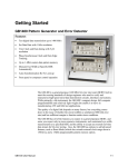
Functional Overview
Analyzer INPUT Section
The controls shown below are used to set up the Analyzer clock and data inputs.
INPUT
DELAY
V-TERM V-THRESH
D-INV
EXT
DATA
DATA
REFERENCE DATA
CLOCK
(1)
CLOCK
(1) (2)
50 Ohm, 2V MAX
50 Ohm, 1.5V MAX
•
DELAY: Press this key to add delay to the DATA or REF DATA inputs to
adjust the clock/data phase relationship. Note that the Auto_Search function
will automatically set data delay to a value which provides the maximum
noise immunity, that is so that the active (falling) edge of the clock falls in
the middle of data bit time slots.
•
V-THRESH: Press this key to set the input decision threshold for the
DATA, CLOCK, and REF DATA inputs. Note that threshold does not apply
when differential operation is selected. Function keys F2 and F3 are OFF
when programming data. Function key F3 is ON when programming REF
DATA.
•
V-TERM: Press this key to select the input terminations for the DATA,
CLOCK, or REF DATA inputs. Available selections are: (GND, -2 V, or
AC). See table below.
•
D-INV: Press this key to select either the data non-inverted (LED off) or
data inverted (LED on) mode.
•
EXT: This is an input for an external data reference signal.
NOTE: Use the F2 and F3 function keys to determine which input will be
affected by the DELAY, V-THRESH, and V-TERM controls as follows:
GB1400 User Manual
F2
F3
Affected Input
off
off
DATA
on
off
off
on
CLOCK
REF DATA
on
on
not allowed
2-23