1
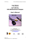
I. GENERAL PRODUCT DESCRIPTION
A. Introduction/Background
Swimming, like any other sport, requires monitoring performance so it can be
analyzed and improved. This tracked data can be used to identify the strengths and
weaknesses of a competitive swimmer. A competent coach will work to improve a
swimmer’s weaknesses, while at the same time using those swimmer’s strengths to
benefit the team. The more a coach knows about his or her swimmers, the better
equipped that coach is to make strategic decisions for team competitions.
B. Problem
With the current advances in sports, however, swimming is not meeting today’s
training standards. It is true that timing equipment for swim competitions is rather
advanced, but swimmers should also be monitored while they train. Current practices of
tracking team data are often clumsy and inefficient. Today’s swim team coaches track
swimmer data using stopwatches while the team works out. This method means that they
can only track one or two swimmers at a time but most teams practice with at least
twenty swimmers in the pool at one time. Once the coach times a swimmer, he must
write the time down if he or she wishes to record the time. This process can draw
attention away from the other swimmers. For the coach who is trying to keep swimmers
focused on sets, look for ways to improve swimmer technique, and instruct swimmers on
the proper way to execute drills, tracking swimmer data with current methods is often
inadequate or overlooked. A swim team coach with a system that could track data for
AquaTrac Functional Specifications
1
them would have a great advantage over swim team coaches using current standards of
tracking. It is for this reason that we are proposing the AquaTrac system.
C. Solution – The AquaTrac System
We have designed a system that will serve as a complete coaching assistant. Our
system will track the performance of swimmers while they train so the coach can focus
on the needs of the swimmers. The system will allow the coach to motivate swimmers
and direct them while they train, then work with data and strategy when practices are
over.
Our team has determined that there are two data points necessary to improving swimmer
performance – times and distances. The AquaTrac system will track times and distances
for all swimmers on a team when they work out. As a bonus, the AquaTrac will also
track heart rates of swimmers while they swim. Through various studies, the AquaTrac
team found that heart rates indicate important information about the effort exerted by a
swimmer while he or she swims. Times and heart rates for each lap will be stored in the
coach’s computer. Data will be organized into graphs and tables so the coach will be
able to use workout data to create competitive strategies and improve swimmer
performance.
AquaTrac Functional Specifications
2
D. General Description of Hardware
The Wrist Device – Worn by Team Swimmers
The AquaTrac system relies on three devices that communicate with each other to
collect data about swimmers. The first unit is a wrist device. Wrist devices are worn by
all of the swimmers during a team workout. The wrist devices collect information about
the swimmers’ workout according to when the swimmers push off of an AquaTrac touch
pad. The touch pads will be mounted on the wall underwater at the starting end of the
pool. Every time a swimmer pushes off of a touch pad, a radio signal emitted indicating
that a lap has been completed. The wrist device monitors the swimmers’ heart rates as
they swim, as well as obtaining times for every lap. The wrist monitor stores all of this
information so that it can send it to the coaching station later in the day, after practice.
The wrist unit also serves as a timepiece. Swimmers can monitor the time as they
swim. More importantly, all the information collected by the wrist device can be
displayed on the screen. If swimmers have a break during their workout they can
manipulate the buttons on the devices to see their own statistics for the last set.
After each practice, the coach will download all of the information from the wrist
units to the main computer using infrared connectivity. The AquaTrac wrist units have to
be within 2 feet of the coaching station.
AquaTrac Functional Specifications
3
The Lane Unit Touch Pads
The AquaTrac Lane units are touch pads as well as radio transmitters. They are
placed at the starting end of each lane in your swimming pool. The touch pads will be
placed such that every time swimmers push off of the starting wall of the pool, he or she
will push off of a touch pad. When a swimmer pushes off of the wall, a radio signal is
sent out to communicate with that swimmer’s wrist device. The radio signal has a short
range underwater. This ensures that only the wrist device on the swimmer who touched
the pad will receive the signal. When the wrist device receives the radio signal it stores
the swimmer’s time for the last lap and the heart rate measured during the lap.
AquaTrac Functional Specifications
4
The Coaching Station – Main Computer
The coaching station is the coach’s information collection tool and planning
center. The coach will be loading information to and from the wrist devices based on
commands entered into the main coaching station. Before practices, the coach will use
AquaTrac software to design a workout routine for that day. Once the routine plan is
completed, the coach will load the information onto the wrist devices by placing the
devices close to the computer and following simple directions provided by the AquaTrac
program. After practices, the coach will load information from the wrist devices onto the
main computer by placing the wrist devices close to the computer and issuing more
commands to the coaching station.
With the information that has been collected from the wrist devices, the coach
will be able to display graphs and tables about a swimmers’ performance.
The coach
can run reports about their times and use heart rate statistics to generalize about the
amount of effort they are putting forth. From the information provided in the AquaTrac
software, the coach will be able to create more competitive strategies and help improve
the times of his or her swimmers.
AquaTrac Functional Specifications
5
E. General Description of Software
The AquaTrac software will serve as the coach’s ultimate tool. Using the
AquaTrac software, the coach will be able to set up teams into organized groups. This
way, if the coach has several different groups on his team, he or she can group them such
that only those swimmers will be called at a time. For instance, if the coach wishes to
organize his team into different age groups, he can work with all of the ten to twelve
year-olds at a time. This is useful for coaches because often they will split up their teams
into different groups so that not everyone is practicing at the same time.
The software also allows the coach to work with every swimmer’s workout data
that has been stored from the wrist devices. Workout data is stored as times and heart
rates for every lap according to the swimmer’s name, or an identification number
associated with that swimmer. The coach will be able to look up any workout that the
swimmer wore a wrist device and view the data in two different formats.
The first way that the coach will be able to observe data is through the use of a
graphical display. The coach will be able to see how swimmers compare to each other in
different sets. The coach will also be able to look at how the swimmer compares to his
own performance on different workouts for the same type of set.
The second way that the coach will be able to observe swimmer data will be to
view the information in a table format. The coach will be able to list fastest times
average times and slowest times for different swimmers and the same workout set.
AquaTrac Functional Specifications
6
From this information, the coach will be able to tell who are the fastest swimmers
on the team, who is putting forth the most effort, and who consistently performs well in
practices. Often, coaches wish to move swimmers up to higher levels of training if they
consistently show that the lower level workouts are too easy. This information will help
the coaches reach those conclusions.
The AquaTrac software will also allow the coach to generate daily work out
routines. Coaches have to plan out how much they want their swimmers to swim on a
daily basis. The AquaTrac software will allow the coach to generate the practices in a
format that is easy for him or her to see. Then, once the workout has been planned, it can
be loaded into the wrist units using infrared communication capabilities.
Finally, the AquaTrac will allow the coach to plan long-term goals for his or her
swimmers. Often, coaches have to plan out long in advance the distances that the
swimmers should swim for each workout in order to prepare them for competitions that
are months away. The AquaTrac will allow the coach to schedule workout plans
according to a yearlong calendar.
AquaTrac Functional Specifications
7
F. Connectivity – General Description
Data will flow between the hardware devices will occur according to the
following diagram…
When a swimmer pushes off of a wall to start a new lap, the touch pad will sense
the touch and send a signal by means of a radio frequency. Since the radio transmission
has only a range of about three feet, the swimmer who pushed off will be the only
swimmer within range of the signal.
The wrist device on that swimmer will receive the signal, indicating that it must
store all of the tracked information for the previous lap.
AquaTrac Functional Specifications
8
Once the practice is over, all of the information stored on the wrist device for that
workout will be uploaded onto the main computer and stored in the main computer’s
database via infrared communication.
AquaTrac Functional Specifications
9
II. PRODUCT HARDWARE
A. Wrist Unit device
1. Functionality
a. Get this from my part of the user’s manual
2. Required Components
a. Battery type: CR 2430
b. Battery life:
~2 years (av. Use, 2 hr/day for 7 day/week)
c. Normal Operating Temperature:
d. Water resistance:
14ºF to 122ºF (-10ºC to 50ºC)
to 160 ft (50m)
e. Wrist strap:
polyurethane
f. RF receiver:
RFD27994 from www.rfdigital.com (433MHz Raw Serial
Data Wireless RF Transceiver Module)*
g. Backcover of unit and wrist buckle: Stainless steel in accordance with
EU Directive 94/27/EU and its amendments 1999/C 205/05 on the release
of nickel from products intended to come into direct and prolonged
contact with the skin.
h. Accuracy:
better than ±0.5 sec/ day for timekeeping, better than ± 1%
or ± 1bpm
i. Polar S610i is a Class 1 Laser Product.
3. Measurements
a. Wrist unit strap:
L: 3.25 inches (top strap), 5 inches (bottom strap),
W: 1/16 inch
b. Wrist unit buckle:
.75 inches
AquaTrac Functional Specifications 10
c. Wrist unit body:
L: 1.5 inches, W: 1/3 inch
AquaTrac Functional Specifications 11
B. Lane Unit / Touch Pad
1. Components Necessary
The following components are suggested materials for construction of the touch
pad unit.
- 1 50 ft (15.25 m) coated power cable with an outlet plug attached to the
end.
- 2 Copper Sheeting or Copper grid (55 inches (1.397 meters) wide, 18
inches (45.7 cm) high, .039 inches (1 millimeter) thick)
- 12 Rubber Spacers (.039 inches (1 mm) X .039 inches (1 mm) X .039 inches
(1 mm))
- Durable Plastic Molding Material
- 12 Gauge Coated Copper Wiring
- Coated Antenna Wiring
- 1 Processor Box – A hard-wired circuit, connected to the Copper sheets, the
Power supply, and the Antenna that will control the radio frequency (20 mHz at a
range of 121.92 cm(4ft.)) output based on a push on the touch pad.
AquaTrac Functional Specifications 12
2. Appearance and Dimensions of the Touch Pad Front View
The front face of the touch pad should be 60 inches wide and 22 inches long. The
pad should be colored black and white, with an upside-down “T” showing on the front.
As an example of appearance, refer to Figure II.B.1.
Figure II.B.1
AquaTrac Functional Specifications 13
3. Appearance and Dimensions of the Touch Pad Side View
The back of the touch pad should extend 5 inches out at a right angle from the top
of the touch pad. It should then extend 3.6 inches at another right angle. This is so the
touch pad can hang snuggly on the gutter of a training pool. Refer to Figure II.B.2 for
shape and dimensions.
Figure II.B.2
AquaTrac Functional Specifications 14
4. Touch Pad Assembly
The following is a suggested assemblage for constructing the Touch Pad Lane
unit. Refer to Figure II.B.3 for the following sections.
Figure II.B.3
A. The back of the touch pad should be constructed from heavy duty plastic. It
should conform to the length and height dimensions set forth in Figure I.B.1.
B. Copper Sheeting / Grid – 12 rubber spacers should be evenly distributed and
molded to the front of Panel B such that when Panel B and C are placed next to
each other, they are separated by a space of 1 millimeter.
C. Copper Sheeting / Grid – 12-gauge wire should be soldered to one end of each
copper sheet and extended into the Processor Box on Panel D.
D. This panel should be constructed of silicon and adhere to the same dimensions as
the copper sheeting/grid. The Processor Box should be molded onto Panel D,
AquaTrac Functional Specifications 15
with antennae wire, a power cable, and 12-gauge coated copper wiring feeding
into it. The antenna wiring should be woven and mounted to Panel D such that for
every 2 square inches of Panel, there is wiring mounted to the Panel (for an
illustration of how the antenna should be woven onto the panel refer to Figure
II.B.4.
Figure II.B.4
E. The front panel should be constructed of heavy duty plastic and display the image
set forth by Figure I.B.1.
Once all of the Panels have been constructed and assembled according to the above
specifications and Figure II.B.3, Panel E should be molded to Panel A such that Panels B
through D are enclosed within. The entire assembly should be sealed such that no water
can enter at any point.
AquaTrac Functional Specifications 16
5. Placement of Power Supply Cord
!!!! Note: The Power Cord must be sealed so as mot to let any water enter
any point of the device. Water leaks could result in serious injury by way of electric
shock.
Figure II.B.5
AquaTrac Functional Specifications 17
6. Logical Connectivity of Wiring, Functionality of Circuitry
The Processor box should be assembled such that it integrates all of the connected
wires into an electrical circuit that performs the following functionality. (Refer to Figure
II.B.6 for connectivity.)
Figure II.B.6
The Power Supply cable, the copper sheets, and the antenna wiring should be
connected as an open circuit. The circuit is open where the two copper sheets are placed
AquaTrac Functional Specifications 18
apart from one another. Once the touch pad is pushed, the copper sheets should touch
each other, closing the circuit. When the circuit is closed, a steady Radio Frequency of
20 mHz should be transmitted from the antenna at a range of 121.92 cm (4ft.). The
antenna must emit a signal strong enough to transmit at the given range through the front
panel of the touch pad and transmit through water that has a hardness level of 200 ppm, a
chlorine level of 1 ppm, and an alkalinity of 120 ppm. Standard pool water has a
hardness level in the range of 100-300 ppm, a chlorine level in the range of 1-2 ppm, and
an alkalinity measure in the range of 100-140 ppm, so the specifications designated above
will suffice for accuracy. The antenna should stop transmitting once the copper sheets
are no longer touching, as the elasticity of the rubber spacers will push them apart once
the swimmer releases.
Standard Pool Water Concentration Levels Taken from:
http://www.nature2.com.au/installation.cfm
AquaTrac Functional Specifications 19
C. System Requirements for Computer Workstation
1. Minimum requirements
a. Infrared port
i. External- USB-IR Infrared Transceiver USB to IRDA^ from
www.trianglecables.com
b. Memory requirements- 128 Mb RAM
c. CPU requirements- 500 MHz Pentium 3
d. OS requirements- Windows 98
e. HD requirements- 800 Mb free space
2. Recommended
a. Memory- 256 Mb RAM or higher
b. CPU- 750 MHz Pentium 4 or higher
c. OS- Windows XP
d. HD- 1 GB or higher free space
^Description
Supports SIR and FIR.
Obtains power from USB port.
Uses Standard IrDA transceivers.
IrDA data rates from 2.4Kbps to 4 Mbps.
Active LED indicator.
Full compliance to IrDA 1.3 and USB 1.1 specifications.
4Kbyte FIFO buffer memory.
AquaTrac Functional Specifications 20
Supports SIR and FIR Win98/98SE/ME/2000 NDIS USB Drivers.
Supports SIR and FIR Low-Power CMOS design.
*Description
Transmits raw serial data to RF Digital raw data RF
receivers, also receives serial data transmitted by other RF Digital
raw data RF transmitters. Has 7 inch wire wip antennas for maximum range.
Antenna can be cut by user to reduce range for applications that require less range.
Typical maximum range is 150 feet.
AquaTrac Functional Specifications 21
III. PRODUCT SOFTWARE
A. Operating Platform / System Requirements
The analysis/reporting application and the device driver programs must be developed to
run on the following operating platform and system requirements:
• Microsoft Windows 2000 or Microsoft Windows XP Server Edition
• An Intel Pentium III with 500MHz or higher
• A minimum of 512MB of RAM
B. Data Storage / Input
1. Functionality
1. Initiating Data Transfer from the Wrist Device
The device driver programs developed should be able to manage the
infrared device and the IrDA port of the coach’s workstation. Upon
a request from the GUI to retrieve the data, the device driver
programs should interact with the infrared device to perform a
wireless connection with the wrist device. Once the connection is
established, the programs should initiate the data transfer. The
maximum data transfer rate to be expected is 115kbps, in both
directions.
2. Decoding the Received Data
The device driver programs must be able to interpret and decode
infrared signals into binary formats. The binary data should then be
converted into appropriate ASCII codes.
3. Extracting the Received Data
AquaTrac Functional Specifications 22
The incoming data from the wrist device contains the fields below.
The fields are in order as listed.
• Wrist Device Sequence Number
• Wrist ID
• Set Date/Time
• Set Type
• Set Interval
• Elapsed Time
• Average Heart Beats/Elapsed Time
The “tab” ASCII character should be used to separate all of the
fields except for “Average Heart Beats/Elapsed Time”. The
“return” ASCII character should separate each set (record).
4. Validating Received Set Data
Once the individual data fields have been properly extracted, they should be
validated. Each field should be validated based on its predefined data type. The set
records should be checked for duplication. Duplicated set records should be reported to
the analysis/reporting application. The application should then inform the user about the
error. In addition, the set dates/times should be compared with the existing data for the
swimmer on the database. This validation will justify that the swimmer has not uploaded
data for a second time in one day. If the validation fails, the error should be passed on to
the analysis/reporting application, where it can be reported to the user.
5. Saving Set Records to Database
AquaTrac Functional Specifications 23
After the set records are properly validated, they can be inserted to
the appropriate tables on the local database.
Required Components
3. Device Driver Programs
The device driver programs should be developed using ANSI C
language. Assembly language can be used if necessary. Appropriate
compilers should be used such that the programs can be executed on
the platform determined by part III.A.
4. Database Server
Microsoft SQL Server 2000 Standard Edition should be used as the
database server. The database size should be 2GB.
5. Database Design
The diagrams below depict how the database should be designed.
AquaTrac Functional Specifications 24
Database Diagram with Primary (PK)/Foreign Key Relationships
• swimmer.team_id (FK) references team.team_id (PK)
• set.swimmer_id (FK) references swimmer.swimmer_id (PK)
• set.set_type_id (FK) references set_type.set_type_id (PK)
• set_detail.set_id (FK) references set.set_id (PK)
Team Table
AquaTrac Functional Specifications 25
Swimmer Table
Set Table
Set Type Table
AquaTrac Functional Specifications 26
Set Detail Table
6. Database Application
The database application used to insert set records from the upload
text file to the database should be written in Microsoft Visual C++.
When inserting set records, the application should maintain the
integrity of the database by conforming to the rules mentioned
above.
7. Infrared Device
The infrared device ACT-IR210L (see pictures below) from
ACTISYS Corporation (www.actisys.com) must be used for the
coach’s computer. The device driver programs should be developed
for the ACT-IR210L. Please refer the company’s web site for detail
specifications of the ACT-IR210L.
AquaTrac Functional Specifications 27
Infrared Device ACT-IR210L from ACTISYS Corporation
AquaTrac Functional Specifications 28
C. Formatting Specifications for the Application Software
This section represents the specifications for the AquaTrac application program. It will
constitute the basis for programming this segment of the AquaTrac system.
Format descriptors will sometimes precede the text descriptions of the input and display
fields in this section.
“A” meaning “alphanumeric” is restricted to the set of all printable characters in the
ASCII range from 0 to 127. When followed by a number, this descriptor indicates the
number of characters allowed in that field. For example, A4 means 4 alphanumeric
characters.
“I” meaning “integer” is restricted to the set of all non-negative integers. When followed
by a number, this descriptor indicates the number of digits allowed in that field. For
example, I4 means an integer of no more than 4 digits.
“F” meaning “floating-point” is restricted to the set of all non-negative floating-point
numbers. When followed by a number, this descriptor indicates the number of digits
allowed before and after the decimal point in that field. For example, F4.2 means a
floating-point number of 4 digits before the decimal place and 2 digits after the decimal
place.
“L” meaning “logical” is restricted to the a value of 0 or 1 (“yes” or “no)
AquaTrac Functional Specifications 29
Terminology
“Swimmer” – A swimmer on a Team
“Swimmer Name” – The name of a Swimmer
“Swimmer ID” – The unique identifier assigned to each Swimmer
“DOB” – The date of birth of a Swimmer
“Height” – The height of a Swimmer
“Weight” – The weight in pounds of a Swimmer
“Team” – A swim team existing in the system
“Teams” – The set of Team Names
“Team Name” – The name of the Team
“Team ID” – The unique identifier assigned to each Team
“Set” – A particular swim set for a Swimmer
“Set Type” – The stroke type of for a Set
“Set Date” – The date a particular Set was recorded
“Set Interval” – The distance interval at which Interval Times and Heart Rate are
recorded.
“Set Distance” – The total distance for a particular Set
“Interval Time” – The time recorded at each Set Interval
“Set Time” – The total elapsed time for a Set
“Heart Rate” – The total number of heartbeats recorded at each Set Interval
AquaTrac Functional Specifications 30
“Data” – All of the recorded/historical data for a Team
Common Field Formats
Certain formats appearing in multiple segments of this section are given here:
§
Swimmer First Names should be A25
§
Swimmer Last Names should be A25
§
Swimmer IDs should be I and fixed at 6 digits
§
Team Names should be A50
§
Team IDs should be I and fixed at 6 digits.
§
DOBs should be formatted as DD/MM/YY
§
Height should be formatted as FEET’ INCHES”
§
Weight should be I3
§
Set Type is A and can only be “freestyle”, “backstroke”, “breaststroke”,
“butterfly”, or “mixed”
§
Set Date should be formatted as DD/MM/YY
§
Set interval is I4, can only be a multiple of 50, and can be no greater than
5,000.
§
Interval time should be formatted as HOUR.MINUTES.SECONDS
§
All time fields should be formatted as HOUR.MINUTES.SECONDS
§
Heart Rate should be I3
General Notes
A global Team ID should be used as the identifying key for access to Team data. For
purposes of this specification, this global Team ID will be called Global Team ID.
AquaTrac Functional Specifications 31
D. Application Functions
Application Menu
The application menu should provide all the menu items necessary to access the various
functions of the application program.
Open Team
Description: To set the Global Team ID for data access.
Required input field for this function:
§
Teams
If the Team Name is valid, the Global Team ID should be set to the Team ID. The Global
Team ID will be used to:
§
access Swimmer data for all relevant functions
§
set an output field for all relevant functions
New Team
Description: To add a new Team to the system
Required input field for this function:
§
Team Name
The new Team will be added to the system at the database level.
AquaTrac Functional Specifications 32
Edit Team
Description: To edit the Team Name currently opened.
Required input field for this function:
§
Team Name
The new Team Name will be changed in the system at the database level.
Remove Team(s)
Description: To set a Team’s account to an inactive status.
Required input field for this function:
§
Team Name
§
L: prompt user to proceed with removal
If the prompt returns yes, all changes to the Team’s account will be done at the database
level.
All Swimmer accounts for the Team will also be set to an inactive status.
Close Team
Description: To reset the Global Team ID to non-accessible value
Required input field for this function:
§
L: prompt user to proceed with close
If the prompt returns “Yes”, the Global Team ID will be reset to a non-accessible value.
AquaTrac Functional Specifications 33
Exit
Description: To exit the program
There are no requirements for this function other than to exit the application.
Edit
Description: To provide the standard functions necessary for editing input text.
These standard functions should include “undo”, “redo”, “cut”, “copy” and “paste”
Table Builder
Description: To obtain the values necessary to build the Table Builder Report (See a
description of this report in the Reports section).
Terminology for this function:
“Start Date” – Date at which to start search for Swimmer data
“End Date” – Date at which to end search for Swimmer data
Required input fields for this function:
§
3 instances of Swimmer Name
§
Set Distance
§
Set Type
§
Start Date
§
End Date
AquaTrac Functional Specifications 34
Each value of Swimmer Name should be unique (A particular Swimmer should not be
selected more than once).
At least one Swimmer Name must be selected.
The function should find only those Sets that correspond to the values for Set Distance
and Set Type, and are in the range specified by Start Date and End Date.
Graph Builder
Description: To obtain the values necessary to build the Graph Builder Report (See a
description of this report in the Reports section).
Terminology for this function:
“Start Date” – Date at which to start search for Swimmer data
“End Date” – Date at which to end search for Swimmer data
“Graph Type” – The type of graph to be displayed in the Graph Builder Report
“Set Number” – The particular Set to be graphed in the Graph Builder Report
Required input fields for this function:
§
3 instances of Swimmer Name
§
Set Distance
§
Set Type
§
Start Date
§
End Date
AquaTrac Functional Specifications 35
§
A: Graph Type – can only be “Averages”, “Single Race (Individual)”, or
“Single Race (Multiple Individual)”
§
A: Set Number – should be formatted as SET:NUMBER - DATE
Each value of Swimmer Name should be unique (A particular Swimmer should not be
selected more than once).
At least one Swimmer Name must be selected.
The function should find only those Sets that correspond to the values for Set Distance
and Set Type, and are in the range specified by Start Date and End Date.
From the Sets found for each Swimmer, the user should select a Set Number to graph in
the Graph Builder Report.
Load Swimmer Data
Description: To initiate the data transfer between the wrist monitor and the database.
Required input fields for this function:
§
L: prompt user to proceed with data transfer
If the prompt returns “Yes”, the data transfer process will begin.
Add Swimmer(s)
Description: To add a new Swimmer to a Team
Required input fields for this function:
§
Swimmer Name
AquaTrac Functional Specifications 36
§
DOB
§
Height
§
Weight
The new Swimmer will be added to the Team at the database level.
Remove Swimmer(s)
Description: To set a Swimmer’s account to an inactive status.
Required input field for this function:
§
Swimmer Name
§
L; prompt to proceed with removal
If the prompt returns “Yes”, all changes to the Swimmer’s account will be done at the
database level.
Schedule
Description: To provide a “notepad” for entering text to be associated with a particular
calendar day.
Terminology for this function:
“Date” – a calendar day
“Notes” – the text associated with the Date
Required input/output fields for this function:
§
Date (input only)
AquaTrac Functional Specifications 37
§
A500: Notes (input and output)
Notes are entered, modified and viewed in the same field.
Notes are saved for the Date selected upon exiting the function.
Setup Practice
Description: To store a collection of Sets for a particular workout routine.
Terminology for this function:
“Date” – a calendar day
“Workout” – A set of Sets to be completed during the workout routine
Required input fields for thus function:
§
Date
§
Set Distance
§
Set Type
§
L: Prompt to add the set to the workout routine
If the prompt returns “Yes”, a Set will be added to the Workout for the Date selected.
The Set will specify the Set Distance and Set Type.
Multiple Sets can be added consecutively to the Workout.
Workouts are saved upon exiting the function.
View User Manual
Description: To display the product user manual.
AquaTrac Functional Specifications 38
The user manual will open in Portable Document Format for viewing upon execution of
this function.
AquaTrac Functional Specifications 39
E. Application Reports
Table Builder Report
Description: The output generated from the Table Builder function.
Terminology for this report:
“Average Time ” – The average Set Time for the Sets retrieved
“Best Time” – The shortest Set Time for the Sets retrieved
“Worst Time” – The longest Set Time for the Sets retrieved
Required output fields for this report:
§
3 instances of the Swimmer Name
§
Set Distance
§
Set Type
§
Average Time
§
Best Time
§
Worst Time
§
Start Date
§
End Date
Set Distance, Set Type, Start Date and End Date should be headers for this report.
Average Time, Best Time and Worst Time should be displayed for each Swimmer.
An example of the table format is shown below:
AquaTrac Functional Specifications 40
Graph Builder Report
Description: The output generated from the Graph Builder Function.
Terminology for this report:
“X-Axis” – the x-axis of the graph; the axis for which Interval Distance is plotted
“Y-Axis” – the y-axis of the graph; the axis for which Interval Time is plotted
“Distance/Time Point” – the intersection of Interval Time and Set Interval.
Averages Report
Description: To graph the Average Set Times for each Swimmer selected
Required fields for this report:
§
3 instances of Swimmer Name
§
Set Distance
§
Set Type
§
A: Set Number – should be formatted as SET:NUMBER - DATE
§
Average Time
§
Start Date
§
End Date
§
Interval Distance
AquaTrac Functional Specifications 41
§
Interval Time
§
Heart Rate
Swimmer Name, Set Distance, Set Type, Set Number, Start Date and End Date should be
headers for this report.
The X-Axis should be plotted as Set Intervals up to the Set Distance.
The Y-Axis should be plotted in a range from 0 to 60 seconds.
Interval Time for Average Time should be plotted at each Set Interval.
Heart Rate should be displayed above each Time/Distance Point.
An example of this graph is shown below:
AquaTrac Functional Specifications 42
Single Race Individual
Description: To graph multiple Sets for a Swimmer
Required fields for this report:
§
Swimmer Name
§
Set Distance
§
Set Type
§
A: Set Number – should be formatted as SET:NUMBER - DATE
§
Start Date
§
End Date
§
Interval Distance
§
Interval Time
§
Heart Rate
Swimmer Name, Set Distance, Set Type, Set Number, Start Date and End Date should be
headers for this report.
The X-Axis should be plotted as Set Intervals up to the Set Distance.
The Y-Axis should be plotted in a range from 0 to 60 seconds.
Interval Time for the Set Times should be plotted at each Set Interval.
Heart Rate should be displayed above each Time/Distance Point.
An example of this graph is shown below:
AquaTrac Functional Specifications 43
Single Race (Multiple Swimmer)
Description: To graph multiple Sets for multiple Swimmer.
Required fields for this report:
§
3 instances of Swimmer Name
§
Set Distance
§
Set Type
§
A: Set Number – should be formatted as SET:NUMBER - DATE
§
Start Date
§
End Date
§
Interval Distance
§
Interval Time
§
Heart Rate
AquaTrac Functional Specifications 44
Swimmer Name, Set Distance, Set Type, Set Number, Start Date and End Date should be
headers for this report.
The X-Axis should be plotted as Set Intervals up to the Set Distance.
The Y-Axis should be plotted in a range from 0 to 60 seconds.
Interval Time for the Set Times the should be plotted at each Set Interval.
Heart Rate should be displayed above each Time/Distance Point.
An example of this graph is shown below:
AquaTrac Functional Specifications 45
IV. WRIST DEVICE SOFTWARE
A. Operating Platform/System Requirements
The software application and the device driver programs must be
developed to run on the same microprocessor as the s610i (see below) from
Polar USA. Please refer to the company’s web site (www.polarusa.com) for
detail specifications for the s610i.
S610i from Polar USA
B. Interfacing with the Coaching Station
1. Functionality
1. Accepting Request for Data Transfer
Upon receiving a request for data transfer from the coach
computer, the device programs should interact with the infrared module of
the wrist device to send a signal, indicating acceptance.
2. Preparing Set Data for Transfer
Once the infrared link is established, the device programs should
interface with the storage device and begin retrieving the set data. The set
data should be placed temporarily in memory so it can be accessed and
translated into infrared wave forms.
AquaTrac Functional Specifications 46
3. Transferring Set Data
The device driver programs should access the set data (binary
format) in memory and convert it into appropriate infrared signals. The
infrared device should then be triggered to send the signals to the coach
computer. The set data to be sent should include the following:
• Wrist Device Sequence Number
• Wrist ID
• Set Date/Time
• Set Type
• Set Interval
• Elapsed Time
• Average Heart Beats/Elapsed Time
4. Detecting and Correcting Transmission Error
During data transfer, the device driver programs should be able to
detect and correct synchronization errors.
2. Required Components
1. Device Driver Programs
The device driver programs should be developed using ANSI C
language. Also, assembly language can be used when necessary.
Appropriate compilers should be used so that the programs can be
executed properly on the platform mentioned on part IVA.
2. Infrared Device
AquaTrac Functional Specifications 47
The device driver programs should be developed for the infrared
device existed on the S610i from Polar USA. Please refer the company’s
web site (www.polarusa.com) for detail specifications of the infrared
device.
C. Interfacing with the Touch Pad
1. Functionality
1. Required Processes
While the AquaTrac wrist device is in “workout” mode, the
processor must continually increment time in units of minutes, seconds,
hundredths of a second, and increment heartbeats according to sensation
signals received via the heart monitor sensor.
2. Receiving Radio Signal from Touch Pad
Upon receiving a radio signal from the touch pad, the wrist device
processor must calculate heart rate by dividing the number of heartbeats
by the current elapsed time. It must then store both time and heart rate
according to the data fields, “Elapsed Time” and “Average Heart Beats/
Elapsed Time”, defined in the Transferring Set Data section on the
previous page. The processor then must reset both counts of time and
heart beat.
AquaTrac Functional Specifications 48