1
ESRF
ISG
INSTRUMENT SUPPORT GROUP
Control Electronics
MUSST
RUN
TRIG
in
MUSST
out A
Multipurpose Unit for
Synchronisation, Sequencing and Triggering
out B
card
1
2
User Manual
card
3
4
card
5
6
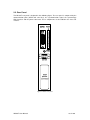
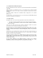
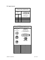
DESCRIPTION
MUSST is an NIM module that produces trigger patterns synchronised with external events. A
trigger pattern is a sequence of trigger output signals that can be adapted to the specific
needs of a particular experiment and be used to synchronise the different beamline
components involved. In addition, the built-in data storage capability makes possible to use
the module as a data acquisition unit.
The detection of events is achieved by hardware comparators that guarantee the proper
synchronisation of trigger patterns and minimum delays in the generation of output signals.
Events can be chained in order to produce specific trigger sequences. A programmable
sequencer is in charge of executing application specific programs that can be written by the
user in a high-level language and transferred to MUSST through one of the available
communication ports: GPIB or serial line.
The functionality of this module covers a wide range of the requirements found at the ESRF
beamlines in what concerns synchronisation and triggering. Existing applications that could
benefit from the features of the module are among others: continuous scans at constant or
variable step, 2D mapping, synchronous operation of shutters or fast scans with special
detectors like CCD sensors in kinetics mode.
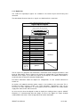
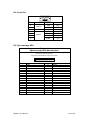
Date
31/05/2006
28/05/2007
15/07/2009
Version
0.2
1.0
1.1
MUSST User Manual
Comments
Current draft version.
First complete version.
Modified analogue input cabling, included new daughter card.
2 of 100
CONTENTS
MANUAL ORGANIZATION
5
1. FUNCTIONAL DESCRIPTION
6
1.1. SIGNALS AND FUNCTIONAL BLOCKS
1.1.1. INPUT SIGNALS
1.1.2. BIT PATTERN UNIT
1.1.3. TRIGGER SIGNALS
1.1.4. SEQUENCER
1.1.5. COMPUTER CONTROL
1.1.6. SPECTROSCOPY ADC INTERFACE
7
7
8
8
8
8
8
2. HARDWARE DESCRIPTION
9
2.1. FRONT PANEL
2.1.1. RUN
2.1.2. TRIG IN, TRIG OUT A, TRIG OUT B
2.1.3. DIGITAL I/OS
2.1.4. INPUT CHANNELS
2.2. REAR PANEL
2.2.1. GPIB
2.2.2. SERIAL LINE PORTS
2.2.3. TRIG
2.2.4. ADC
2.2.5. NIM POWER SUPPLY
9
10
10
12
13
15
16
16
17
17
18
3. OPERATION INSTRUCTIONS
19
3.1. INSTALLATION AND CONFIGURATION
3.1.1. COMMUNICATION: GPIB AND SERIAL PORTS
3.1.2. INPUT CHANNELS
3.1.3. DIGITAL I/OS
3.1.4. TRIGGER SIGNALS
3.1.5. SEQUENCER PROGRAM AND DATA STORAGE
3.1.6. SPECTROSCOPY ADC
3.2. USAGE TIPS
19
20
20
21
21
22
22
23
4. COMMAND SET
24
4.1. COMMAND REFERENCE
25
MUSST User Manual
3 of 100
APPENDIX A. MUSST COMMAND QUICK REFERENCE
80
APPENDIX B. COMMUNICATION PROTOCOL
82
B.1. COMMUNICATION PORT
B.1.1. SERIAL LINE PORTS
B.1.2. GPIB INTERFACE
B.2. SYNTAX CONVENTIONS
B.2.1. COMMANDS AND REQUESTS
B.2.2. ADDRESSING
B.3. COMMON COMMANDS
B.4. TERMINAL MODE
B.5. EXAMPLES
B.6. BINARY TRANSFER
B.6.1. SERIAL PORT BINARY BLOCKS
B.6.2. GPIB BINARY BLOCKS
82
82
83
84
84
85
86
87
88
89
90
90
APPENDIX C. ELECTRICAL DESCRIPTION
91
C.1. DIGITAL I/OS
C.2. INPUT CHANNELS
C.3. REAR PANEL TRIG
C.4. SPECTROSCOPY ADC AND ICB
91
91
92
92
APPENDIX D. CABLING SUMMARY
94
D.1. TRIGGER SIGNALS AND AUXILIAR CHANNEL INPUTS
D.2. DIGITAL I/OS
D.3. INPUT CHANNELS
D.4. SERIAL LINE
D.5. SPECTROSCOPY ADC
94
94
95
98
98
APPENDIX E. ACCESSORIES
MUSST User Manual
100
4 of 100
MANUAL ORGANIZATION
Section 1 gives a brief overview of the MUSST functional aspects as well as its main
functional blocks. The description is made in general terms and specific technical details are
minimised.
Section 2 describes the MUSST hardware. The connectors and signals functions of both front
and rear panels are detailed.
Section 3 is dedicated to the MUSST deployment in a real world setup.
Section 4 covers the available commands to communicate with MUSST.
MUSST User Manual
5 of 100
1. FUNCTIONAL DESCRIPTION
One of the main goals in the development of MUSST was to produce a module that is
independent of the particular driving electronics (motor controllers, piezo drives or sensors,
etc) and the data acquisition system (counting chains, CCD cameras, detector electronics,
ADC’s, etc). In this way a large number of experiments that use very diverse hardware can be
synchronised in a homogeneous way with minimum differences in software. A dedicated and
flexible enough module for triggering and synchronisation presents in addition the advantage
that can be used both with the existing control hardware and with new commercial or in-house
developed modules in the future.
A MUSST module includes 6 signal input channels. These channels admit either incremental
or sampled absolute signal values. In this way the module can operate with the diversity of
signals used at the beamlines like positions from stepper motors, incremental encoders,
frequency inputs, analogue sensors, absolute encoders, piezoelectric actuators, etc. The use
of internal interchangeable input modules (daughter cards) allows dealing with the electrical
particularities of each type of signal.
In addition to the signal input channels, MUSST includes a 32-bit timer, a module with 16 TTL
I/O signals that is used to read and generate bit patterns and external trigger inputs and
outputs.
A primary event happens either when an input signal reaches a target value, when an input
bit pattern matches a predefined value, after a certain programmed time or when one of the
external trigger input signals is received. Several primary event conditions can be combined
to generate more complex events. At each event the unit can be programmed to take one or
several actions. Possible actions are:
- Generation of trigger output signals.
- Update of the output signals of the TTL I/O module
- Storage of the input values and internal timers in RAM
Several units can be cascaded to produce more complex trigger sequences or operated
synchronously in parallel to increase the number of effective input channels.
The next sub-sections give a general description of the main components of a MUSST
module.
MUSST User Manual
6 of 100
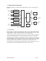
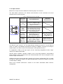
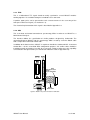
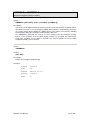
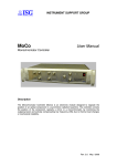
1.1. Signals and functional blocks
The figure below depicts a simplified functional block diagram and the associated signals of
MUSST.
Input module 0
Channel 0
Channel 1
µController
Input module 1
Channel 2
Channel 3
Input module 2
Event
Generator
Channel 4
Sequencer
GP-IB
interface
GP-IB
Bus
Channel 5
16
Bit Pattern Unit
ADC
interface
Spectroscopy
ADC
TRIG in
TRIG out
2
Memory
Figure 1: MUSST simplified block diagram
1.1.1. Input signals
MUSST includes three groups of two signal input channels. It is possible to install up to three
internal daughter cards (one per group) adapted to a specific type of signal. The internal logic
supports two types of signals: counting (incremental) and sampled (absolute).
Incremental signals (motor position, incremental encoders, frequency outputs) are integrated
in time by using up/down counters. The maximum input frequency in this case is 25 MHz.
Sampled signals (like analogue values or absolute encoders) are sampled at a fixed rate and
can be optionally processed by a digital IIR filter. The maximum sampling rate is dependent
on the bit resolution. 16-bit sampling can be achieved up to 3 MHz. In practice the actual
sampling rate depends on the design of each particular input module (daughter card).
The input signals are internally represented in 32 bit words. Those channels that are not used
for external signals can be reconfigured internally as timers or event counters.
MUSST User Manual
7 of 100
1.1.2. Bit pattern unit
This unit handles 16 TTL signals that are accessible from a front panel connector and can be
independently configured as input or output lines.
Bit patterns can be extracted from this set of signals by using mask registers and decoded to
generate trigger conditions. All 16 digital signals are sampled at each programmed event and
can be optionally stored in memory. Input lines can be configured to latch fast pulses.
Output bit patterns can be set by software or automatically generated by the sequencer at
each event. In this way it is possible to produce level-active signals like detector gates or
shutter control lines.
1.1.3. Trigger signals
MUSST can be programmed to generate TTL output pulses at selected events. These pulses
are accessible through two front-panel connectors.
An external TTL trigger signal can be used as an input to synchronise the module with
external devices. A front panel connector is available for this use.
It is also possible to synchronise several MUSST modules between them by means of a
dedicated signal accessible at the rear panel.
1.1.4. Sequencer
The combination of trigger conditions and events to produce more complicated trigger
sequences is accomplished by a logic unit that is able to decode and execute a reduced set
of microcoded instructions. Microcode is stored in a memory block and instructions are
fetched and executed by the sequencer.
In addition to microcode, the memory can be also used to store the values of the input
channels at selected events along with the internal time and the digital value of the bit pattern
unit.
The sequencer runs at 50 MHz and most of the microcoded instructions are executed in one
to three clock cycles (20 to 60 ns).
1.1.5. Computer control
All the different internal units of MUSST are initialised and operated by a microcontroller that
also manages a standard GPIB interface for communication purposes.
The firmware running in the microcontroller implements a high-level command set that allows
and simplifies the control of the module by an external computer. The microcontroller also
compiles on-the-fly the sequencing program into microcoded instructions to be executed by
the sequencer.
1.1.6. Spectroscopy ADC interface
MUSST can be used as a Multi-Channel Analyzer when associated with a commercial
spectroscopy ADC. The ADC data transfer is done by means of a Canberra® based interface.
In addition, MUSST can deal with the Canberra® Instrument Control Bus for configuration
purposes.
MUSST User Manual
8 of 100
2. HARDWARE DESCRIPTION
The MUSST hardware is composed by the front panel, the rear panel, the internal boards and
the optional daughter cards. The following sub-sections detail each one of these components.
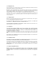
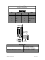
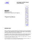
2.1. Front Panel
The MUSST front panel is depicted in the figure below. The front panel gives access to the
input channels, the trigger signals, the digital I/Os and the visual indicators. The functionality
of these components is described in the next paragraphs.
RUN
TRIG
in
Bit pattern
digital I/Os
Trigger signals
out A
out B
card
Input channels
1
2
card
3
4
card
5
6
Figure 2: MUSST Front Panel
MUSST User Manual
9 of 100
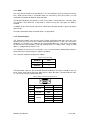
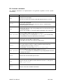
2.1.1. RUN
The front panel yellow RUN LED provides a visual indication of the states of the module in
what concerns the sequencer program according to the following table.
Table 1: MUSST main states
RUN LED
off
on
blinking
STATE
IDLE
NOPROG
PROG
ERROR
RUN
STOP
BREAK
STATE DESCRIPTION
No sequencer program running
Sequencer program running
Sequencer program stopped
See the ?STATE request in Section 4.1 for a detailed description of the complete set of states
of the module.
2.1.2. TRIG in, TRIG out A, TRIG out B
The front panel trigger signals are available in 3 Lemo® 00-series connectors. The function
and electrical characteristics of these signals are described in the table below.
Table 2: MUSST trigger signals
Connector/
Indicator
TRIG in
TRIG out A
TRIG out B
signal
activity
red LEDs
MUSST User Manual
Function
Input trigger signal:
allows synchronisation of
MUSST with external devices
or acts as an external gate for
the MCA application
Output trigger signal A:
100ns positive pulse
that can be generated
at an event occurrence
Output trigger signal B:
its logic level can be toggled
at each event occurrence or
set to a desired level
(by software or by the
sequencer)
For merely visual control, the
activity of these signals can be
observed by the blinking of the
correspondent LED (one for
the input and another one for
the two output trigger signals).
Electrical Characteristics
LOW level: 0,8V max
HIGH level: 2,0V min
LOW level: 0,44V max (no load)
HIGH level: 3,76V min (no load)
Output impedance: 50Ω
LOW level: 0,44V max (no load)
HIGH level: 3,76V min (no load)
Output impedance: 50Ω
10 of 100
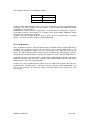
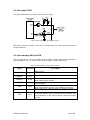
The figure below illustrates how the output trigger signals can behave when a sequence of
events is detected by the module.
Figure 3: MUSST front panel trigger outputs
This example is valid only if both signals have been selected to take part of the list of actions
the module must carry out at an event occurrence. For more details about the list of actions,
see Section Error! Reference source not found..
MUSST User Manual
11 of 100
2.1.3. Digital I/Os
The 16-bit TTL input/output signals are available in the female 25-pin Sub D front panel
connector.
The table below illustrates how these signals are distributed in the connector.
Table 3: MUSST Digital Inputs and Outputs
Digital Inputs/Outputs
Front panel
25-pin female sub-D connector
Pin
1
2
3
4
5
6
7
8
9
10
11
12
13
15
18
21
24, 25
14, 16,
17, 19,
20, 22
and 23
Signal
I/O 0
I/O 1
I/O 2
I/O 3
I/O 4
I/O 5
I/O 6
I/O 7
I/O 8
I/O 9
I/O 10
I/O 11
I/O 12
I/O 13
I/O 14
I/O 15
+5V (200mA max.)
Default Direction
INPUT
OUTPUT
ground
The 16 signals are grouped in four 4-bit blocks. Each block can be configured to work as 4-bit
inputs or 4-bit outputs signals. However, by default, this configuration is not allowed and the
direction of the signals is pre-defined (8 inputs and 8 outputs). A hardware intervention is
needed in order to change the direction configuration.
For further information about the digital I/Os configuration, see the IOCFG command in
Section 4.1.
An auxiliar +5V (200mA maximum) power supply is also available in this connector. This is
intended to power interface circuits (e.g., level translators, optocouplers) that can be
necessary in certain applications. A self-resetable internal fuse protects this auxiliar power
supply from short-circuits and overcurrent.
An accessory has been developed in order to simplify the cabling of these signals. MUSST
Extender is a interconnection box that allows to access the digital I/O signals through
standard BNC connectors. Refer to Appendix E for further information.
MUSST User Manual
12 of 100
2.1.4. Input channels
MUSST has 6 input channels divided in 3 identical groups of 2 channels.
The table below summarises the function and behaviour of each connector and visual
indicator of one 2-channel group.
Table 4: MUSST input channels description
Connector/
Indicator
Function/Behaviour
card
green LED
Lit when a daughter card is
present in the correspondent
group of channels
Electrical
Characteristics
card
1
signal
activity
red LEDs
2
6-pin
Lemo®
ENG series
connector
coaxial
Lemo®
00-series
connector
Blinks to indicate that the
correspondent input signal is
of incremental nature and
presents positive transitions.
Turned off otherwise.
Main signal inputs. It is
composed by 3 pairs of
differential RS422 or
single-ended TTL signals.
Auxiliar input. Can be used to
input one single-ended TTL
signal. It allows cabling
simplification since only a
single coaxial cable is needed.
Differential RS422 or
single-ended TTL
(see Appendix C.2)
Single-ended TTL:
LOW level: 0,8V max
HIGH level: 2,0V min
The MUSST input channels can be independently configured to work in several different
modes: up, down, up-and-down or quadrature counting. In addition, external preset and gate
control signals can also be taken into account by the correspondent channel.
As mentioned in Table 4, the input signals can be electrically compatible to either singleended TTL or differential RS422.
Specific signals (analogue, absolute encoder) can be also dealt provided a correspondent
plug-in daughter card is installed. Refer to the documentation of the chosen daughter card to
check its input characteristics.
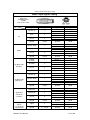
Cabling of the input channels depends strongly on the chosen configuration. The next table
describes the different possibilities of cabling and Appendix D.3 depicts the ESRF incremental
encoder adapter cabling.
Refer to the CHCFG command in Section 4.1 for further information about channels
configuration.
MUSST User Manual
13 of 100
Table 5: MUSST input signals cabling
MUSST input signals cabling
plug for the
front panel socket
LEMO®
FGG.1B.306.CLAD76
single-ended signals
signal
plug pin
signal type
mode
counter up
1
gate
3
preset
5
ground
shield
counter down
1
gate
3
preset
5
ground
shield
counter
up-down
1
direction
3
preset
5
ground
shield
counter up
1
counter down
3
preset
5
ground
shield
counter 0°
1
counter 90°
3
preset
5
ground
up
ground
shield
counter down +
counter down gate +
gate preset +
preset -
1
2
3
4
5
6
ground
shield
counter +
counter direction +
direction preset +
preset -
1
2
3
4
5
6
ground
shield
counter up +
counter up counter down +
counter down preset +
preset -
1
2
3
4
5
6
ground
shield
counter 0°+
counter 0°counter 90°+
counter 90°preset +
preset -
1
2
3
4
5
6
shield
ground
shield
signal
3
signal+
signal-
3
4
ground
4 + shield
ground
shield
down
up-down with
direction
up-down with
two inputs
quadrature
counter or
encoder
analogue
signals
(see daughter
card manual)
MUSST User Manual
differential signals
signal
plug pin
counter up +
1
counter up 2
gate +
3
gate 4
preset +
5
preset 6
14 of 100
2.2. Rear Panel
The MUSST rear panel is depicted in the following figure. The rear panel is composed by the
communication ports (GPIB and serial line), the synchronisation signal, the spectroscopy
ADC interface and the power connector. These components are described in the next subsections.
Figure 4: MUSST rear panel
MUSST User Manual
15 of 100
2.2.1. GPIB
The main communication way with MUSST is the by GPIB port (General Purpose Interface
Bus). GPIB presents both a reasonable data rate and latency time what makes it a well
compromised solution for MUSST communication.
The MUSST GPIB port only becomes active if any cable is connected to the serial line ports
(see Section 2.2.2). Whenever a connection is made to any of the serial ports, the GPIB is
disabled
In addition to the ASCII based commands, GPIB communication provides support for binary
data transfer.
For further information about communication see Appendix B.
2.2.2. Serial line ports
This connector includes two serial line ports, RS232 and RS422. Both ports have the same
function and any of them can be used for communication purposes in the same way of the
GPIB port (see Section 2.2.1). However, due to the limited data rate, serial port is not suitable
for data transfer and should be used only for diagnostics or setting needs: setting of GPIB
address, configuration of channels, etc.
It is important to note that the serial port is also used for firmware downloading purposes
during either the manufacturing or a software updating.
The serial port should be configured as follows:
Table 6: Serial port setting
Baudrate
9600
NO
Parity
Stop bits
1
The table below shows the pin-out of both RS232 and RS422 serial ports available in the rear
panel female 9-pin Sub D connector. Note that the signal direction is related to MUSST side,
i.e., “IN” means an input signal for MUSST.
Table 7: MUSST serial port connector pin-out
Female 9-pin Sub D
Pin
Signal
Direction
TXD
OUT
RXD
IN
GND
-
8
TXD+
OUT
9
TXD-
OUT
RXD+
IN
RXD-
IN
2
3
5
6
7
MUSST User Manual
Port
RS232
common
RS422
16 of 100
2.2.3. TRIG
This is a bidirectional TTL signal aimed to mainly synchronise several MUSST modules
working together. It is available through a Lemo® 00-series connector.
A positive 100ns pulse can be generated at each event occurrence in the same way of the
front panel TRIG out A signal (see Section 2.1.2).
The electrical implementation of this signal is described in Appendix C.3.
2.2.4. ADC
This is the data and control connection to spectroscopy ADCs in order to use MUSST as a
Multi-Channel Analyser.
The interface follows the specification of similar products designed by Canberra®. The
connection between MUSST and the spectroscopy ADC is made by a 34-wire ribbon cable
with a 34-pin HE10 connector in both ends.
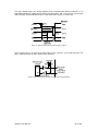
In addition to the data interface, MUSST is capable to handle the Canberra® ICB - Instrument
Control Bus – for the associated ADC configuration purposes. An auxiliar cable should be
installed internally and made accessible by a rear panel cut-out in order to use this capability
as illustrated in the figure below (see more details about this cable in Appendix D.5) .
Figure 5: MUSST rear panel connection for ICB cable
MUSST User Manual
17 of 100
The following table highlights the main differences between using the commercial solution
(Canberra® AIM + ADC) and the MUSST solution (MUSST + commercial spectroscopy ADC).
Table 8: Comparison between commercial and MUSST solution for spectroscopy
Canberra® solution
MUSST solution
Multi-Channel
Analyser module
Canberra® Model 556A AIM
Acquisition Interface Module
MUSST
Number of ADCs
up to 2
1
Acquisition Memory
128k x 16 bits
512k x 32 bits
Host communication
Ethernet
GPIB
yes
yes
yes
no
Canberra® ICB Instrument Control
Bus interface
LFC - Loss Free
Counting mode
2.2.5. NIM power supply
The MUSST module uses the +6V, +12V, +24V and -24V power supplies of the NIM crate
where it is installed.
The table below presents the MUSST power supply requirement without any daughter card
installed.
Table 9: MUSST power supply requirement without daughter card
parameter
+6V
+12V
+24V
-24V
GND
module power
MUSST User Manual
pin
10
16
28
29
34
typical values
650 mA
45 mA
10 mA
10 mA
5.5 W
18 of 100
3. OPERATION INSTRUCTIONS
This section deals with the practical aspects of the deployment of MUSST in an experimental
setup. Information about installation and main configurations of the module as well as some
practical usage tips are given in the next sub-sections.
3.1. Installation and configuration
Installation of MUSST requires connection to a host by one of the communication ports,
specification of the input, trigger and digital I/Os signals as well as specification of the
sequencer program and data storage.
A number of configuration has also to be done by means of software commands. The
configuration parameters are stored in an internal non-volatile memory that can be recovered
after an off-on cycle.
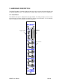
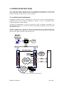
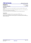
The figure below gives an overview of a generic installation where host communication, input
channels, daughter cards, digital I/Os, trigger signals and spectroscopy ADC are depicted.
The next sub-sections describe each of these items.
MUSST
MUSST
RUN
RUN
TRIG
in
TRIG
in
out A
out A
out B
out B
card
card
1
1
2
card
2
card
3
3
4
card
4
card
5
5
6
6
Figure 6: General overview of MUSST deployment
MUSST User Manual
19 of 100
3.1.1. Communication: GPIB and serial ports
Due to the limited data rate of the serial ports, the preferred communication way with MUSST
is the GPIB.
GPIB connection can be obtained by means of a PCI GPIB card or an Ethernet-to-GPIB
controller and the cable can be as long as 20 meters provided the electrical load is correctly
configured.
The MUSST modules should have an individual address ranging from 1 to 31 (default
address is 13).
The GPIB address and electrical load can be set or checked by the GPIB/?GPIB command
and request, respectively (see Section 4.1).
3.1.2. Input channels
No daughter card is necessary if the input signal observes both of the conditions below.
• the signal is electrically compatible to either single-ended TTL or differential RS422.
• the signal is to be treated as a source for an up, down, up-down or quadrature
counter (or encoder)
In this case, the signal needs only to be cabled as indicated in Section 2.1.4 and the
correspondent channel configured according to the desired mode.
The input channels can also be configured to count specific internal signals such as time,
MCA data, software or sequencer increments and trigger signals actions. In the case of time
counting, the internal timer timebase should be configured to match the desired time
resolution.
A desired value can be loaded into the channels or the timer for the usage convenience. In
the case of a counter, this value can be also preset by an external signal if the PRESET
keyword is used in the channel configuration.
If the input signal does not observe the conditions above or it observes them but any of the
available modes is not convenient for the usage, a specific daughter card is necessary. Most
common daughter cards are those that are able to deal with absolute encoder interfaces and
analogue signals (ADCs).
See the CHCFG, TMRCFG, CH and TIMER commands in Section 4.1 for a complete
description of channel and timer configuration, and channel and timer values setting,
respectively. See also the ?VAL request in the same Section for value readings.
MUSST User Manual
20 of 100
3.1.3. Digital I/Os
The digital I/Os can be used to control or to read two-state-logic devices (provided the
necessary interfacing is realised): shutter controllers, pneumatics valves, relays,
electromechanical switches.
The IO/?IO command allows setting and reading of individual or grouped bits, while the
command IOCFG is used to configure the direction of these signals. The ?VAL request can
be also used to read the value of these signals. See Section 4.1 for further information.
3.1.4. Trigger signals
The front panel trigger signals (TRIG in, TRIG out A and TRIG out B) can be used to
synchronise external instruments to MUSST and vice-versa.
The rear panel trigger signal (TRIG) is mainly used to synchronise several MUSST modules
working together.
TRIG in signal can be taken into account both by a user sequencer program or by the RUNCT
command.
TRIG out A and TRIG are controlled by the sequencer program while TRIG out B can be
controlled by both the sequencer program and by software (see command BTRIG)
Both TRIG out A and TRIG out B signals are also activated by the RUNCT command.
Refer to Section 4.1 for the mentioned commands.
MUSST User Manual
21 of 100
3.1.5. Sequencer program and data storage
For each specific application, a different program should be written for the sequencer. A high
level programming language has been created in order to facilitate this task, as described in
Section Error! Reference source not found..
The written program should be uploaded into the module through one of the communication
ports to be compiled on-the-fly by the internal compiler. An uploaded program can be listed
and cleared by the ?LIST and CLEAR commands, respectively.
Variables can be defined and used in the sequencer program and special commands are
available to handle them: VAR/?VAR to define/query variables and ?VARINFO to query
variable information.
Once the program has been compiled, it can be run and aborted by the RUN and ABORT
commands, respectively. The STOP command stops execution of the program, while the
CONT command re-runs the program from where it has been stopped. The ?RETCODE
request queries the program return code, if any.
Furthermore, debugging functionalities for the sequencer program are also available by using
breakpoints and step execution of the tested program. Breakpoints are managed by the
BREAK command and stepping is done by the STEP command, while the ?INSTR request
allows checking the current instruction.
The MUSST internal memory for data storage is shared between event data and MCA
histogram storing (see 3.1.6). Event data is the selected data stored by the sequencer
program in the internal memory.
Management of the event data memory includes the ESIZE command to set the event data
memory size, EBUFF to select the current memory buffer and EPTR to handle the memory
position pointer.
The stored data can be transferred to the host through the GPIB ASCII or binary transfer
mode (see the ?EDAT and ?*EDAT requests).
All the commands mentioned above are referenced in Section 4.1.
3.1.6. Spectroscopy ADC
Using MUSST as an MCA (Multi-Channel Analyser) requires a spectroscopy ADC connected
through a Canberra® standard data and control interface. Configuration parameters of the
ADC can be sent and received by means of the Canberra® ICB (Instrument Control Bus).
The MUSST internal storage memory for histogramming should be configured to the desired
number of channels and buffers. The stored histograms can be transferred to the host in
binary blocks through the GPIB port even during an acquisition. In addition, the buffers can be
automatically emptied next to its reading. These features optimises acquisition and data
transfer time.
See the ICB, HSIZE, HBUFF, HMEMCLR and ?HDAT/?*HDAT commands in Section 4.1 for
further information about ICB configuration, histogramming memory size, setting of buffers,
buffer clearing and histogram data transfer, respectively.
MUSST User Manual
22 of 100
3.2. Usage tips
Refer to Section 4.1 for all the commands mentioned below.
•
The ?INFO request provides a summary of the configuration parameters. It is a quick
and easy way to check the current configuration.
•
It is always useful to check the endianess (big endian/ little endian) of the host
processor if data transfer from MUSST is desired. The DFORMAT command allows
changing the way MUSST formats the data.
•
Use of alias for the channels and digital I/Os improves readability and gives the user
a more significant name for these signals. Refer to the ALIAS command for more
details.
•
The RUNCT command runs the timer, the counters and the MCA for a defined time. It
is an easy way to quickly check the good functioning of these elements.
•
When using time related functionalities (RUNCT command or time-driven events), it is
important to adapt the system timer timebase to the needed time resolution (see the
TMRCFG command). For instance, launching a 1µs counter run with the system timer
configured to 1MHz can lead to incorrect results since this value is in the limit of the
time resolution. Changing system timer to a higher frequency (10MHz or 50MHz) can
correct this problem.
•
It is quite common to have a situation where one wants to change an incremental
encoder direction sign. This can be done easily by using the INV keyword in the
correspondent channel configuration. Moreover, the INV keyword can be also used to
change the polarity of the input signals (see the CHCFG command).
•
Communication with MUSST can be an issue if the module address is already used
by another instrument in the same GPIB controller. The less disturbing solution for
the existing experimental setup is to set a new GPIB address to MUSST through the
serial line port by means of the GPIB command. Once the setting of the new address
is done, it is important to disconnect the serial port connector in order to enable the
GPIB. On the other hand, if there is no address conflict, the MUSST GPIB address
can be changed through the GPIB port as well.
MUSST User Manual
23 of 100
4. COMMAND SET
Command
ALIAS
TMRCFG
CHCFG
SSICFG
IOCFG
CH
TIMER
IO
BTRIG
?ALIAS
?TMRCFG
?CHCFG
?SSICFG
?IOCFG
?CH
?TIMER
?IO
?BTRIG
?VAL
?INFO
?DBINFO
DBCMD
CLEAR
+
?LIST
RUN
STOP
CONT
ABORT
VAR
EVENT
INCR
RUNCT
STEP
BREAK
?RETCODE
?STATE
?VAR
?BREAK
?INSTR
?VARINFO
VARINIT
ESIZE
HSIZE
EBUFF
HBUFF
EPTR
DFORMAT
HMEMCLR
?ESIZE
?HSIZE
?EBUFF
?HBUFF
?EPTR
?EDAT
?*EDAT
?HDAT
?*HDAT
?DFORMAT
?HMEMCLR
RESET
NAME
ECHO
NOECHO
ADDR
GPIB
ICB
?VER
?HDWVER
?NAME
?HELP
?ERR
?ADDR
?CHAIN
?GPIB
?ICB
MUSST User Manual
Description
Page
Define/delete/query system aliases
Set/query the timebase of the main timer
Set/query input channel configuration
Set/query the configuration of SSI input channels
Set/query the direction of the input/output TTL lines
Set/query input channel values and state
Set/query the main timer value and state
Set/query the logic values of the TTL I/O lines
Set/query the level of the TRIG out B signal
Query channel, timer and/or IO values
Query the summary of the module configuration
Query the list of installed daughter boards
Execute daughter board specific command
Delete the current program
Add program code line
List the current program and/or variables
Execute program
Stop program execution
Continue program execution
Abort program execution
Query the exit or stop code
Query the current module state
Initialise/read program variables
Enable/disable/force event generation
Increment SOFT mode counters
Run the main timer and counters
Step program
Manage/list breakpoints
Query the current program instruction
Query variable information
Reset program variables
28
73
33
68
60
31
72
59
30
74
57
39
38
36
25
61
66
71
37
26
65
69
75
47
56
67
70
29
58
77
78
Set/query event buffer size
Set/query histogram buffer size
Set/ query current event buffer
Set/ query current histogram buffer
Set/query the event memory data pointer
46
54
41
49
44
Read event data
43
Read histogram data
50
Set/query data format
Set/query histogram memory autoclear
40
53
Module reset
Query firmware version
Query hardware version
Set/query module name
Query list of available commands
Query last error
Select echo mode
Cancel echo mode
Set/query serial line address
Query secondary serial port status
Set/query GIPB address and bus load
Write/read byte from ICB bus
64
79
51
62
52
45
42
63
27
32
48
55
24 of 100
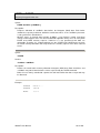
4.1. Command reference
+
Add program code line
Syntax:
+(code line)
Description:
Adds a program source code line to the current program. The line includes all the ASCII
characters after the ‘+’ sign including any white space. Program source code lines are
stored in the module internal memory and compiled on the fly.
The content of the program memory can be inspected at any time with the ?LIST query
and deleted by means of the CLEAR command.
It is possible to clear the program memory and/or load new programs or program blocks
while another program is already running in the sequencer. In this case the program lines
are compiled and stored in a temporary buffer. Whenever the running program stops or
exits, the new program is loaded into the sequencer. This feature can be used to speed up
program changes.
Examples:
Command:
CLEAR
Command:
?STATE
Answer:
NOPROG
Command:
+// This is a simple and useless program
Command:
+
Command:
+UNSIGNED A
Command:
+PROG
Command:
+
Command:
+ENDPROG
Command:
?STATE
Answer:
IDLE
Command:
?LIST
Answer:
$
// This is a simple and useless program
A = 1
UNSIGNED A
PROG
A = 1
ENDPROG
$
MUSST User Manual
25 of 100
ABORT
Abort program execution
Syntax:
ABORT
Description:
If a program is loaded in the module, this command aborts the execution and resets the
sequencer. The program remains loaded in the sequencer and can be started again either
from the beginning of from one the valid entry points.
After an ABORT command, if a valid program is loaded in memory, the module goes into
IDLE state. If there is no program, the module goes into NOPROG state. If the program is
incomplete or contains errors, the state is set to BADPROG.
Examples:
Command:
RUN
Command:
?STATE
Answer:
RUN
Command:
ABORT
Command:
?STATE
Answer:
IDLE
MUSST User Manual
26 of 100
ADDR / ?ADDR
Set/query serial line address
Syntax:
ADDR <slAddress>
Description:
Sets the serial line address to the <slAddress>. The address may be any alphanumerical
character string. The maximum length is 9 characters. Any leading zeroes in the address
are discarded.
When the serial line ports of different modules are daisy-chained for communication, a
particular module can be accessed by preceding any command with a prefix formed by the
module address followed by a colon character (:). If the first character of the address is
non-numeric, a leading zero must be added.
The serial line address is not used in GPIB communication.
Syntax:
?ADDR
Answer:
<slAddress>
Description:
Returns the serial line address of the module.
Examples:
Command:
?ADDR
Answer:
<empty>
Command:
ADDR 3
Command:
?ADDR
Answer:
3
Command:
ADDR M2
Command:
?ADDR
Answer:
M2
MUSST User Manual
27 of 100
ALIAS / ?ALIAS
Define/delete/query system aliases
Syntax:
ALIAS {CHn | IOn | <alias>} <newAlias>
ALIAS CLEAR {CHn | IOn | <alias>}
Description:
The ALIAS command sets the alias of any input channel or I/O line to the name
<newAlias>. System aliases must be a valid symbol names with a maximum length of 12
characters.
If <newAlias> has already been used as system alias for a different channel or I/O line, the
previous system alias definition is removed.
Only one system alias is allowed per input channel or I/O line. If the channel or I/O line has
already an associated system alias, the old one is discarded and replaced by the new one.
System aliases can be deleted by means of the CLEAR keyword.
Syntax:
?ALIAS [{CHn | IOn | <alias>}]
Answer:
{CHn | IOn} [<alias>]
Description:
The ?ALIAS query returns the generic specifier and the system alias associated to an
input channel or I/O line. The signal itself must be passed as parameter, either by its
generic identifier (CHn or IOn) or by its associated system alias. If there is no system alias
for the specified signal, the alias field is empty in the query answer.
If no signal is specified as parameter to the ?ALIAS query, it returns a multiline answer
with one line per each signal that has a defined alias.
Examples:
Command:
ALIAS IO3 SHCMD
Command:
?ALIAS IO3
Answer:
IO3 SHCMD
Command:
ALIAS CH1 PHI
Command:
?ALIAS
Answer:
$
CH1 PHI
IO3 SHCMD
$
MUSST User Manual
28 of 100
BREAK / ?BREAK
Manage/list breakpoints
Syntax:
BREAK ADD [{<line> | -<ucAddr>}]
BREAK {CLEAR | ENABLE | DISABLE} [{<bkn> | ALL}]
Description:
With the ADD keyword, this command adds a program breakpoint at the program source
code <line> or the at microcode instruction at address <ucAddr>. If no source code line
number or microcode address is specified, the breakpoint is set at the current program
address.
Every breakpoint is identified with incrementing numbers starting from 1. Breakpoints
preserve their numbers even if other breakpoints with lower numbers are deleted.
Breakpoints are enabled at creation time.
Breakpoints can be enabled, disabled or deleted by means of the ENABLE, DISABLE or
CLEAR keywords. These action can apply either to a single breakpoint with number <bkn>
or to all the defined breakpoints if the keyword ALL is used. Disabled breakpoints are not
active but remain in the list and can be re-enabled at later time.
Syntax:
?BREAK [<bkn>] [ASM] [CODE]
Answer:
<bkn> {+ | -} <line> <ucAddr> [: (ucode_line)] [: (source_line)]
Description:
The ?BREAK query returns the source code line number and the microcode address at
which the breakpoint with number <bkn> is placed. It also returns a character ‘+’ or ‘-‘
depending on whether the breakpoint is enabled or not. The keywords ASM and CODE
can optionally be used to make the query return the corresponding microcode
disassembled line and the source code line respectively.
If the breakpoint number <bkn> is not specified, the query returns a multiline answer with
one line per defined breakpoint.
Examples:
Command:
BREAK ADD 4
Command:
BREAK ADD -34
Command:
BREAK DISABLE 1
Command:
?BREAK
Answer:
$
1
2
$
MUSST User Manual
+
4 0x00A
11 0x022
29 of 100
BTRIG / ?BTRIG
Set/query the level of the TRIG out B output signal
Syntax:
BTRIG {0 | 1}
Description:
Sets the logic level of the TRIG out B front panel output.
Syntax:
?BTRIG
Answer:
{0 | 1}
Description:
Returns the current logic level of the TRIG out B output signal.
Examples:
Command:
BTRIG 1
Command:
?BTRIG
Answer:
1
MUSST User Manual
30 of 100
CH / ?CH
Set/query input channels
Syntax:
CH {CHn | <alias>} [<newVal>] [{RUN | STOP}]
Description:
Loads one of the input registers with the value <newVal>. The input channel may be
specified either by the generic identifier CHn or by the corresponding system alias if
defined.
In case of channels configured in counting mode, this command can also be used to start
or stop the counter by means of the RUN and STOP keywords.
Channels configured in sampling mode (ADC’s, encoders, …) are always active and
cannot be started or stopped.
Syntax:
?CH {CHn | <alias>}
Answer:
<value> {RUN | STOP}
Description:
The ?CH query returns the current value of the input channel and its RUN/STOP state.
Example:
Command:
CH CH2 34
Command:
?CH CH2
Answer:
34 STOP
Command:
CH CH2 RUN
Command:
?CH CH2
Answer:
1032 RUN
MUSST User Manual
31 of 100
?CHAIN
Query secondary serial port status
Syntax:
?CHAIN
Answer:
{YES | NO} {RS232 | RS422 | NONE}
Description:
Returns whether or not (“YES” or “NO”) there is another instrument connected to the
secondary serial port as well as its electrical specification (“RS232” or “RS422”).
The secondary serial port is the port that is not used for communications with the host
computer and that can be eventually used for daisy-chaining of modules. If no serial port is
used, the module is accessed by GPIB, the query returns “NONE” as secondary port type.
Example:
Command:
?CHAIN
Answer:
NO RS422
MUSST User Manual
32 of 100
CHCFG / ?CHCFG
Set/query input channel configuration
Syntax:
CHCFG {CHn | <alias>} [channel_config] [ALIAS <new_alias>]
with channel_config one of:
CNT {UP | DOWN} [INV] [GATE [INV]] [PRESET [INV]]
CNT UPDOWN {PULSE | DIR | QUAD {[X4] | X2 | X1}} [INV] [PRESET [INV]]
ENC {[QUAD] {[X4] | X2 | X1} | PULSE | DIR} [INV] [PRESET [INV]]
{1KHZ | 10KHZ | 100KHZ | 1MHZ | 10 MHZ | 50MHZ} [GATE [INV]] [PRESET [INV]]
{PROG | SOFT} [GATE [INV]] [PRESET [INV]]
{ITRIG | ATRIG | BTRIG | EVENT | EVSEEN | MCA} [GATE [INV]] [PRESET [INV]]
{MCALT | MCADT} [PRESET [INV]]
SSI [INV] [FILT [<n>]]
ADC {[+-10V] | +-5V | +10V} [FILT [<n>]]
Description:
Sets the configuration parameters for channel CHn. In addition to the configuration, the
CHCFG command can also be used to set the system alias for the selected channel.
Input channels can be configured to use different types of signals and/or operation modes.
Most of the possible configurations accept an external gate and preset signal. The external
preset loads the correspondent channel with the last loaded value. These features need to
be activated by means of the GATE and PRESET keywords. The optional keyword INV
following GATE and PRESET can be used to invert the polarity of the corresponding
external signal.
The available modes are:
- Generic counter (CNT). The input channel is configured as a generic counter. The
counting source is an external signal applied to the corresponding front panel
connector. The counter can be started and stopped and usually must be cleared at the
beginning of each counting interval. Possible counting modes are UP, DOWN and
UPDOWN.
In case of upward or downward counting, the channel counts the signal applied to the
IN0 line at the input connector. The polarity of the signal can be inverted by means of
the INV keyword. By default the channel counts the rising edges of the input signal.
When inverted, the falling edges are counted.
A channel configured for UPDOWN counting uses the signals applied to the IN0 and
IN1 lines of the input connector. The channel must be set in one of three possible
modes, PULSE, DIR and QUAD, depending on the type of signal it accepts.
In PULSE mode the pulses applied to the IN0 line increment the counter, while pulses
applied to IN1 decrement it. In PULSE mode the INV keyword inverts the polarity of the
input signals and not the direction (up/down) of the counter.
Is DIR mode the channel counts the pulses of the line IN0 while logic level of the IN1
line selects the counting direction (0 = downwards, 1 = upwards).
In QUAD mode the channel operates in phase counting mode. The channel counts the
edges of the IN0 and IN1 signals and the counting direction is selected by the sign of
the phase between both. The channel can be set to count 1, 2 or 4 edges per signal
period (X1, X2 and X4 keywords). See also the ENC mode.
MUSST User Manual
33 of 100
In DIR and QUAD modes, the INV keyword inverts the counting direction.
- Encoder mode (ENC). The input channel is configured as a updown counter but it is
permanently active and cannot be stopped. In this way it can be used to track an
external signal and follow its variations in time. This mode is intended primarily to be
used with incremental position encoders. The encoder mode accepts the same options
PULSE, DIR and QUAD than the updown generic counting mode (CNT UPDOWN).
The INV keyword inverts the counting direction (up/down) of the channel.
- Timer mode (1KHZ, 10KHZ, 100KHZ, 1MHZ, 10MHZ, 50MHZ). The channel is set to
operate as a timer by counting one among the six internal timebases. The selected
timebase can be different from the one selected for the system timer (see TMRCFG
command). Channels in timer mode can be gated and/or preset by external signals
applied to the IN1 and IN2 lines respectively.
- MCA timer (MCALT, MCADT). The input channel is configured to measure the live time
(MCALT) or dead time (MCADT) of the external spectroscopy ADC. The channel is
internally set to the same timebase than the system timer and the time unit is therefore
selected by the TMRCFG command.
- Special counters (PROG, SOFT, ITRIG, ATRIG, BTRIG, EVENT, EVSEEN, MCA). The
input channel is configured to count special signals or internal conditions. Possible
counting sources are the following:
PROG – The channel counter is incremented under control of the sequencer by means
of the #INC CHn program instruction.
SOFT – The channel counter is incremented by INCR command issued from the host
computer.
ITRIG, ATRIG, BTRIG – The channel counts the input or output trigger signals.
EVENT – The channel counts the event occurrences that have been produced but
have not been treated yet by the sequencer.
EVSEEN – The channel counts the event occurences that have already been treated
by the sequencer.
MCA – The channels counts all the events (MCA total counts) transferred from the
spectroscopy ADC .
- ADC mode (ADC). The input channel is loaded with digital value of the analogue voltage
applied to the input. This mode requires the installation of a specific daughter board.
The sampling period and the bit resolution depends on the daughter board installed.
With certain daughter boards, the input range can be selected between ±10V, ±5V or 010V.
The analogue value is always represented as a signed 32 bit value. The positive full
scale corresponds to the 0x7FFFFFFF digital value.
It is possible to enable an internal first order low-pass digital filter with the FILT <n>
<n>.
option. The effective filter time constant is 2 T where T is the sampling period. If the
FILT keyword is used with no argument, the digital filter is disabled.
- SSI mode (SSI). The input channel receives the digital value from an external device,
typically an absolute position encoder, through a SSI interface. This mode requires the
installation of a specific daughter board.
The digital value is aligned to the most significant bits of a signed 32 bit value
The INV keyword inverts the sign of the channel. The configuration of the SSI interface
are selected by means of the SSICFG command.
It is possible to enable an internal first order low-pass digital filter with the FILT <n>
option in the same way that in the ADC mode.
MUSST User Manual
34 of 100
Syntax:
?CHCFG {CHn | <alias>}
Answer:
channel_config [ALIAS <alias>]
where channel_config is one of the possible combinations presented above.
Description:
Returns the channel configuration and the corresponding system alias if defined. The
channel can be specified either by a channel identifier CHn or by a valid system alias.
Examples:
Command:
CHCFG CH1 ENC INV ALIAS PHI
Command:
?CHCFG PHI
Answer:
ENC INV ALIAS PHI
Command:
CHCFG PHI CNT UPDOWN DIR INV
Command:
?CHCFG PHI
Answer:
CNT UPDOWN DIR INV ALIAS PHI
Command:
CHCFG PHI 1MHZ ALIAS
Command:
?CHCFG PHI
Answer:
ERROR
Command:
?ERR
Answer:
Bla, bla, bla
Command:
?CHCFG CH1
Answer:
1MHZ
MUSST User Manual
35 of 100
CLEAR
Delete current program
Syntax:
CLEAR
Description:
Deletes the current program from the module memory. Source code and variable
declaration are lost but the module keeps executing any microcode program that was
already loaded and running in the sequencer. Program execution is aborted as soon as
the sequencer stops, either by a program exit instruction, a STOP command, a breakpoint,
etc. If in the mean time a new program has been loaded and compiled by the module, the
corresponding microcode is loaded into the sequencer.
Examples:
Command:
?STATE
Answer:
IDLE
Command:
CLEAR
Command:
?STATE
Answer:
NOPROG
MUSST User Manual
36 of 100
CONT
Continue program execution
Syntax:
CONT [<nBkpts>]
Description:
When the program is stopped (STOP or BREAK states) it can be continued by the CONT
command.
Program execution will skip the first <nBkpts> breakpoints found if this argument is
specified.
Examples:
Command:
STOP
Command:
?STATE
Answer:
STOP
Command:
CONT
Command:
?STATE
Answer:
RUN
MUSST User Manual
37 of 100
DBCMD
Execute daughter board specific command
Syntax:
DBCMD {CHn | <alias>} [{RESET|SSIRAW|SSINORM | OUT {0|1} | REG <add> <val>}]
Description:
Executes an action in the daughter board associated to channel CHn. Possible commands
and actions are:
Command
RESET
Action
Initialises the channel electronics in the daughter board
SSIRAW
In case of SSI inputs, get the status bits along with the data bits
SSINORM
In case of SSI inputs, get only data bits
OUT {0|1}
Sets the auxiliary channel digital output to 0 or 1
Sets the daughter board internal register at address addr to value val
REG addr val
Examples:
Command:
DBCMD CH3 RESET
Command:
ALIAS CH1 PHI
Command:
DBCMD PHI OUT 1
Command:
DBCMD CH5 REG 1 0xF035
Command:
DBCMD CH3 SSIRAW
MUSST User Manual
38 of 100
?DBINFO
Query the list of installed daughter boards
Syntax:
?DBINFO [*]
Description:
Returns the list of installed daughter boards. If the parameter ‘*’ is used, the request
returns in addition the current values of the configuration registers of the boards.
Examples:
Command:
?DBINFO
Answer:
$
Channels 1,2
No daughter board installed.
Channels 3,4
No daughter board installed.
Channels 5,6
Board: Universal SSI and Analog (+-10V,+-5V,+10V)
$
Command:
?DBINFO *
Answer:
$
Channels 1,2
No daughter board installed.
Channels 3,4
No daughter board installed.
Channels 5,6
Board: Universal SSI and Analog (+-10V,+-5V,+10V)
registers CH5:
CFG addr = 0 (0x41) - value = 0x0187
SSI addr = 1 (0x43) - value = 0x0000
registers CH6:
CFG addr = 0 (0x42) - value = 0x0187
SSI addr = 1 (0x44) - value = 0x0000
$
MUSST User Manual
39 of 100
DFORMAT / ?DFORMAT
Set/query data format
Syntax:
DFORMAT [{DEC | HEXA}] [{NOSWAP | BSWAP | WSWAP | WBSWAP}]
Description:
Selects the data format used by the data memory read queries.
The DEC or HEXA keywords select whether the ASCII data returned by the ?EDAT and
?HDAT queries is formatted in decimal or hexadecimal format respectively.
The swap keywords select the swapping operation applied to the 32-bit binary data
returned by the ?*EDAT and ?*HDAT queries. MUSST stores data internally in big endian
byte ordering. The possible options are:
NOSWAP - No swapping (big endian).
BSWAP
- Byte swapping. Only bytes are swapped within each 16-bit word.
WSWAP
- Word swapping. Only both 16-bit words are swapped.
WBSWAP - Word and byte swapping. Both bytes and words are swapped. (little endian)
If binary data is read into a computer with a little endian processor, like an Intel x86,
WBSWAP swapping mode should be selected.
Syntax:
?DFORMAT
Answer:
{DEC | HEXA} {NOSWAP | BSWAP | WSWAP | WBSWAP}
Description:
Returns a list of the operation flags that are currently NOT set.
Examples:
Command:
?DFORMAT
Answer:
HEXA BWSWAP
Command:
DFORMAT DEC
Command:
?DFORMAT
Answer:
DEC BWSWAP
MUSST User Manual
40 of 100
EBUFF / ?EBUFF
Set/query current event buffer
Syntax:
EBUFF [<buffN>]
Description:
Selects the current buffer used for even data storage. Valid buffer numbers <buffN> go
from 0 to <nOfBuff>-1, where <nOfBuff>is the total number of buffers available as returned
by the ?ESIZE query.
If the buffer number <buffN> is not specified, the current buffer is set to 0.
Syntax:
?EBUFF
Answer:
<buffN>
Description:
Returns the current buffer used for even data storage.
Examples:
Command:
?ESIZE
Answer:
1024 128
Command:
EBUFF 32
Command:
?EBUFF
Answer:
32
Command:
EBUFF
Command:
?EBUFF
Answer:
0
MUSST User Manual
41 of 100
ECHO
Switch echo mode on
Syntax:
ECHO
Description:
This mode is intended to be used when the instrument is connected to a dumb character
terminal through one its serial ports. In this mode the characters received by the unit are
sent back to the terminal and error messages are produced as soon as the corresponding
errors are detected.
If the instrument is controlled by a program running in host computer the echo mode
should be switched off (see NOECHO command). In this case the error messages can be
requested by means of the ?ERR query.
This command has no effect if the module is controller by the GPIB interface.
Example:
Command:
MUSST User Manual
ECHO
42 of 100
?EDAT / ?*EDAT
Read event data memory
Syntax:
?EDAT <nVal> [<buffN> [<offset>]]
?*EDAT <nVal> [<buffN> [<offset>]]
Answer:
(<nVal> data values)
Description:
Returns <nVal> data values from the event data memory area. The values start at offset
<offset> in the buffer <buffN>. If <buffN> and/or <offset> are not specified, the current
buffer number and offset are used.
The ?EDAT query returns data in ASCII format, while ?*EDAT returns them in binary
mode. The DFORMAT command can be used to select the ASCII format or the binary
swapping mode used.
Example:
Command:
DFORMAT HEXA
Command:
?EDAT 5
Answer:
$
0x00458F31
0x0047C320
0x00528F31
0xDE459F20
0xEF9A82C7
$
Command:
?*EDAT 100
Answer:
<100 32-bit binary values (400 bytes) transferred>
MUSST User Manual
43 of 100
EPTR / ?EPTR
Set/query event memory pointer
Syntax:
EPTR <offset> [<buffN>]
Description:
Sets the internal event data memory pointer to point to the data position at offset <offset>
in the buffer number <buffN>.
Syntax:
?EPTR
Answer:
<offset> <buffN>
Description:
Returns the current position of the event data memory pointer.
Example:
Command:
EPTR 0 0
Command:
?EPTR
Answer:
0 0
Command:
EPTR 100 2
Command:
?EPTR
Answer:
100 2
MUSST User Manual
44 of 100
?ERR
Query last error
Syntax:
?ERR
Answer:
{OK | <errorMessage>}
Description:
Returns the string “OK” if the execution of the last command was successful or an error
message describing the error in the last command.
Example:
Command:
?VER
Answer:
MUSST 01.00a
Command:
?ERR
Answer:
OK
Command:
?VERSION
Answer:
ERROR
Command:
?ERR
Answer:
Command not recognised.
MUSST User Manual
45 of 100
ESIZE / ?ESIZE
Set/query event buffer size
Syntax:
ESIZE <bufSize> [<nOfBuff>]
Description:
Requests allocation of <nOfBuff> data buffers for event data storage. Each buffer should
have capacity to allocate <buffSize> 32-bit data values. If the <nOfBuff> parameter is not
specified it is defaulted to 1.
MUSST shares its internal data memory (2 MByte = 512 KValues) among event data
storage and histogram data. The internal allocation algorithm always tries to satisfy both
ESIZE and HSIZE memory requests. However it is not guaranteed that both are
compatible. Therefore it is recommended to use the ?ESIZE and ?HSIZE query to check
the actual memory allocation and verify whether the memory requests have been satisfied
or not.
Syntax:
?ESIZE
Answer:
<bufSize> <nOfBuff>
Description:
Returns the actual buffer memory allocation for event data storage. Both <buffSize> and
<nOfBuff> may not be identical to the values requested by the ESIZE command.
Buffer size are always rounded to a power of 2 and more buffer than those requested may
be allocated.
Example:
Command:
ESIZE 1000
Command:
?ESIZE
Answer:
1024 1
MUSST User Manual
46 of 100
EVENT
Enable/disable/force event generation
Syntax:
EVENT {ENABLE | DISABLE | FORCE}
Description:
Sets the enable/disable event generation flag or forces an event condition.
The enable/disable event generation flag authorises or forbids the generation of events in
the module.
An event condition is generated by means of the keyword FORCE even if events were
disabled. As a side effect, after forcing an event condition the enable/disable flag is set to
ENABLE.
Syntax:
?EVENT
Answer:
{ENABLE | DISABLE}
Description:
Queries the status of enable/disable event generation flag.
Examples:
Command:
EVENT DISABLE
Command:
?EVENT
Answer:
DISABLE
Command:
EVENT FORCE
Command:
?EVENT
Answer:
ENABLE
MUSST User Manual
47 of 100
GPIB / ?GPIB
Set/query GPIB address and bus load
Syntax:
GPIB [<gpibAddr>] [{X1 | X10}]
Description:
Sets the address of the GPIB interface and the equivalent electrical load.
The address must be a number between 1 and 31.
The equivalent electrical load can be set to either one instrument (X1) or 10 instruments
(X10). The electrical load has an influence on the maximum length of the GPIB cable. The
GPIB standard specifies a maximum cable length of 2 meters per instrument connected to
the bus, the total bus length is limited to 20 meters and the number of instrument loads is
set to 15.
Therefore when the electrical load is set to X10, a single MUSST module can be
connected to a GPIB controller with a 20 meter long cable and be in full conformity with the
GPIB standard. In addition lab tests and measurements have shown that those limits can
be safely raised in practice.
Syntax:
?GPIB
Answer:
<gpibAddr> {X1 | X10}
Description:
Returns the address of the GPIB interface and the equivalent electrical load.
Examples:
Command:
GPIB 13
Command:
?GPIB
Answer:
13 X10
Command:
GPIB X1
Command:
?GPIB
Answer:
13 X1
MUSST User Manual
48 of 100
HBUFF / ?HBUFF
Set/query current histogram buffer
Syntax:
HBUFF [<buffN>]
Description:
Selects the current buffer used for histogram (MCA) data storage. Valid buffer numbers
<buffN> go from 0 to <nOfBuff>-1, where <nOfBuff>is the total number of buffers available
as returned by the ?HSIZE query.
If the buffer number <buffN> is not specified, the current histogram data storage buffer is
set to 0.
Syntax:
?HBUFF
Answer:
<buffN>
Description:
Returns the current buffer used for histogram (MCA) data storage.
Examples:
Command:
?HSIZE
Answer:
1024 128
Command:
HBUFF 32
Command:
?HBUFF
Answer:
32
Command:
HBUFF
Command:
?HBUFF
Answer:
0
MUSST User Manual
49 of 100
?HDAT / ?*HDAT
Read histogram data memory
Syntax:
?HDAT <nVal> [<buffN> [<offset>]]
?*HDAT <nVal> [<buffN> [<offset>]]
Answer:
(<nVal> data values)
Description:
Returns <nVal> data values from the histogram (MCA) memory area. The values start at
offset <offset> in the buffer <buffN>. If <buffN> and/or <offset> are not specified, the
current buffer number and offset are used.
The ?HDAT query returns data in ASCII format, while ?*HDAT returns them in binary
mode. The DFORMAT command can be used to select the ASCII format or the binary
swapping mode used.
Example:
Command:
DFORMAT DEC
Command:
?HDAT 10 2 0
Answer:
$
234
567
789
815
1434
1510
1503
1473
1100
431
$
Command:
?*HDAT 1024
Answer:
<1024 32-bit binary values (4 Kbytes) transferred>
MUSST User Manual
50 of 100
?HDWVER
Query hardware version
Syntax:
?HDWVER
Answer:
X.Y.Z / A.B
Description:
Returns the version number X.Y.Z / A.B of the MUSST hardware.
Where:
X is the main programmable logic circuit version
Y is the main printed circuit board version
Z is the main printed circuit board configuration version
A is the inputs/outputs programmable logic circuit version
B is the inputs/outputs printed circuit board version
Example:
Command:
?HDWVER
Answer:
1.0.0 / 1.0
MUSST User Manual
51 of 100
?HELP
Query list of available commands
Syntax:
?HELP
Description:
Returns the list of available commands and queries.
Example:
Command:
?HELP
Answer:
$
RESET
?HDWVER
?STATE
?RETCODE
CLEAR
?LIST
RUN
STOP
ABORT
CONT
STEP
EVENT
INCR
?EVENT
?INSTR
RUNCT
VAR
VARINIT
BREAK
ICB
TMRCFG
CHCFG
SSICFG
IOCFG
ALIAS
DBCMD
CH
TIMER
IO
BTRIG
ESIZE
HSIZE
EBUFF
HBUFF
EPTR
HMEMCLR
DFORMAT
GPIB
?VARINFO
?VAR
?BREAK
?ICB
?TMRCFG
?CHCFG
?SSICFG
?IOCFG
?ALIAS
?CH
?TIMER
?IO
?BTRIG
?VAL
?ESIZE
?HSIZE
?EBUFF
?HBUFF
?EPTR
?EDAT
?*EDAT
?HDAT
?*HDAT
?HMEMCLR
?DFORMAT
?GPIB
?INFO
?DBINFO
ECHO
NOECHO
ADDR
NAME
?ERR
?ADDR
?CHAIN
?NAME
?VER
?HELP
$
MUSST User Manual
52 of 100
HMEMCLR / ?HMEMCLR
Set/query histogram memory autoclear
Syntax:
HMEMCLR [{ON | OFF}] {FULL | [<firstBuff> [<lastBuff>]]}
Description:
Sets/clears the histogram autoclear feature by means of the ON and OFF keywords. When
the autoclear feature is set, the histogram (MCA) data memory is automatically cleared as
it is read by means of the ?HDAT or ?*HDAT queries. This feature saves time by avoiding
wasting time in filling the histogram memory buffers with zeros.
The HMEMCLR command can also be used to actually clear the histogram memory
buffers. If the <firstBuff> and <last Buff> buffer numbers are specified, the whole buffer
range from <firstBuff> to <last Buff> is cleared. If the FULL keyword is used, the whole
histogram memory area is cleared.
Syntax:
?HMEMCLR
Answer:
{ON | OFF}
Description:
Returns the histogram autoclear flag.
Examples:
Command:
?HMEMCLR
Answer:
OFF
Command:
HMEMCLR ON FULL
Command:
?HMEMCLR
Answer:
ON
MUSST User Manual
53 of 100
HSIZE / ?HSIZE
Set/query histogram buffer size
Syntax:
HSIZE <bufSize> [<nOfBuff>]
Description:
Requests allocation of <nOfBuff> data buffers for histogram (MCA) data. Each buffer
should have capacity to allocate <buffSize> 32-bit data values. If the <nOfBuff> parameter
is not specified it is defaulted to 1.
MUSST shares its internal data memory (2 MByte = 512 KValues) among event data
storage and histogram data. The internal allocation algorithm always tries to satisfy both
ESIZE and HSIZE memory requests. However it is not guaranteed that both are
compatible. Therefore it is recommended to use the ?ESIZE and ?HSIZE query to check
the actual memory allocation and verify whether the memory requests have been satisfied
or not.
Syntax:
?HSIZE
Answer:
<bufSize> <nOfBuff>
Description:
Returns the actual buffer memory allocation histogram (MCA) data. Both <buffSize> and
<nOfBuff> may not be identical to the values requested by the HSIZE command.
Buffer size are always rounded to a power of 2 and more buffer than those requested may
be allocated.
Example:
Command:
HSIZE 1000
Command:
?HSIZE
Answer:
1024 1
MUSST User Manual
54 of 100
ICB / ?ICB
Write/read byte from ICB bus
Syntax:
ICB <icb_addr> <databyte>
Description:
Writes the byte <databyte> at the address <icb_addr> in the ICB bus.
Syntax:
?ICB <icb_addr>
Answer:
<databyte>
Description:
Reads and returns the content of the address <icb_addr> from the ICB bus.
Examples:
Command:
ICB 5 31
Command:
?ICB 5
Answer:
31
MUSST User Manual
55 of 100
INCR
Increments SOFT mode channels
Syntax:
INCR [<cnt>]
Description:
Increments all the input channels configured in SOFT mode by <cnt> counts. If <cnt> is
not specified the SOFT counters are incremented by 1.
Examples:
Command:
?CHCFG CH1
Answer:
SOFT
Command:
?CH CH1
Answer:
0 RUN
Command:
INCR 5
Command:
?CH CH1
Answer:
5 RUN
MUSST User Manual
56 of 100
?INFO
Query module configuration
Syntax:
?INFO
Description:
Returns a multiline answer with the current configuration.
The information is presented as a list of valid commands with the appropriate parameters
that can be sent back to the module in the case that reconfiguration is needed.
Example:
Command:
?INFO
Answer:
$
MUSST 01.00 - Current settings:
NAME "no name"
ADDR ""
MUSST 01.00 - Current settings:
NAME "no name"
ADDR ""
TMRCFG 1MHZ
ALIAS CLEAR
CHCFG CH1 CNT
CHCFG CH2 ENC ALIAS PHI
CHCFG CH3 CNT
CHCFG CH4 CNT
CHCFG CH5 CNT
CHCFG CH6 CNT
IOCFG 0xFF00
ALIAS IO3 SHUTCMD
ALIAS IO12 SHUTSTATE
DFORMAT HEXA WBSWAP
HMEMCLR ON
GPIB 13 X10
$
MUSST User Manual
57 of 100
?INSTR
Query current program instruction
Syntax:
?INSTR [TIME] [CODE] [ASM]
Answer:
<line_n> <uc_addr> [<time>ns] [: <ucode>] [: <line>]
Description:
Returns the number <line_n> of the program line and the microcode address <uc_addr> of
the current instruction. This command can only be issued when the sequencer is not
executing a program. The current instruction is the next to be executed.
If the TIME keyword is passed as parameter and sequencer was stopped after running in
stepping mode, the query returns also the execution time in nanoseconds.
The keywords ASM and CODE keywords can be optionally used to request the
disassembled microcode of the current instruction and the source code of the
corresponding program line respectively.
Example:
Command:
?INSTR
Answer:
4 0x009
Command:
?INSTR ASM CODE
Answer:
4 0x009 : #JZ 0x00B : IF B == 1 THEN
MUSST User Manual
58 of 100
IO / ?IO
Set/query logic values of I/O lines
Syntax:
IO { <ioVal> [<ioMask>] | IOn | !IOn | ~IOn | <bitAlias> | !< bitAlias >| ~< bitAlias >} …
Description:
Sets I/O lines to the specified logic values (1’s or 0’s). The I/O lines can be specified either
as bit blocks or by individual identifiers. Only the output lines are affected by this
command. If an input line is specified to be set to a certain logic value, the command is
accepted but there is no effect.
Blocks of logic lines are specified by pairs <ioVal>, <ioMask> of 16-bit binary values.
<ioVal> contains the binary values of the 16 I/O lines, while <ioMask> is a bit mask that
selects which lines are actually affected. Only those output lines whose corresponding bits
in <ioMask> are 1 are set to the corresponding value in <ioVal>. If <ioMask> is not
specified, all the output bits are set to their values in <ioVal>.
Individual bits can be specified either by generic identifiers IOn or by valid system alias. If
a bit identifier is present in the parameter list with no preceding character, the bit is set to
the logic level 1. If the identifier is preceded by a ‘!’ character, the output line is set to the
logic level 0. The logic values of output lines can be toggled if their bit identifiers are
preceded by the character ‘~’.
Syntax:
?IO [{IOn | <bitAlias> | $IO}] …
Answer:
{0 | 1} …
Description:
Returns the logic values of I/O lines. The values of individual lines are requested by
generic identifiers IOn or by valid system alias and are returned as the digits 0 and 1. The
values of all the I/O lines can be requested by the $IO keyword and are returned as a 16bit value in hexadecimal format.
More than one bit or $IO block can be requested in the same ?IO query. Values are
returned in the same order than requested in the argument list.
Examples:
Command:
ALIAS IO4 SHOPEN
Command:
IO !SHOPEN IO2 ~IO1
Command:
IO 0x0003 0x000F
Command:
?IO SHOPEN $IO IO2
Answer:
0 0x0007 1
MUSST User Manual
59 of 100
IOCFG / ?IOCFG
Set/query direction I/O lines
Syntax:
IOCFG <dirMask>
Description:
Sets the direction (input or output) of the I/O lines provided the configuration is not
hardware blocked.
The 16 I/O lines are divided in 4 groups of 4 lines and the direction of each group is
defined by the 16-bit mask <dirMask>.
Direction setting of each line inside a group is not allowed: all of the 4 lines should be
configured either as inputs or outputs. This limits the possible values of <dirMask> to
0x0000, 0x000F, 0x00F0, 0x00FF, 0x0F00, 0x0F0F, 0x0FF0, 0x0FFF, 0xF000, 0xF00F,
0xF0F0, 0xF0FF, 0xFF00 (default value), 0xFF0F, 0xFFF0 and 0xFFFF.
th
th
If the n bit in <dirMask> is set to 1, the n I/O line is configured as an output. Conversely,
a bit set to 0 configures the correspondent I/O line as an input.
Syntax:
?IOCFG
Answer:
<dirMask>
Description:
th
Returns the direction of the I/O lines as the 16-bit mask <dirMask>. If the n I/O line is
th
configured as output, the n bit in <dirMask> is set to 1, otherwise it is set to 0.
Examples:
Command:
IOCFG 0xFF00
Command:
?IOCFG
Answer:
0xFF00
MUSST User Manual
60 of 100
?LIST
Query program code
Syntax:
?LIST [CODE] [NUM] [ERR] [ASM] [PFX] [VAR]
Description:
Returns program currently loaded in the module. The optional flags are:
CODE
- Lists source code lines.
NUM
- Lists line numbers both for source code and disassembled microcode.
ASM
- Lists disassembled microcode.
PFX
- Adds a ‘+’ prefix to all the source code lines
ERR
- Lists program errors.
VAR
- List program variables.
Example:
Command:
?LIST CODE ASM NUM
Answer:
$
MUSST 01.00 - Current settings:
NAME "no name"
SRANGE 0 10
SPEED 2 50
INHIBIT OFF LOW
$
MUSST User Manual
61 of 100
NAME / ?NAME
Set/query module name
Syntax:
NAME <appName>
Description:
Sets the internal module name to the ASCII string <appName>. This name is only used for
identification purposes and user convenience.
The maximum length is 20 characters.
Syntax:
?NAME
Answer:
<appName>
Description:
Returns the application name field.
Examples:
Command:
NAME DEV01
Command:
?NAME
Answer:
DEV01
Command:
NAME “Main Synchro Unit”
Command:
?NAME
Answer:
Main Synchro Unit
MUSST User Manual
62 of 100
NOECHO
Cancel echo mode
Syntax:
NOECHO
Description:
Switches the echo mode off. See the ECHO command for more details. Only applies for
serial line communication.
Example:
Command:
MUSST User Manual
NOECHO
63 of 100
RESET
Module reset
Syntax:
RESET [DEFAULT]
Description:
With no parameters this command reinitialises the module keeping the current
configuration. With the DEFAULT parameter it also resets the internal configuration and
the non-volatile memory to default values.
Examples:
Command:
MUSST User Manual
RESET
64 of 100
?RETCODE
Query exit or stop code
Syntax:
?RETCODE [LAST]
Answer:
{<retCode> | <bkpN> | <errMsg>}
Description:
If the module is coming from an EXIT or STOP statements, this query returns the exit or
stop code <retCode>. If there was not return code it returns an empty string.
If the module is in the BREAK state, ?RETCODE returns the breakpoint number <bkpN>.
If it is in ERROR state, this query returns the string <errMsg> describing the error
condition.
If the LAST keyword is used, the query returns the value returned by the last EXIT or
STOP statements.
Example:
Command:
?RETCODE
Answer:
23
MUSST User Manual
65 of 100
RUN
Execute program
Syntax:
RUN [<entryPoint>] [<nBreakP>]
Description:
With no parameters this command starts execution of the main program loaded in the
module. The main program is the “anonymous” one with no name defined in the PROG
declaration. By default, execution starts at the first line of the program.
The <entryPoint> parameter is a program name or a program label that indicates the point
from where the execution should be carried out.
The program execution is stopped by breakpoints. However, a defined number of
breakpoints can be skipped during the execution by means of the <nBreakP> parameter.
Examples:
Command:
MUSST User Manual
RUN MYPROG 5
66 of 100
RUNCT
Run counters
Syntax:
RUNCT [<ctTime>]
Description:
Starts the system timer, all the counting channels and the MCA. All the counting channels
are previously cleared.
If the counting time <ctTime> is specified, the counters run for that time. The counting time
<ctTime> unit is given by the system timer timebase. If no counting time is specified, the
system waits for an external gate signal applied to the front panel TRIG in connector.
A 100ns pulse is generated at TRIG out A in both beginning and end of counting time. In
its turn, TRIG out B is set to high logic level during the counting time.
Examples:
Command:
MUSST User Manual
RUNCT 1000000
67 of 100
SSICFG / ?SSICFG
Set/query the configuration of SSI input channels
Syntax:
SSICFG {CHn|<alias>} [nb] [fclk] [delay] [{ACTIVE|PASSIVE}] [{BINARY|GRAY}] [stb]
where fclk is one of:
{25MHZ | 12.5MHZ | 5MHZ | 2.5MHZ | 1.25MHZ | 500KHZ | 250KHZ | 125KHZ}
and delay one of:
{NODELAY | 5US | 10US | 20US | 30US | 50US | 100US | 500US}
Description:
Sets the configuration parameters for an SSI input. The SSI mode requires that a daughter
board with the required capabilities is installed for the particular channel and that the mode
has been selected by means of the CHCFG command.
The number of data bits is set to nb and the coding to either BINARY or GRAY. The
interface can be configured in ACTIVE or PASSIVE modes. When the channel is set in
active mode, MUSST generates the transfer clock that is sent to the external device. The
clock frequency is set to fclk and the time delay between data frames is set to delay. In
passive mode MUSST only listens to the clock and data lines and both fclk and delay have
no effect.
The pattern of status bits is described by the string stb. The string must include as many
dot (‘.’) characters as status bits are in the SSI frame (from 1 to 8). Certain dot characters
in the string stb may be substituted by the ‘S’, ‘E’ or ‘O’ to instruct MUSST to process the
stop or parity bits. The last character corresponds always to the stop bit and if it is
represented by ‘S’ in the status bit string, the stop bit is checked at every data frame. If
one of the other status bits is a parity bit, it may be used to check the data integrity. In the
case that there is a parity bit and it is identified in the string stb either by the ‘E’ or ‘O‘
characters, a parity check is performed to verify the data integrity. The parity is assumed to
be even or odd depending on which of the two characters is used..
Syntax:
?SSICFG {CHn | <alias>}
Answer:
nb fclk delay {ACTIVE | PASSIVE} {BINARY | GRAY} stb
Description:
Returns the configuration of the SSI interface for channel CHn.
Examples:
Command:
SSICFG CH3 24 PASSIVE ..S
Command:
?SSICFG CH3
Answer:
24 5MHZ NODELAY PASSIVE BINARY ..S
Command:
SSICFG CH3 100US GRAY E..
MUSST User Manual
68 of 100
?STATE
Query module state
Syntax:
?STATE [RETCODE]
Answer:
<state> [{<retCode> | <bkpN> | <errMsg>}]
Description:
Returns the current state of the module as one of the following strings:
State
NOPROG
No program loaded in the sequencer
Meaning
BADPROG
Program loaded in the module but not valid (errors or incomplete).
IDLE
Program loaded in the sequencer and ready to run.
RUN
Program running.
BREAK
Program stopped at a breakpoint.
STOP
Program halted at a STOP line, by a STOP command or after stepping.
ERROR
Program exception occurred (stack overflow, array index out of bounds).
The RETCODE keyword can be used to request the associated return code. Depending
on the current state of the module, the return code will be the exit or stop code <retCode>,
the breakpoint number <bkpN> or the error message <errMsg> as it would be returned by
the ?RETCODE query.
Example:
Command:
?STATE
Answer:
IDLE
Command:
?RETCODE
Answer:
327
Command:
?STATE RETCODE
Answer:
IDLE 327
MUSST User Manual
69 of 100
STEP
Step program
Syntax:
STEP [{<nLines> | -<nInstr>}]
Description:
Executes program in stepping mode for <nLines> program lines or <nInstr> microcode
instructions.
Examples:
Command:
STEP
Command:
STEP 10
Command:
STEP -1
MUSST User Manual
70 of 100
STOP
Stop program execution
Syntax:
STOP
Description:
Stops program execution. Execution can be continued by the CONT command.
Examples:
Command:
RUN
Command:
?STATE
Answer:
RUN
Command:
STOP
Command:
?STATE
Answer:
STOP
Command:
CONT
Command:
?STATE
Answer:
RUN
MUSST User Manual
71 of 100
TIMER / ?TIMER
Set/query main timer value
Syntax:
TIMER [<newValue>] [{RUN | STOP}]
Description:
Loads the system timer with the value <newValue>. This command can also be used to
start or stop the timer by means of the RUN and STOP keywords.
Syntax:
?TIMER
Answer:
<value> {RUN | STOP}
Description:
Returns the current timer value an its running state.
Examples:
Command:
TIMER 0 STOP
Command:
?TIMER
Answer:
0 STOP
Command:
TIMER RUN
Command:
?TIMER
Answer:
1897446 RUN
MUSST User Manual
72 of 100
TMRCFG / ?TMRCFG
Set/query main timer timebase
Syntax:
TMRCFG {1KHZ | 10KHZ | 100KHZ | 1MHZ | 10MHZ | 50MHZ}
Description:
Selects the frequency of the timebase used by the system timer.
Syntax:
?TMRCFG
Answer:
{1KHZ | 10KHZ | 100KHZ | 1MHZ | 10MHZ | 50MHZ}
Description:
Returns the current timebase used by the system timer.
Examples:
Command:
TMRCFG 1MHZ
Command:
?TMRCFG
Answer:
1MHZ
MUSST User Manual
73 of 100
?VAL
Query channels, timer and/or I/O values
Syntax:
?VAL [{TIMER | CHn | IOn | <alias> | $IO | $MCA | $ALL} …]
Answer:
Answer: <value> …
Description:
The ?VAL query returns current values of the system timer, the input channels or the I/O
lines. The query arguments are treated as a list of requested values. ?VAL returns the
current values in the same order as they are present in the argument list.
Input channel and I/O lines can be specified either by means of generic identifiers CHn
and IOn, or by system aliases. The system timer must be specified by the built-in alias
TIMER.
The full block of I/O lines can be requested as a single 16-bit value by means of the $IO
keyword.
The $MCA keyword can be used to request the following 4 values related to MCA
acquisition: the system timer, the total number of MCA counts, the MCA lifetime and the
MCA deadtime. The last three correspond to input channels configured in MCA, MCALT
and MCADT modes respectively. See the CHCFG command for details. If no channels are
configured in any of those modes, the corresponding value is returned by the ?VAL query
is -1. If more that one input channel is configured in the same MCA related mode,
something that is probably useless but possible, only the value of the first one is used.
The $ALL keyword can be used as a shortcut to request the values of the system timer
and all the input channels and I/O lines. In practice the $ALL keyword returns 8 values and
is equivalent to the sequence: TIMER CH1 CH2 CH3 CH4 CH5 CH6 $IO.
?VAL queries with no arguments are interpreted as ?VAL $ALL.
Examples:
Command:
?ALIAS
Answer:
$
CH1 PHI
IO3 SHCMD
$
Command:
?VAL CH3 IO11 TIMER SHCMD
Answer:
87363543 0 16738372 1
Command:
?VAL
Answer:
16738372 14564 -5353667 0 87363543 34556 0 0x0F70
Command:
?VAL PHI $IO
Answer:
-5353667 0x0F70
Command:
?VAL $MCA
Answer:
16738372 34556 -1 -1
MUSST User Manual
74 of 100
VAR / ?VAR
Write/read program variables
Syntax:
VAR <varName> <varValue>
VAR <arrayName>[array_range] {value_list | function(par, …)}
Description:
Loads the program scalar variable <varName> with the value <varValue> or a range of the
array <arrayName> with a set of values.
Array ranges are specified by subarray syntax in the form of array[<i>:<f>] where <i> and
<f> are the first and last elements of the array range to load. If <i> and <f> are not
specified, the whole array is loaded.
A program array can be loaded either by a list of values or by the result of evaluation of an
initialisation function. The list of values is a comma separated set of numbers delimited
between curly brackets. The number of values in the list must match the number of array
elements to load.
Array initialisation functions require as arguments at least the first and last value to load in
the array range. It calculates the intermediate values following the appropriate functional
dependence. Initialisation functions may need additional arguments. The available
functions are:
FILL(<v0>, <v1>) - Fills the array or subarray with values uniformly distributed
between <v0> and <v1>.
BRAGG(<th0>, <th1>, <th0deg>) - Assumes that the array or subarray is to be
loaded with values corresponding to the diffraction angle of a crystal that must fulfil the
Bragg law. The angle goes from <th0> to <th1> in MUSST units, that should always be
integer numbers. The module fills the array or subarray with angle values that correspond
to constant photon energy intervals. The BRAGG() function requires an additional floating
point argument <th0deg> that must correspond to the initial angle <th0> but expressed in
degrees.
Syntax:
?VAR {<varName> | <arrayName>[array_range]}
Answer:
<varValue> or a multiline answer with all the values of the subarray elements.
Description:
Returns the current value of the program variable <varName> or a range of elements of
the array <arrayName>[].
Examples:
Command:
?VARINFO MYVAR
Answer:
1 SIGNED
Command:
VAR MYVAR -55
Command:
?MYVAR
MUSST User Manual
75 of 100
Answer:
-55
Command:
?VARINFO MYARR
Answer:
10 UNSIGNED
Command:
?VAR MYARR[2:5]
Answer:
$
0
0
0
0
$
Command:
VAR MYARR[2:5] FILL(30, 40)
Command:
?VAR MYARR[2:5]
Answer:
$
30
33
37
40
$
MUSST User Manual
76 of 100
VARINFO
Query variable information
Syntax:
?VARINFO <varName>
Answer:
<nElem> [[ALIAS {TIMER | CHn | IOn}] {SIGNED | UNSIGNED | BOOLEAN}]
Description:
Returns the number of data elements <nElem> of the program variable <varName> and its
type. The number of elements is 1 for scalar variables and the corresponding vector length
for arrays.
If the variable is a program or system alias, the ?VARINFO query returns the ALIAS
keyword and the channel or I/O line identifier.
Examples:
Command:
?VARINFO MYARR
Answer:
10 UNSIGNED
Command:
?VARINFO PHI
Answer:
1 ALIAS CH2 SIGNED
MUSST User Manual
77 of 100
VARINIT
Reset program variables
Syntax:
VARINIT [<varName> …]
Description:
Forces the unit to reload the list of program variables <varName> with their initial values.
Variables with no explicit initial value are set to zero.
If the list of variables is missing, the VARINIT command reloads all the variables in the
current program.
Examples:
Command:
VARINIT MYVAR1 MYVAR2
Command:
VARINIT
MUSST User Manual
78 of 100
?VER
Query firmware version
Syntax:
?VER
Answer:
MUSST XX.YYa
Description:
Returns the version number XX.YY of the firmware.
Example:
Command:
?VER
Command:
MUSST 01.00
MUSST User Manual
79 of 100
Appendix A. MUSST COMMAND QUICK REFERENCE
CONFIGURATION
ALIAS {CHn | IOn | <alias>} <new_alias>
ALIAS CLEAR [{CHn | IOn | <alias>}]
?ALIAS [{CHn | IOn | <alias>}]
Define/delete/query system aliases
TMRCFG {1KHZ | 10KHZ | 100 KHZ | 1MHZ | 10MHZ | 50MHZ}
?TMRCFG
Set/query the timebase of the main timer
CHCFG {CHn | <alias>} [chan_source] [options] [ALIAS [<new_alias>]]
?CHCFG {CHn | <alias>}
Set/query the configuration of input channels
SSICFG {CHn|<alias>} [nbit] [clk] [delay] [{ACTIVE|PASSIVE}][{BINARY|GRAY}] [<stbts>]
?SSICFG {CHn | <alias>}
Set/query the configuration of SSI input channels
IOCFG <dir_mask>
?IOCFG
Set/query the direction of the input/output TTL lines
CH {CHn | <alias>} [<new_value>] [{RUN | STOP}]
?CH {CHn | <alias>}
Set/query input channel values and state
TIMER [<new_value>] [{RUN | STOP}]
?TIMER
Set/query the main timer value and state
IO {<ioval> [<iomask>], IOn, !IOn, ~IOn, <alias>, !<alias>}, ~<alias>} ......
?IO [{IOn | <bitalias>} ...]
Set/query the logic values of the TTL I/O lines
BTRIG {0 | 1}
?BTRIG
Set/query the logic value of the TRIG B output signal
?VAL [{TIMER | CHn | IOn | <alias> | $IO | $MCA | $ALL} ...]
Query channel, timer and/or IO values
?INFO
Query the summary of the module configuration
?DBINFO [*]
Query the list of installed daughter boards
DBCMD {CHn | <alias>} [{RESET | SSIRAW | SSINORMAL | OUT {0|1} | REG <add> <val>}]
Execute daughter command specific command
PROGRAM CONTROL
CLEAR
Delete the current program
+program_line
Add a new code line to the current program
?LIST [CODE] [PFX] [ASM] [NUM] [ERR] [VAR]
List the current program and/or variables
RUN [<entry_point>] [<n_bkp>]
Execute program and skip <n_bkp> breakpoints (default is 0)
STOP
Stop program execution
CONT [<n_bkp>]
Continue program execution and skip <n_bkp> breakpoints (default is 0)
ABORT
Abort program execution
?RETCODE [LAST]
Query the exit or stop code
?STATE [RETCODE]
Query the current module state. Possible states are:
NOPROG - No program is loaded in the sequencer
PROG
- A program is loaded in the unit but not in the sequencer
IDLE
- A program loaded in sequencer
RUN
- The loaded program is running
BREAK - The program is stopped at a breakpoint
STOP
- The program is stopped (after STOP, breakpoint, STEP instruction, …)
ERROR - A program exception occurred (stack overflow, ...)
VAR <var_name> <value>
VAR <array_name>[<range>] {value_list | function(pars, ...)}
?VAR <var_name>
?VAR <array_name>[<range>]
Initialise/read program variables. Sub-array syntax and initialisation functions (FILL(), BRAGG(), …) are
allowed
MUSST User Manual
80 of 100
EVENT {ENABLE | DISABLE | FORCE}
?EVENT
Enable/disable/force event generation
INCR [<cnt>]
Increment counters configured in SOFT mode
RUNCT [<timer_cts>]
Run the main timer, counters and multichannel scaler for <timer_cts> or driven by an external gate
DEBUGGING
STEP [<entry_point>] {<n_lin> | -<n_inst>}
Step the program by <n_lin> program lines or <n_inst> microcode instructions
BREAK {ADD [<line>] | {CLEAR | ENABLE | DISABLE} [{<bkn> | ALL}]}
?BREAK [<bkn>] [ASM] [CODE]
Manage/list breakpoints
?INSTR [CODE] [ASM]
Query the current program instruction
?VARINFO <var_name>
Query the dimension and the type of the variable <var_name>
VARINIT [<var_name> …]
Forces the unit to reset a list of variables to their initial values
DATA BUFFERS
ESIZE <buffer_size> [<n_of_buffers>]
?ESIZE
Set/query the size and number of memory buffers allocated to event storage.
HSIZE <buffer_size> [<n_of_buffers>]
?HSIZE
Set/query the size and number of memory buffers allocated to MCA storage.
EBUFF [<buffer_no>]
?EBUFF
Set/ query the buffer number currently selected for event storage
HBUFF [<buffer_no>]
?HBUFF
Set/query the buffer number to be used for MCA storage
EPTR [<data_point> [<buffer_no>]]
?EPTR
Set/query the data point and buffer number to be written at the next event storage
?EDAT <nval> [<buffer_n> [<first_addr>]]
?*EDAT <nval> [<buffer_n> [<first_addr>]]
Read <nval> values from <buffer_n> in the event storage memory area
?HDAT <nval> [<buffer_n> [<first_addr>]]
?*HDAT <nval> [<buffer_n> [<first_addr>]]
Read <nval> values from <buffer_n> in the histogram storage memory area
DFORMAT [{HEXA | DEC}] [{NOSWAP | BSWAP | WSWAP | WBSWAP}]
?DFORMAT
Set/query the format of the ?EDAT, ?*EDAT, ?HDAT, ?*HDAT commands
HMEMCLR [{ON | OFF}] {FULL | [<first_buffer> [<last_buffer]]}
?HMEMCLR
Set/query the autoclear mode (ON or OFF) for access to the histogram memory or clear the specified
histogram memory buffers
SYSTEM
RESET [DEFAULT]
Module reset
?VER
Query the firmware version
?HDWVER
Query the hardware version as “x.y.z / a.b”
NAME
?NAME Set/query the module name
?HELP
Query the list of available commands
?ERR
Query last error
ECHO
NOECHO Select/cancel echo mode
ADDR
?ADDR Set/query the serial line address
?CHAIN
Query the secondary serial port status
GPIB [<addr>] [{x1 | x10}]
?GPIB
Set/query the GIPB address and/or the bus load
ICB <icb_address> <databyte>
?ICB <icb_address>
Write/read a single data byte to from the ICB bus
MUSST User Manual
81 of 100
Appendix B. COMMUNICATION PROTOCOL
This section covers the communication protocol implemented in a number of instruments
developed in the Instrument Support Group at the ESRF. An instrument that adheres to this
protocol and conventions is referred as an isgdevice. The information is presented here in a
generic way and most of the information applies to any isgdevice. Some of the options, like
GPIB communication or binary transfer, may not be implemented in a particular instrument
and therefore the related information should be ignored.
B.1. Communication port
An isgdevice is equipped with one or more communication ports. A communication port may
be an asynchronous serial line or a GPIB interface. The type and number of ports as well as
the electrical interface (RS232 or RS422) depend on the particular instrument.
In the most general case an isgdevice is equipped with a RS232 port, a RS422 port and a
GPIB interface.
B.1.1. Serial line ports
Serial line ports are asynchronous serial ports electrically compatible with either the RS232 or
RS422 specification. In most of the isgdevices there are two serial ports available, one of
each type. Any of the ports can be used to communicate with the host computer.
The primary port is the one through which the isgdevice receives commands and requests.
There is no special configuration procedure to select the primary port. After power-up the
device listens to all the available ports and the first one it receives valid data through is
selected as primary. All other ports are treated as secondary.
A secondary serial line port in an isgdevice can be used to connect another isgdevice. In this
way an unlimited number of isgdevices can be connected in a daisy chain configuration and
controlled from a single primary communication port. The following figure shows an example
of a host computer communicating to three different devices using this feature.
serial line
port A
serial line
port A
port B
port B
serial line
host
isgdevices
Figure 7: isgdevices
MUSST User Manual
82 of 100
The serial ports operate at the following settings:
Baudrate
Parity
Stop bits
9600
NO
1
In normal mode command and response messages are transferred as lines of printable ASCII
characters. The only exception is binary transfer, a special feature described in B.6 only
supported by a few isgdevices.
Commands messages sent to an isgdevice by a serial port must be formatted as sequences
of printable characters terminated by a “carriage return” (ASCII 0x0D). Additional control
characters, like “line feed”, are ignored.
Response messages produced by the device consist on lines terminated by a “carriage
return” + “line feed” character sequence (ASCII 0x0D 0x0A).
B.1.2. GPIB interface
Some isgdevices include a communication interface compliant with the GPIB (IEEE-488.1)
standard. Every isgdevice with this type of interface has a default GPIB address. The
procedure for changing the address as well as the default value depends on the type of
device. The addressing conventions and characters described in B.2.2 only apply to serial line
communication and should not be used when the isgdevice is accessed by its GPIB interface.
Command messages sent to the device must be always terminated by an EOI bus signal or a
terminator character. Both characters “carriage return” (ASCII 0x0D) and “line feed” (ASCII
0x0A) may be used as message terminators.
Response messages produced by the device when it is addressed as talker consist on lines
terminated by a “carriage return” + “line feed” character sequence (ASCII 0x0D 0x0A) as in
the case of serial lines. The EOI bus signal is activated with the last character of every
message line.
MUSST User Manual
83 of 100
B.2. Syntax conventions
In the most usual case remote control is implemented by an application program running in a
host computer that sends commands and requests to the isgdevice as sequences of ASCII
characters. The syntax rules are described below. See B.5 for practical examples.
B.2.1. Commands and requests
Command lines consist of a command keyword optionally followed by parameters.
- The number and type of parameters depend on the particular command.
- The way a command line is terminated depends on the type of communication port
(see B.1).
Command keywords are not case sensitive.
- The device converts internally all the characters to uppercase before any syntax
checking.
- Parameters are also converted to uppercase unless they are enclosed between
double quotes (””, ASCII 0x22).
Commands may be optionally preceded by the acknowledge character.
- The acknowledge character is a hash symbol (#, ASCII 0x23) that must appear in the
command line immediately before the first character of the command keyword.
Normal (non query) commands never produce response messages unless the
acknowledge character is used.
- Non query command keywords always start by an alphabetical character (A to Z).
Exceptions are binary transfer commands (see B.6) that start by an asterisk character
(*, ASCII 0x2A).
- If the acknowledge character is used, the device produces the response string OK if
the command execution was successful.
- If the acknowledge character is used and the command does not executes
successfully, the device produces either the string ERROR or a string containing a
human readable error message. The behaviour depends on the current setting of the
echo mode (see B.4).
Requests are query commands that produce response messages from the device.
- Requests keywords always start by a question mark character (?, ASCII 0x3F).
- If the request is successful the content of the response message depends on the
particular request.
- If request fails the device produces either the string ERROR or a string containing a
human readable error message. The behaviour depends on the current setting of the
echo mode (see B.4).
- The acknowledge character has no effect when used with requests.
Response messages consist of one or more ASCII character lines.
- The way every line in a response message is terminated depends on the type of
communication port (see B.1).
- A response message may contain either the output of a request,
acknowledgement keyword (OK or ERROR) or a human readable error message.
an
- When a response message consists of more than one line, the first and last lines
contain a single dollar character ($, ASCII 0x3F).
MUSST User Manual
84 of 100
B.2.2. Addressing
The addressing features allow to dialogue with more than one isgdevice connected by
the serial line ports in a daisychain configuration (see B.1.1). All the addressing
prefixes and characters described in this section do not apply for GPIB communication
and should not be used in that case.
- If the command line does not include any addressing character, the command is
accepted and executed by the first device in the communication chain.
Commands and requests may be preceded by any number of skip characters and/or an
addressing prefix.
The skip character is the “greater than” symbol (>, ASCII 0x3E) and can be used to
address an isgdevice placed at a given physical position in the communication chain.
- When a device founds a skip character as the first character of a command line, it
ignores the content of the line and forwards the remaining characters to the next
device in the communication chain.
- If a host computer connected to a chain of isgdevices, sends a command line starting
with n skip characters, the n first devices in the chain will ignore the command. The
command line with the skip characters removed will be forwarded to the n+1 device in
the chain.
An addressing prefix consists of an optional alphanumerical address string followed by
a colon character (:, ASCII 0x3A).
- The address string must start by a numeric character (0-9) and consists of any
combination of numbers and alphabetical (A-Z) characters.
- A command line with an address string will be interpreted and executed only by the
first device in the communication chain whose internal address matches the one in
the address string.
- Once one of the devices recognises the address string as its own, the command line
will not be further forwarded to the remaining devices in the chain.
- Leading zeros in the address string are ignored for identification purposes but can be
used to access isgdevices whose internal address begins with a non-numeric
character.
An addressing prefix consisting of only the colon character (:) with no address string is
interpreted as a broadcast command. In that case the command line is forwarded to all
the devices in the communication chain.
MUSST User Manual
85 of 100
B.3. Common commands
The following commands are implemented in all isgdevices regardless of their specific
functionality:
Command
Description
ECHO
Activates the echo mode.
Must be used only in interactive mode with dumb terminals (see B.4).
NOECHO
Cancels the echo mode.
Echo mode should not be active when the device is controlled by a
computer program (see B.4).
?ERR
Returns the error message corresponding to the last command or request
issued to the device.
Returns the keyword OK if no error happened during the last command.
ADDR <devaddr>
Sets the module address to the string <devaddr>.
Any leading zeroes are removed from <devaddr>. It can be formed by
any combination of up to 9 alphanumerical characters.
?ADDR
Returns the current address of the device.
If no address has been set, returns an empty string.
?CHAIN
Returns the status and type of the secondary communication port.
The status indicates if there is another isgdevice connected to the
secondary port by the strings YES or NO.
The port type is one the strings: NONE, RS232, RS422, BOTH
NAME <devname>
Sets the module private name to the string <devname>.
<devname> may include any combination of up to 20 printable characters,
including whitespaces.
?NAME
Returns the current module private name.
?VER
Returns the type of isgdevice and its firmware version as a string in the
form: <type> XX.YY
?HELP
Returns a list of the available commands
MUSST User Manual
86 of 100
B.4. Terminal mode
When an isgdevice is accessed through a serial port (primary port), two possible
communication modes are available that can be selected with the commands ECHO and
NOECHO. The differences between these two modes are described below. If the primary port
is not a serial port (GPIB interface), the device accepts the ECHO and NOECHO commands but
it always responds as if it were set in the noecho mode.
Echo mode (terminal mode)
This mode should be used when an isgdevice is connected to a dumb terminal. In this case
the user types commands on the keyboard and reads the answers and error messages on the
terminal screen without computer intervention. This mode is usually not active by default and
the user has to send the ECHO command every time the device is powered on.
In echo mode all the characters sent to the device are echoed back to the terminal. The
device also sends human-readable messages to be printed on the terminal screen whenever
an error is detected in commands or requests.
Case conversion takes place before the characters are sent back to the terminal, therefore
characters are echoed back as uppercase even if they are typed and sent to the device as
lowercase.
The backspace character (ASCII 0x08) has the effect of deleting the last character received
by the device. In this way a minimum editing functionality is provided.
Noecho mode (host computer)
This is usually the default. In this mode no characters are echoed and no error messages are
returned unless they are explicitly requested by means of the ?ERR request. This mode is
intended to be used when a program running in a host computer communicates with the
controller, sending commands and analysing the answers.
MUSST User Manual
87 of 100
B.5. Examples
In the following examples it is assumed that the device is in “noecho” mode.
Commands and requests
#1
#2
#3
#4
Command:
NOECHO
Answer:
Command:
Answer:
Command:
…no answer…
?VER
MOCO 01.02
NAME “My Device“
Command:
Queries the type and version number of the device.
…no answer…
Sets the private name of the device. There is no
response message.
#NAME “My Device“
OK
If the acknowledge character is used, the device
produces an “OK” response message
?ERR
OK
? VER
ERROR
?ERR
Command not recognised.
NAME
If no error happened during the last command or
request.
Answer:
Answer:
Sets the device in “noecho” mode
Errors
#5
#6
#7
#8
#9
#10
Command:
Answer:
Command:
Answer:
Command:
Answer:
Command:
Answer:
Command:
Answer:
Command:
Answer:
…no answer…
#NAME
ERROR
?ERR
Wrong Number of Parameter(s).
Errors in requests (extra white space in this case)
always produce a response message.
If an error happened, returns the corresponding
error message.
Errors in commands (missing parameter in this
case) do not produce response messages.
If the acknowledge character is used, the device
produces a response message.
If an error happened, returns the corresponding
error message.
Addressing (assumes daisy chaining of at least three isgdevices)
#11
#12
#13
#14
#15
#16
Command:
:NOECHO
Answer:
Command:
Answer:
Command:
Answer:
Command:
Answer:
Command:
Answer:
Command:
Answer:
…no answer…
?ADDR
12
>>?ADDR
LFT3
12:?VER
MOCO 01.02
0LFT3:?VER
OPIOM 01.00
>>?VER
OPIOM 01.00
MUSST User Manual
Sends the NOECHO command to all the devices in
the chain (broadcast).
Queries the address of the first device in the
communication chain.
Queries the address of the third device in the chain
(skips the first two devices in the chain).
Queries the version of the device with address “12”.
Queries the version of the device with address
“LFT3”.
Queries the version of the third device in the chain.
88 of 100
B.6. Binary transfer
Binary transfer is a special mode that extends the standard protocol allowing faster data
transfer. Most of the isdevices do not implement binary transfer and therefore this section is
not relevant to them. Binary blocks have a maximum size of 65535 data bytes (0xFFFF).
Binary transfer commands or requests are initiated by ASCII command lines that follow the
same rules than ordinary commands or requests (see B.2.1). The only difference is that
binary transfer command lines must include an asterisk character (*, ASCII 0x2A) in the
command or request keyword. Non-query commands keywords must start by an asterisk
character. Request keywords must include the asterisk as the first character after the
question mark.
Once the isgdevice has received the ASCII command line, the data is transferred as a binary
block. In the case of non-query commands, the binary data block is sent from the host
computer to the device. In case of binary requests, the device sends the binary block to the
host (serial line) or puts it in its output buffer ready to be read by the host (GPIB).
If the device finds an error in a command line containing a binary request, instead of the
binary block, it produces the string ERROR.
The acknowledge character (#, ASCII 0x23) can be used in the same way that with nonbinary commands. If it is included in a non-query command line, the device produces an
acknowledgement keyword (ERROR or OK) to signal if the command line contained errors or
not. The acknowledge character has no effect in the case of binary requests.
Although binary transfer is initiated in the same way for both serial line and GPIB
communication, the format of the binary data blocks and the management of the end of
transfer condition are different in both cases.
MUSST User Manual
89 of 100
B.6.1. Serial port binary blocks
In the case of transfer through a serial port, the binary block contains the binary data and 4
extra bytes. The structure of the block is the following:
byte Number
0
1
2
3
…
DataSize + 2
DataSize + 3
content
0xFF (signature)
DataSize (MSB)
DataSize (LSB)
data byte (first)
…
data byte (last)
Checksum
The first byte contains always the value 0xFF (255) and can be used the signature of the
block. The next two bytes contain the number of data bytes to transfer. The last byte contains
the check sum value that is used to verify data integrity.
The checksum value is calculated as the lower 8-bits of the sum of all the bytes in the binary
block with exception of the signature byte (and the checksum byte itself).
B.6.2. GPIB binary blocks
In the case of transfer by GPIB the binary block does not contain any additional control or
protocol byte. Only the actual data bytes are transferred. The EOI line is asserted during the
transfer of the last data byte to signal the end of the transmission.
MUSST User Manual
90 of 100
Appendix C. ELECTRICAL DESCRIPTION
C.1. Digital I/Os
A simplified diagram of one digital input/output circuit is depicted in the figure below. There
are 16 of such circuit in a MUSST module.
Figure 8: MUSST single digital input/output internal diagram
Despite the fact that the inputs and outputs are associated with logical inverters, the user
does not need to take it into account since the internal logic circuit makes the necessary
conversions.
C.2. Input channels
The next figure depicts a single MUSST digital differential input. Each MUSST channel has 3
of these circuits and the pairs of input signals are identified as IN0+, IN0-, IN1+, IN1-, IN2+
and IN2-. For analogue signals, see Table 5.
Figure 9: MUSST digital differential input
For single-ended TTL signals, one should use the input IN+ and the ground, keeping INopen. The following table summarises the input signals configurations.
Table 10: input signals configurations
digital input type
differential
single-ended TTL
MUSST User Manual
digital input connection
use inputs IN+ and INuse input IN+ and GND, keep IN- open
91 of 100
C.3. Rear panel TRIG
The figure below depicts the internal structure of this signal.
Figure 10:Rear Panel TRIG signal internal diagram
Note that the pull-up resistance value can be changed by means of the S2 strap located on
the internal board.
C.4. Spectroscopy ADC and ICB
The next table gives a brief description of this interface signals. Note that the direction is
given for MUSST side, i.e., “input” means that that signal is an input for MUSST.
Table 11: Canberra® data interface signals description
Signal
Direction
ADC00 – ADC15
input
READY
input
ENDATA
output
ACEPT
output
INB
input
ENC
output
CDT
MUSST User Manual
input
Description
ADC data bus
Data Ready – ADC indicates that data is available to transfer
Enable Data – MUSST enables ADC 3-state buffers to
deliver data into the data bus
Data Accepted – MUSST signals the ADC that the data has
been accepted
Inhibit – ADC signals that the data available to transfer is to
be discarded but the transfer cycle should be terminated.
Enable Converter – MUSST enables or disables the ADC.
Composite Dead Time – indicates that the ADC or the
associated amplifier is busy and cannot accept another input
event. MUSST uses this signal to gate the internal dead time
counter.
92 of 100
The figure below depicts the timing diagram of the communication between MUSST as an
Acquisition Module for Multi-Channel Analysing applications and a commercial spectroscopy
ADC using the Canberra® data interface. Note that all the signals are active low.
Figure 11: Spectroscopy ADC data interface timing diagram
The next figure gives an overview of how signals of this interface are treated internally. The
figure shows one input and one output of this interface.
Figure 12: MUSST spectroscopy ADC interface internal implementation
MUSST User Manual
93 of 100
Appendix D. CABLING SUMMARY
The MUSST cabling diagrams are summarised in this Appendix for quick reference purposes.
D.1. Trigger signals and auxiliar channel inputs
Lemo® coaxial 00-series: FFS.00.250.NTCE24
D.2. Digital I/Os
Digital Inputs/Outputs
Front panel
25-pin female sub-D connector
Pin
1
2
3
4
5
6
7
8
9
10
11
12
13
15
18
21
24, 25
14, 16,
17, 19,
20, 22
and 23
MUSST User Manual
Signal
I/O 0
I/O 1
I/O 2
I/O 3
I/O 4
I/O 5
I/O 6
I/O 7
I/O 8
I/O 9
I/O 10
I/O 11
I/O 12
I/O 13
I/O 14
I/O 15
+5V (200mA max.)
Default Direction
INPUT
OUTPUT
ground
94 of 100
D.3. Input channels
Channel input signals plug
cable Ø
(mm)
max.
min.
Lemo® 1B series
part number
4.0
5.0
6.0
7.0
7.5
3.1
4.1
5.1
6.1
7.1
FGG.1B.306.CLAD42
FGG.1B.306.CLAD52
FGG.1B.306.CLAD62
FGG.1B.306.CLAD72
FGG.1B.306.CLAD76
MUSST input signals
(external connection for the user)
front panel socket
Lemo®
ENG.1B.306.CLL
1
6
3
4
2
plug for the
front panel socket
Lemo® 1B series
FGG.1B.306.CLADxy
(xy depends on cable diameter:
see table above)
5
front view
6
1
4
3
5
2
rear view
Pin
1
2
3
4
5
6
ground tag/shield
MUSST User Manual
Signal
IN0+
IN0IN1+
IN1IN2+
IN2ground
95 of 100
MUSST input signals cabling
plug for the
front panel socket
Lemo®
FGG.1B.306.CLADxy
(xy depends on cable diameter:
see table above)
single-ended signals
signal
plug pin
signal type
mode
counter up
1
gate
3
preset
5
ground
shield
counter down
1
gate
3
preset
5
ground
shield
counter
up-down
1
direction
3
preset
5
ground
shield
counter up
1
counter down
3
preset
5
ground
shield
counter 0°
1
counter 90°
3
preset
5
ground
up
ground
shield
counter down +
counter down gate +
gate preset +
preset -
1
2
3
4
5
6
ground
shield
counter +
counter direction +
direction preset +
preset -
1
2
3
4
5
6
ground
shield
counter up +
counter up counter down +
counter down preset +
preset -
1
2
3
4
5
6
ground
shield
counter 0°+
counter 0°counter 90°+
counter 90°preset +
preset -
1
2
3
4
5
6
shield
ground
shield
signal
3
signal+
signal-
3
4
ground
4 + shield
ground
shield
down
up-down with
direction
up-down with
two inputs
quadrature
(counter or
encoder)
analogue
signals
(check daughter
card manual)
MUSST User Manual
differential signals
signal
plug pin
counter up +
1
counter up 2
gate +
3
gate 4
preset +
5
preset 6
96 of 100
MUSST incremental encoder adapter cable
(using ESRF incremental encoder standard pin-out)
MUSST analogue inputs (when using daughter cards)
LEMO®
FGG.1B.306.CLAD76
(cable Ø: 7.1 to 7.5 mm)
MUSST User Manual
97 of 100
D.4. Serial line
Female 9-pin Sub D
Pin
Port
Signal
Direction
TXD
OUT
RXD
IN
GND
-
8
TXD+
OUT
9
TXD-
OUT
RXD+
IN
RXD-
IN
2
RS232
3
5
common
RS422
6
7
D.5. Spectroscopy ADC
Canberra®
Spectroscopy ADC data interface
Rear panel spectroscopy ADC
34-pin HE10 Canberra® data interface connector
Pin
1
3
5
7
9
11
13
15
17
19
21
23
25
27
29
31
33
Signal
GND
GND
GND
GND
GND
GND
NC
ADC07
ADC08
ADC09
ADC10
ADC11
ADC12
ADC14
NC
NC
NC
MUSST User Manual
Pin
2
4
6
8
10
12
14
16
18
20
22
24
26
28
30
32
34
Signal
ACEPT
ENDATA
CDT
ENC
READY
INB
ADC00
ADC01
ADC02
ADC03
ADC04
ADC05
ADC06
ADC15
NC
NC
ADC13
98 of 100
Canberra® ICB
Instrument Control Bus
Rear panel Instrument Control Bus
Pin
1
3
5
7
9
11
13
15
Signal
GND
LD1 (data)
LD2 (data)
GND
LD5 (data)
LD6 (data)
GND
GND
Pin
2
4
6
8
10
12
14
16
17
GND
18
19
GND
20
Signal
LD0 (data)
GND
LD3 (data)
LD4 (data)
GND
LD7 (data)
LWE (write enable)
LDS (data strobe)
LAS (address
strobe)
NC
MUSST ICB cable
length: mm
3M Part Number: 3421-6600
Tyco Part Number: 1437024-7
Tyco Part Number: 0-0746285-4
Harting Part Number: 09185206803
Molex® 20-pin Milli-Grid female connector
Molex Part Number: 51110-2050
Molex® Milli-Gird contacts for female connector Molex Part Number: 50394-8100
Molex® Milli-Grid crimp tool
Molex Part Number: 69008-0959
20-wire ribbon cable
20-pin female HE10 connector
MUSST User Manual
99 of 100
Appendix E. ACCESSORIES
•
MUSST Extender
MUSST digital I/Os cabling adapter: 25-pin Sub D to BNC.
Simplifies cabling of digital signals by using standard BNC connectors.
•
MUSST ICB cable
Canberra® ICB cable to connect a spectroscopy ADC to MUSST.
Spectroscopy ADCs can be programmed by MUSST through the ICB interface.
•
MUSST ADC1
MUSST 2-channel 16-bit 40kHz sampling ADC daughter card.
Input range selectable among: +/-5V, +/-10V and 0-10V.
•
MUSST UDC
MUSST 2-channel “universal” daughter card.
Analogue input range selectable among: +/-5V, +/-10V and 0-10V.
Can communicate with external devices (absolute encoders) through a serial
synchronous interface (SSI).
MUSST User Manual
100 of 100