1
ESRF
ISG
INSTRUMENT SUPPORT GROUP
Control Electronics
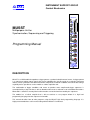
MUSST
RUN
TRIG
in
MUSST
Multipurpose Unit for
Synchronisation, Sequencing and Triggering
out A
out B
card
1
2
Programming Manual
card
3
4
card
5
6
DESCRIPTION
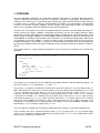
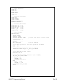
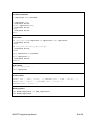
MUSST is an NIM module that produces trigger patterns synchronised with external events. A trigger pattern
is a sequence of trigger output signals that can be adapted to the specific needs of a particular experiment
and be used to synchronise the different beamline components involved. In addition, the built-in data storage
capability makes possible to use the module as a data acquisition unit.
The combination of trigger conditions and events to produce more complicated trigger sequences is
accomplished by a logic unit that is able to decode and execute a reduced set of microcoded instructions.
Microcode is stored in a memory block and instructions are fetched and executed by the sequencer.
The module has a built-in compiler that is able to translate a user program written in a high level
programming language into the sequencer microcode.
This manual describes how to write programs using the MUSST high level programming language. It is
highly recommended to use this manual along with the MUSST User Manual.
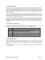
Date
25/05/2006
07/11/2007
19/10/2009
Version
1.0
1.1
2.0
Comments
First version release (PF)
Language description and examples included (PF)
Text corrections, document new organization, real program included (RH)
MUSST Programming Manual
2 of 26
CONTENTS
MANUAL ORGANIZATION
4
1. OVERVIEW
5
2. PROGRAM MANIPULATION
7
2.1. LOADING AND CLEARING PROGRAM MEMORY
2.2. PROGRAM AND LABELS
2.3. RUNNING PROGRAMS
2.4. CHECKING THE MODULE STATE
2.5. EXIT AND STOP CODES
2.6. DEBUGGING FACILITIES
7
7
8
8
8
9
3. LANGUAGE DESCRIPTION
10
3.1. EMBEDDED COMMENTS
3.2. PROGRAM BLOCKS, LABELS AND BRANCHING
3.3. CONDITIONAL EXECUTION AND FLOW CONTROL
3.4. PROGRAM VARIABLES, CONSTANTS AND ALIASES
3.5. EVENT AND ACTION MANAGEMENT
10
10
13
14
16
4. “REAL WORLD” EXAMPLE
18
4.1. OSCILLATION – MUSST PROGRAM
4.2. OSCILLATION – CONTROL SOFTWARE
18
21
APPENDIX A. MUSST PROGRAMMING LANGUAGE REFERENCE
23
MUSST Programming Manual
3 of 26
MANUAL ORGANIZATION
The MUSST Programming Manual is composed of the following sections and appendix:
Section 1 gives an overview of the programming language with simple examples.
Section 2 shows how to handle the programs, i.e., how to load them into the module, and how to run and
stop them.
Section 3 describes the main features of the programming language along with several examples.
Section 4 presents a “real world” program with the associated commands and interaction with the control
software at the ESRF.
Appendix A is the MUSST programming language reference.
The MUSST Programming Manual is the companion guide to the MUSST User Manual. Both of them are
essential to write effective MUSST programs.
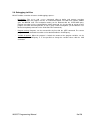
In order to facilitate the readability of this manual the following typographical conventions are used:
Font convention
Arial
Arial bold
Arial bold italic
Arial italic
Courrier italic
Courrier
Consolas
Used for
Texts
Section names, titles
Commercial parts
MUSST commands in texts
MUSST commands in examples
MUSST programs
ESRF control software macros
MUSST Programming Manual
Example
This is a text example.
5.6. Section example
Spec
?VER
CHCFG CH1 ENC
STORELIST TIMER
musst_comm()
4 of 26
1. OVERVIEW
The main application of MUSST is the generation of patterns and sequences of trigger and output signals
aimed to synchronise the different instruments and devices involved in a experiment. Those patterns or
sequences can be themselves synchronised either with the input signals fed into MUSST or with respect to
its internal timer. In order to allow the implementation of flexible and reconfigurable synchronisation
schemes, the selection of trigger conditions and the chaining and sequencing of actions are defined by
means of a user program that can be tailored to each particular application.
In general, the user program has to be first loaded into MUSST and then executed. While the program is
running and once the trigger conditions selected by the program are met, the module generates output
signals and store input signal data into its internal data memory according to the specified instructions. In the
MUSST jargon, the trigger conditions are called events, while the generation of signals or data storage are
called actions. As already mentioned, both events and actions are selected and configured by software (the
user program) but once the module is armed, the output actions are triggered from the input events by
hardware comparators. This provides a very precise synchronisation that is latency-free and is limited either
by the timing resolution of the input signals or ultimately by the internal resolution of the MUSST electronics
(20 ns).
The program below is a simple example that illustrates some of the features and the basics of the MUSST
operation:
// The internal timebase is set to 1 MHz
UNSIGNED USEC
PROG
TIMER = 0
CTSTART TIMER
FOR USEC FROM 10 TO 100 STEP 10
@TIMER = USEC
AT TIMER DO ATRIG
ENDFOR
ENDPROG
Example 1
This program is an example that can be loaded and executed in MUSST. Note that MUSST programs are
not case sensitive (USEC is equivalent to usec and Usec).
The first line is a program comment that reminds that the internal timebase is set to the default value (1
MHz) and therefore the timer units are microseconds. Inside the program block defined by the PROG and
ENDPROG statements the internal timer (TIMER) is first set to zero and then started by the CTSTART
statement. The internal timer will start counting 1 microsecond intervals as soon as the CTSTART statement
is executed. The variable USEC is made to vary up to 100 in steps of 10 by the FOR/ENDFOR loop. At every
step the timer target value (@TIMER) is then set to the value of the USEC variable and the unit is armed to
wait for the event condition and generate a pulse at the front panel Trig Out A output connector. In the
example this is achieved by the AT statement and in this simple case the event condition is defined as the
internal timer (TIMER) reaching its target value (@TIMER).
Once this program is loaded and executed, the module generates 10 pulses at 10 microsecond intervals.
In this example, the names used for the internal timer (TIMER), its target value (@TIMER) and the output
signal (ATRIG) are built-in symbols predefined in the language, while USEC is a user variable whose name
can be chosen arbitrarily (see Section 3.4).
MUSST Programming Manual
5 of 26
The next example shows how the input signal channels can be used to generate event conditions and
trigger external actions:
ALIAS PHI = CH2
// PHI is an alias for the input channel 2
PROG
CTSTOP TIMER
CTRESET TIMER
CTSTART ONEVENT TIMER
// The timer will start at next event
FOR @PHI FROM 10000 TO 20000 STEP 50
AT PHI DO NOTHING
@TIMER = $TIMER + 5
AT TIMER DO ATRIG
ENDFOR
ENDPROG
Example 2
The input channel 2 (CH2) is first renamed PHI to be used with a more meaningful name in the program
code. This is mandatory: input channels must always be renamed by means of ALIAS declarations.
In the program block the target register associated to channel 2 (@PHI) is made to go through values from
10000 to 20000 in steps of 50. For each specific value, the unit is instructed to wait for the input signal
reaching the target value and not taking any action at that time (AT PHI DO NOTHING) but generating a
pulse 5 microseconds later. This is implemented by using the fact that when an event happens, the timer
latch register ($TIMER) is always loaded with the value of the internal timer at the event occurrence. In the
example, the unit is instructed to set the timer target register to 5 microseconds after the previous event
(@TIMER = $TIMER + 5) and then wait until the new timer target is reached and produce an output pulse
at the TRIG OUT A output (AT TIMER DO ATRIG).
Another difference with respect to Example 1, is that the timer in this case is not started immediately when
the program runs and after it is set to zero (CTRESET TIMER); instead it is instructed to start only once the
first event condition is reached. This is achieved by using the ONEVENT modifier with the CTSTART
statement (CTSTART ONEVENT TIMER). Therefore, in this case, the timer will remain idle with a zero value
until channel 2 (PHI) reaches 10000 (the first target value in @PHI).
MUSST Programming Manual
6 of 26
2. PROGRAM MANIPULATION
This section describes how to manipulate MUSST programs, i.e., how to load them into the module, how to
run them, how to debug them, and how to check what the module is doing.
2.1. Loading and clearing program memory
MUSST programs are written in a high-level language and can be created and manipulated with text editors
like usual files in conventional programming languages. A program is a set of ASCII lines containing
declaration and execution statements. Programs can also include comments and empty lines in order to
improve readability. Once a program has been created with a text editor and is complete, it can be uploaded
into MUSST through any of the available communication interfaces (RS232, RS422 or GPIB). Programs are
uploaded line by line by means of the ‘+’ command. MUSST process the program lines as they are uploaded
and in case of errors generates and stores the corresponding error messages.
The actual procedure for program uploading and error checking is simplified by using appropriate software
tools to communicate with the module.
The ?LIST query can be used at any time to explore the current content of the program memory. By default
?LIST returns the currently loaded program lines but can also be used to return the list of program errors
(?LIST ERR). Program loading in MUSST is incremental; by default, new code lines are added to the
previously loaded program lines. However the uploaded code must be complete and free of errors before a
program can be executed. If the uploaded code contains errors, the program memory must be completely
cleared by the CLEAR command before the new corrected code can be reloaded.
See the MUSST User Manual for further information on the ‘+’ and CLEAR commands, and a complete
description of ?LIST options.
Even if user programs are written in a high-level language, the internal sequencer engine executes only lowlevel microcode instructions. When a new program is uploaded, the MUSST embedded just-in-time (JIT)
compiler generates the corresponding internal microcode on the fly. If a program is already running in the
sequencer at that time, the new generated microcode is temporarily stored in internal memory. Only once
the running program stops or is aborted, the new microcode is actually loaded in the sequencer engine and
is ready to be executed.
The ?LIST ASM query can be used to display the listing of the microcode produced by the JIT compiler even
though this is not really necessary in normal utilization.
2.2. Program and labels
A MUSST program file is composed of declaration statements and program blocks that can be either
programs or subroutines. The declaration statements are required to define names and types of user
variables and constants, as well as the size of data memory buffers, and must always appear before any
program block.
The number of programs and subroutines that can be loaded simultaneously in a MUSST module is only
limited by the amount of available memory and internal resources. Each program or subroutine has to be
named with a unique label. Only the main program is an exception to this rule as it can be declared with no
label. The only singularity of the main program is that it is “anonymous” and that it is the one to be executed
by default (see RUN command in the MUSST User Manual). Only one main program can be loaded at a
time, all the other programs and all the subroutines have to be identified with labels.
Labels are not only used to name programs and subroutines, they can be included in program blocks to
identify specific lines and implement conditional or unconditional program execution branches.
MUSST Programming Manual
7 of 26
2.3. Running programs
Once programs are successfully uploaded and compiled, they can be executed by the RUN command. By
default, the RUN command starts execution at the first code line of the main program, but it can also be
used to start execution of another program and/or to select different program entry point by specifying a
label of the uploaded code. However, not all the valid labels can be used as execution entry points. Labels
defined in subroutines or within flow control blocks like WHILE, FOR or IF structures cannot be used as
program entry points.
The user can interrupt program execution with the ABORT and STOP commands. ABORT resets the
sequencer and prepares the module to restart the program or to reload new code. STOP pauses the current
program but does not reinitialise the internal execution variables. A program halted by a STOP command
can be resumed by issuing the CONT command.
Note that the STOP command is different from the STOP program statement (see Section 3.2). However
both have a somehow similar effect and halt program execution. Program pausing is intended mainly for
debugging purposes but can also be used when it is convenient to interrupt temporarily program execution
in MUSST to allow the user to take some action or even a manual intervention on other equipment or
instrument.
2.4. Checking the module state
The internal state of MUSST contains useful information about the status of the module both during program
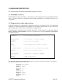
uploading and code execution. The ?STATE query returns one of the following values:
State
NOPROG
Meaning
No program loaded in the sequencer
BADPROG
IDLE
Program loaded in the module but not valid (errors or incomplete).
Program loaded in the sequencer and ready to run.
RUN
BREAK
Program running.
Program stopped at a breakpoint.
STOP
Program halted at a STOP statement, by a STOP command or after stepping.
ERROR
Program exception occurred (stack overflow, array index out of bounds).
2.5. Exit and stop codes
When a user program ends or stops, it can optionally return an exit or stop code. The code is a numeric
value specified by an expression following the corresponding EXIT or STOP statement. The expression is
evaluated at run time when the statement is executed and can be obtained by the ?RETCODE or ?STATE
queries.
Return and stop codes are useful, for instance, to identify the exit or stop points or to provide additional
information to the user.
MUSST Programming Manual
8 of 26
2.6. Debugging facilities
MUSST includes a number of features for debugging purposes:
-
Breakpoints. The BREAK and ?BREAK commands allow to define and manage execution
breakpoints. When the program reaches an enabled breakpoint, execution halts and the module
goes into BREAK state. The breakpoint number can be obtained with the ?RETCODE query.
Program execution can be resumed with the CONT command. It is also possible to start or resume
program execution instructing MUSST to skip a given number breakpoints (see the MUSST User
Manual for optional parameters in the RUN and CONT commands).
-
Program tracing. Programs can be executed line by line with the STEP command. The current
program line and microcode instruction can be obtained with the ?INSTR query.
-
Variable inspection. When the program is halted, the content of the program variables can be
obtained by the ?VAR query. It is also possible to change the variable values with the VAR
command.
MUSST Programming Manual
9 of 26
3. LANGUAGE DESCRIPTION
This section describes the MUSST programming language main features
3.1. Embedded comments
MUSST high-level code may include C++ style comments; within a program line, any text following a double
slash “//” character sequence is considered a comment and is ignored by the JIT compiler. Empty lines are
also ignored.
3.2. Program blocks, labels and branching
A MUSST program file is composed of declaration statements and program blocks. The declaration
statements are required to define names and types of user variables and constants, as well as the size of
data memory buffers, and must always appear before any program block.
The program blocks contain the actual executable code and can be either programs or subroutines. Both are
block of statements contained between PROG/ENDPROG and SUB/ENDSUB lines respectively as illustrated in
the following example:
UNSIGNED N
// User variable declaration
PROG USERPRG
N = 0
ENDPROG
// This program is labeled USERPRG
PROG
N = 1
// This program has no name (no label)
GOSUB SUBCODE
// End of program USERPRG
// This line calls the subroutine SUBCODE
ENDPROG
// End of the anonymous program
SUB SUBCODE
N += 1
ENDSUB
// Beginning of subroutine SUBCODE
// End of subroutine
Example 3
The commands below can control the program that has been just described (see the MUSST User Manual
for further information about the commands):
Command:
Command:
Answer:
Command:
Answer:
Command:
Command:
Answer:
Command:
Answer:
RUN USERPRG
?STATE
IDLE
?VAR N
0
RUN
?STATE
IDLE
?VAR N
2
MUSST Programming Manual
10 of 26
The number of programs of subroutines that can be loaded simultaneously in a MUSST module is only
limited by the amount of available memory and internal resources. Programs and subroutines have to be
identified with a unique label as it is shown in the previous example. However there is a possible exception
for this rule, and one of the programs can be declared with no label. In that case the “anonymous” program
is considered the main program and becomes the one to be executed by default (see RUN command in the
MUSST User Manual). Only one main (“anonymous”) program can be loaded at a time, all the other
programs and all the subroutines have to be identified with labels.
Labels are not only used to identify program blocks, they can be used within program blocks to implement
conditional or unconditional program execution branches. Labels declaration must appear as individual lines
including the label text followed by a colon character ‘:’ with no white spaces between them.
Branching to code labels is implemented by the GOTO statement that must be always followed by the label
name. The following example illustrates how to declare labels and how to branch to them.
PROG
…
FIRSTLABEL:
…
GOTO FIRSTLABEL
…
ENDPROG
// This declares the label position
// Put some code here
// Jump to label FIRSTLABEL
Example 4
The GOTO statement can only be used to branch to code labels within the same program block. Branching to
different program blocks can only be done by the RUN and GOSUB statements. The RUN statement starts
executing a different program and must always be followed by a program label. The GOSUB statement forces
branching to a subroutine. When the subroutine completes, the code execution returns to the calling
program and continues at the program line following the GOSUB statement.
A program ends when the execution reaches the ENDPROG line or when an EXIT statement is found. A
subroutine completes when a RETURN statement is executed or when the ENDSUB line is reached.
A program or a subroutine stops when the sequencer executes a STOP statement. To resume execution, a
CONT command should be sent to the module.
MUSST Programming Manual
11 of 26
The following example illustrates the use of the RUN, GOSUB and STOP statements:
SIGNED A
// User variable declaration
PROG
BEG:
// Anonymous “main” program
GOSUB CALC0
RUN ENDCODE
GOTO BEG
//
//
//
//
Call CALC0 subroutine.
Branch to ENDCODE program.
This line is never executed as program
ENDCODE does not return.
ENDPROG
SUB CALC0
IF (A < 0) THEN
A += 1
ENDIF
// Beginning of subroutine CALC0
RETURN
ENDSUB
// End of subroutine
PROG ENDCODE
// Additional program
STOP 77
// Program stops, returns 77 and wait
// For a CONT command to resume execution
EXIT 5
ENDPROG
// Ends program execution (return code is 5)
// End of program
Example 5
The control of this program can be carried out by the following commands sequence:
Command:
Command:
Command:
Answer:
Command:
Answer:
Command:
Command:
Answer:
Command:
Answer:
Command:
Answer:
VAR A -1
RUN
?STATE
STOP
?RETVAL
77
CONT
?STATE
IDLE
?RETVAL
5
?VAR A
0
MUSST Programming Manual
12 of 26
3.3. Conditional execution and flow control
The MUSST programming language is able to deal with conditional execution and flow control based on the
well known IF, FOR and WHILE structures.
The following example illustrates the syntax of these structures.
// -- User variables declaration
SIGNED C1
//
BOOLEAN BOO
//
UNSIGNED _AUX
//
UNSIGNED INDEX[5] = FILL(0,40) //
UNSIGNED RVAL = 0
//
//
//
//
User provides value of C1
User provides value of BOO
Variable names can begin with “_”
INDEX = {0,10,20,30,40}
RVAL = 0 when program is loaded.
Once the program is loaded and
it is executed, RVAL will always
hold the last value.
// -- Alias declaration
ALIAS THETA = CH6
// -- Main program
PROG COND
WHILE (THETA < 1000) DO
IF (BOO) THEN
IF (C1 < 0) THEN
RVAL = 1
ELSEIF ((C1 >= 0) && (C1 <= 10)) THEN
RVAL = 2
ELSE
RVAL = 3
ENDIF
ELSE
RVAL = 0
FOR _AUX IN INDEX[1:3]
// _AUX will be 10, 20 or 30
RVAL += _AUX
ENDFOR
ENDIF
ENDWHILE
EXIT RVAL
ENDPROG
Example 6
The program above can be executed by sending the following commands to MUSST:
Command:
Command:
Command:
Command:
Answer:
Command:
Answer:
Command:
Answer:
VAR C1 -1
VAR BOO 1
RUN
?STATE
RUN
?STATE
IDLE
?VAR RVAL
1
MUSST Programming Manual
13 of 26
3.4. Program variables, constants and aliases
The MUSST programming language allows the user to define variables and constants with arbitrary names.
The value of the variables can be modified both by the program itself or by the VAR command sent to the
module. The user can also read a variable value with the ?VAR query.
It is important to note that variables and constants must be explicitly declared before any program block, i.e.,
before any PROG and SUB statements.
Moreover, the user must give the input channels a meaningful alias in order to allow the program to make
reference to them. Aliases can be given to the six input channels (CH1 to CH6) and to the digital I/O bits
(IO0 to IO15).
The MUSST programming language has some reserved names that cannot be changed nor be used for
other channels. The reserved names are TIMER, IODATA and USERVAL.
TIMER is the built-in alias to the internal timer, as already mentioned in Section 1.
IODATA is the pre-defined alias for the 16-bit digital I/O bits.
USERVAL is a variable that can hold any value generated in a program. It is used for data storage purposes
when the user needs to store specific data in the MUSST internal buffer.
Example 7 shows how to declare variables and constants, and aliases to the input channels.
The STORELIST statement defines the values that MUSST should store in its internal buffer. The
parameters TIMER, IODATA, USERVAL, and OMEGA indicates the values to be stored. The values are
stored in the following order:
1.
2.
3.
4.
5.
6.
7.
8.
9.
TIMER
CH1
CH2
CH3
CH4
CH5
CH6
IODATA
USERVAL
In the Example 7, the internal buffer is filled with the following order: TIMER, OMEGA, IODATA, and USERVAL.
The statements CTSTOP, CTRESET and CTSTART are used to stop, reset and start the declared
counter/timer. In this example, the timer is stopped, reset and restarted before it is effectively used in the
program.
In this case, when the line AT TIMER DO STORE is executed, the sequencer will store the values of the
internal timer (TIMER), the 16-bit digital I/O bits (IODATA), the user variable (USERVAL), and the channel 6
(OMEGA).
In this example, the USERVAL variable holds the value of the bit IO0 (SH_OPEN) since IODATA &
BIT_MASK = IODATA & 0x1.
MUSST Programming Manual
14 of 26
// -- User variables declaration
UNSIGNED NPOINTS
UNSIGNED TDELAY = 1000
// -- Constants declaration
CONSTANT BIT_MASK = 0x1
// -ALIAS
ALIAS
ALIAS
ALIAS
Aliases
SH_OPEN
SH_CTRL
SH_TOG
OMEGA
declaration
= IO0
= IO8
= IO9
= CH6
// I0 to IO7 are inputs
// IO8 to IO15 are outputs
// CH6 can be an encoder signal
// -- Main program
PROG SHUTTER_CONTROL
NPOINTS = 0
DOACTION OUT !SH_TOG
// Reset SH_TOG bit
STORELIST TIMER IODATA USERVAL OMEGA
CTSTOP TIMER
CTRESET TIMER
CTSTART TIMER
// Stop timer
// Reset timer
// Start timer
WHILE (OMEGA < 10000) DO
USERVAL = IODATA & BIT_MASK
@TIMER = TIMER + TDELAY
AT TIMER DO STORE
NPOINTS += 1
IF (SH_OPEN) THEN
DOACTION OUT !SH_CTRL
ELSE
DOACTION OUT SH_CTRL
ENDIF
DOACTION OUT ~SH_TOG
ENDWHILE
// Define TIMER target
// Store values if target reached
// Reset SH_CTRL bit
// Set SH_CTRL bit
// Toggle SH_TOG
EXIT NPOINTS
ENDPROG
Example 7
The control of the program above can be carried out by using the following commands:
Command:
Command:
Answer:
Command:
Answer:
Command:
Answer:
Command:
Answer:
RUN SHUTTER_CONTROL
?STATE
RUN
?STATE
IDLE
?VAR NPOINTS
100
?EDAT 400 0 0
User gets 4x100 (4 values stored x 100 points) stored data (ASCII transfer)
MUSST Programming Manual
15 of 26
3.5. Event and action management
The synchronisation, sequencing and triggering capabilities of MUSST are dependent on the way the
program deals with the events that are expected and the correspondent actions to be taken by the module.
Some of the previous examples have already made use of events and actions:
In Example 1, the event source was the internal timer (TIMER) and the action to be taken was to generate
an output signal at the front panel Trig Out A connector (ATRIG).
In Example 2, the event sources were the input channel 2 (CH2, alias, PHI) and the internal timer (TIMER),
while the associated actions were, respectively, NOTHING and the output signal Trig Out A (ATRIG).
In Example 7, the event source was the internal timer (TIMER) and the associated action was to store
(STORE) the values defined by STORELIST. In addition, an action without associated event was also
present: DOACTION OUT SH_CTRL.
The MUSST programming language provides the user with some more control on the events and actions
management. For instance, the EVSOURCE statement is used to define a valid event condition, while
EVENT/DEFEVENT and ACTION/DEFACTION define different events and actions that can be selected in the
program.
Example 8 below illustrates the use of these statements.
MUSST Programming Manual
16 of 26
// -- User variables declaration
UNSIGNED MODE
UNSIGNED TARGET
// -- Alias declaration
ALIAS THETA = CH1
// -- Event declaration
EVENT E1 = ANYOF TIMER ITRIG
// -- Action declaration
ACTION A1 = ATRIG BTRIG
// -- Main program
PROG
CTSTOP TIMER
CTRESET TIMER
IF (MODE == 0) THEN
DEFEVENT TIMER
DEFACTION ATRIG
@TIMER = TARGET
CTSTART TIMER
ELSEIF (MODE == 1)
DEFEVENT THETA
EVSOURCE THETA UP
DEFACTION BTRIG
@THETA = TARGET
ELSEIF (MODE == 2)
DEFEVENT ITRIG
EVSOURCE ITRIG RISE
DEFACTION A1
ELSE
DEFEVENT E1
EVSOURCE ITRIG FALL
DEFACTION A1
@TIMER = TARGET
CTSTART TIMER
ENDIF
AT DEFEVENT DO DEFACTION
// Stop TIMER
// Reset TIMER
//
//
//
//
Set TIMER as event source
Action for this mode is ATRIG
Set TIMER target
Start TIMER
//
//
//
//
Set THETA as event source
THETA value must always increase
Action for this mode is BTRIG
Set THETA target
// Set ITRIG as event source
// Event is ITRIG rising edge
// Actions are ATRIG and BTRIG
//
//
//
//
//
Set TIMER and ITRIG as event sources
ITRIG falling edge
Actions are ATRIG and BTRIG
Set TIMER target
Start TIMER
// Wait for event and execute action
ENDPROG
Example 8
The statement EVSOURCE THETA UP defines the way the event source THETA will be evaluated by the
sequencer. The UP keyword indicates that a valid event is when THETA value is greater or equal to TARGET
(@THETA), while the counterpart DOWN keyword would indicate that a valid event is when THETA value is
smaller or equal to TARGET (@THETA). For the specific case of TIMER, a valid event is implicitly defined as
when TIMER is greater or equal to @TIMER (timer value is supposed to be always increasing).
Note that the user variable MODE defines the event and associated actions of this program. For instance,
when MODE = 2, the sequencer executes the statement AT DEFEVENT DO DEFACTION and waits for either
a falling edge of the front panel Trig In signal (ITRIG) or that the internal timer (TIMER) reaches the TARGET
value. Once one of these events is detected, the sequencer will perform the defined action A1, i.e., both
ATRIG and BTRIG.
MUSST Programming Manual
17 of 26
4. “Real world” example
The examples presented in the previous sections illustrated the main programming features of MUSST.
Even though they were not exhaustive, they covered the most common capabilities of the MUSST
programming language (see Appendix A for a complete reference).
In this section, a complete example will be presented, that is, not only the MUSST program is described but
the associated commands and its interaction with the ESRF control software are also studied.
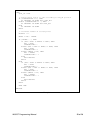
4.1. Oscillation – MUSST program
An oscillation is an experimental setup where a sample is mounted on a rotation stage driven by a motor
and an X-ray diffraction image is taken while the motor scans through a fixed angular range at constant
speed.
In addition, a shutter is placed between the sample and the X-ray source in order to expose the sample to
the X-ray beam only during the defined angular range.
MUSST was used here to synchronise the shutter state (open/close) to the rotation stage angular position.
Furthermore, MUSST has also been programmed to store a number of information related to the oscillation
in order to provide the user with a set of data for a posteriori diagnostics purposes.
The rotation stage motor position information is sent to MUSST through the input channel 1 (CH1, alias
PHI_IN). This information is usually a quadrature signal from an incremental encoder connected to this
rotation.
The control of the shutter is usually carried out by means of a digital signal available in the MUSST front
panel 25-pin Sub D connector (IO8, alias SHUT_OUT). The shutter is supposed to open when IO8 = “1”.
Optionally, an information of the actual state of the shutter can also be read by MUSST (IO0, alias
SHUT_IN), as well as two photodiodes (with respective I-V amplifiers) to monitor the X-ray beam intensity up
and downstream the shutter (CH5 and CH6, alias I0_IN and I1_IN, respectively).
For each image, the user must define the desired angular range of the rotation stage. In this program, the
angular range can be given by the variables ESH1 and ESH2 (|ESH1| > |ESH2|, always). The shutter will be
open while the rotation stage motor is in this range, or else the shutter is close.
As mentioned before, the rotation stage motor must be at constant speed during the image taking. The
variables E1 and E2 are related to the acceleration and deceleration of the motor, and it must be at constant
speed between ESH1 and ESH2. These are not critical parameters in this program, but they allow it to store
diagnostics data before the shutter opening and after its closing. Note that |E1| < |ESH1| and |E2| > |ESH2|,
and the further E1 is from ESH1, and E2 from ESH2, the more diagnostics data are stored.
The diagnostics data are stored at a regular rate given by the rotation stage motor itself. The variable DE
corresponds to the interval between two stored data.
Note that all of these 5 variables, E1, ESH1, ESH2, E2 and DE, are given in the encoder steps unit (or the
correspondent unit depending on the hardware chosen).
The CTSTART statement with the ONEVENT modifier indicates that TIMER will start when the first event
occurs. The first event in this case is when PHI_IN reaches E1 (or E2, if the PHI_IN moves from E2
towards E1). The very first data in the diagnostics data set will be PHI_IN = E1 (or E2) and TIMER = 0.
Prior to running the program, the user must set the actual position of the rotation stage by means of the
command CH CH1 <value>. This will set expected PHI_IN movement (from E1 towards E2 or from E2
towards E1) for the program.
MUSST Programming Manual
18 of 26
// -- User variables
SIGNED E1
SIGNED E2
SIGNED ESH1
SIGNED ESH2
SIGNED DE
// -- Auxiliar variables
SIGNED ETG
SIGNED NEWTG
SIGNED DETEMP
SIGNED CLOSESHUTTER
UNSIGNED NPOINTS
// -ALIAS
ALIAS
ALIAS
ALIAS
ALIAS
Aliases declaration
SHUT_IN = IO0
SHUT_OUT = IO8
PHI_IN
= CH1
I0_IN
= CH5
I1_IN
= CH6
// -- Main program
PROG OSCILLPX
CTSTOP TIMER
CTRESET TIMER
CTSTART ONEVENT TIMER
// Timer will start at first event
CLOSESHUTTER = 1
NPOINTS
= 0
OUT !SHUT_OUT
// Close shutter
// Set data pointer to the first position of buffer
EMEM 0 AT 0
// Define the values that will be stored
STORELIST TIMER PHI_IN I0_IN I1_IN IODATA
// Set PHI_IN as event source
DEFEVENT PHI_IN
// Set PHI_IN movement direction (UP or DOWN)
IF (PHI_IN < ESH1) THEN
ETG
= E1
DETEMP = DE
EVSOURCE PHI_IN UP
ELSE
ETG
= E2
DETEMP = -DE
EVSOURCE PHI_IN DOWN
ENDIF
MUSST Programming Manual
19 of 26
LOOP:
@PHI_IN = ETG
// Define which action to take according to PHI_IN position
IF (CLOSESHUTTER == 1) THEN
AT DEFEVENT DO STORE OUT !SHUT_OUT
ELSEIF (CLOSESHUTTER == 0) THEN
AT DEFEVENT DO STORE OUT SHUT_OUT
ELSE
AT DEFEVENT DO STORE
ENDIF
// Increment number of stored points
NPOINTS += 1
NEWTG = ETG + DETEMP
IF (DETEMP > 0) THEN
IF (ETG < ESH1 && NEWTG >= ESH1) THEN
ETG = ESH1
CLOSESHUTTER = 0
ELSEIF (ETG < ESH2 && NEWTG >= ESH2) THEN
ETG = ESH2
CLOSESHUTTER = 1
ELSEIF (NEWTG <= E2) THEN
ETG = NEWTG
CLOSESHUTTER = -1
ELSE
EXIT NPOINTS
ENDIF
ELSE
IF (ETG > ESH2 && NEWTG <= ESH2) THEN
ETG = ESH2
CLOSESHUTTER = 0
ELSEIF (ETG > ESH1 && NEWTG <= ESH1) THEN
ETG = ESH1
CLOSESHUTTER = 1
ELSEIF (NEWTG >= E1) THEN
ETG = NEWTG
CLOSESHUTTER = -1
ELSE
EXIT NPOINTS
ENDIF
ENDIF
GOTO LOOP
ENDPROG
Example 9
MUSST Programming Manual
20 of 26
4.2. Oscillation – control software
A set of Spec macros has been written to configure and communicate with MUSST (musst.mac) to perform
some basic operations as uploading programs, change variables values, retrieve stored data, etc.
Even though a special set of macros to control the specific case of oscillation has also been written at the
ESRF, the sequence examples below rely solely on the basic macros.
1.SPEC> musstsetup any_name 0:13
2.SPEC> f = "/users/blissadm/local/isg/musst/oscillPX.mprg"
3.SPEC> p musst_upload_program(“any_name”, f, 1)
1
4.SPEC> p musst_comm("VAR E1 100")
OK
5.SPEC> p musst_comm("VAR ESH1 200")
OK
6.SPEC> p musst_comm("VAR ESH2 300")
OK
7.SPEC> p musst_comm("VAR E2 400")
OK
8.SPEC> p musst_comm("VAR DE 10")
OK
9.SPEC> p musst_comm("CH CH1 50")
OK
10.SPEC> p musst_comm("RUN OSCILLPX")
11.SPEC> p musst_comm("?STATE")
RUN
12.SPEC> mvr phi 10
13.SPEC> p musst_comm("?STATE")
IDLE
14.SPEC> p musst_comm("?VAR NPOINTS")
200
15.SPEC> float array mdat[1000][5]
16.SPEC> p musst_getdata("any_name", 200, 5, mdat)
200
MUSST Programming Manual
21 of 26
Command lines 1 (musstsetup) informs Spec about the MUSST GPIB address, while lines 2 and 3 upload
the oscillation program (oscillPX.mprg file; note that the .mprg is not mandatory).
The oscillation parameters are sent to MUSST in lines 4 to 8, and in line 9 the input channel CH1 is loaded
with the value of the rotation stage motor position (note that this value is smaller than E1).
The program starts to run in line 10 as confirmed by the query in line 11 (MUSST state is RUN).
Line 12 indicates that the user moves the rotation stage motor. This movement covers at least the range
given by |E2 – E1|. During the movement, the shutter must open when the motor reaches ESH1 and close at
ESH2.
The state of MUSST is queried in line 13; IDLE means that the program has finished.
In line 14, the module provides the user with the number of points that it stored during the program
execution.
The stored data is retrieved in lines 15 and 16. Note that the retrieved data is stored in the array mdat. The
first dimension of this array corresponds to the maximum number of stored points, and the second one
corresponds to the number of values stored in each individual point. In this case, the program stores 5
values – see the STORELIST statement).
The user may want to control the shutter independently of the oscillation program for test purposes, for
instance. This is possible only when the program is not running. The command line 17 below shows how to
open the shutter, while line 19 shows how to close it. The state of the shutter control bit can be verified as
shown in lines 18 and 20.
17.SPEC> p musst_comm("OUT IO8")
OK
18.SPEC> p musst_comm("?OUT IO8")
1
19.SPEC> p musst_comm("OUT \!IO8")
OK
20.SPEC> p musst_comm("?OUT IO8")
0
References:
Nurizzo, D. et al. (2006). J. Synchrotron Rad. 13, 227–238
McGeehan, J. E. (2007), J. Synchrotron Rad. 14, 99–108
Leonard, G. et al. (2007), Synchrotron Radiation News, 20:3,18 – 24
MUSST Programming Manual
22 of 26
Appendix A. MUSST programming language reference
Reserved names
TIMER
IODATA
USERVAL
Events and actions
FORCE
CLREVENT
DEFEVENT <event_decl>
DEFACTION <action_decl>
STORELIST {STLIST | EVSTATUS | USERVAL | TIMER | <chan_alias>} …
EVSOURCE <ch_alias> [LATCHED] {UP | DOWN}
EVSOURCE IO [LATCHED] {LEVEL | SET | CLEAR | CHANGE}
EVSOURCE {ITRIG | RTRIG} [LATCHED] {HIGH | LOW | RISE | FALL | EDGE}
DOACTION {DEFACTION | <action_decl>}
AT [LATCHED] {DEFEVENT | <ev_decl>} DO … [WAITING statement]
AT [LATCHED] {DEFEVENT | <ev_decl>} DO {DEFACTION | <action_decl>}
[WAITING statement]
AT [LATCHED] {DEFEVENT | <ev_decl>} DO {DEFACTION | <action_decl>} WAITING
<statement block>
ENDWAITING
IFEVENT [LATCHED] {DEFEVENT | <ev_decl>} DO … [THEN statement]
IFEVENT [LATCHED] {DEFEVENT | <ev_decl>} DO {DEFACTION | <act_decl>}
[THEN statement]
IFEVENT [LATCHED] {DEFEVENT | <ev_decl>} DO {DEFACTION | <act_decl>} THEN
<statement block>
[ELSE]
<statement block>
ENDIF
EVENT and ACTION must appear before any program block: PROG and SUB statements.
EVENT <evname> = [{ALLOF | ANYOF | NONEOF | NOTALLOF}]
[!]{ITRIG | RTRIG| <alias> | <evname>} …
ACTION <actname> = NOTHING
or
ACTION <actname> = {{<actname> | ATRIG | BTRIG | RTRIG | STORE | GOSUB <subprg>} …}
[{OUT [!|~]<bitalias> …}]
MUSST Programming Manual
23 of 26
Program Statements (Must appear before any program block: PROG and SUB statements)
Memory configuration
ESIZE <buff_size> [<n_of_buffers>]
HSIZE <buff_size> [<n_of_buffers>]
Variable declaration
CONSTANT [{SIGNED | UNSIGNED}] <constant_name> = <value>
BOOLEAN [CONSTANT] <variable_name> [= <value>]
SIGNED
[CONSTANT] <variable_name> [= <value>]
UNSIGNED [CONSTANT] <variable_name> [= <value>]
{SIGNED | UNSIGNED} <array_name>[<size>] [={v0, v1, …, vn}]
[= FILL(v0, vn)]
[= BRAGG(v0, vn, f)]
ALIAS <alias_name> = {CH<n> | IO<n>}
IOMASK <constant_name> = {[IO<n> | <alias_name>]…}
Program declaration
PROG [<program_name>]
…
ENDPROG
SUB <subprog_name>
…
ENDSUB
Program exit
STOP [<stop_code>]
EXIT [<exit_code>]
RETURN
Program branch
GOSUB <subprog_name>
RUN <program_name>
<label_name>:
GOTO <label_name>
MUSST Programming Manual
24 of 26
Conditional execution
IF expression THEN statement
IF expression THEN
<statement block>
[ELSEIF expression THEN]
<statement block>
[ELSE]
<statement block>
ENDIF
Flow control
FOR <var_name> FROM expression TO expression [STEP expression]
<statement block>
ENDFOR
FOR <var_name> IN <array_name>[<range>]
<statement block>
ENDFOR
WHILE expression DO statement
WHILE expression DO
<statement block>
ENDWHILE
I/O bit control
OUT {[!|~]<bitalias> …}
BTRIG expression
Counter actions
CTSTART [ALL |
CTSTOP [ALL |
CTRESET [ALL |
CTNORESET [ALL
{{MCA | <alias>} …}] [ONEVENT] [ALL | {{MCA | <alias>} …}]
{{MCA | <alias>} …}] [ONEVENT] [ALL | {{MCA | <alias>} …}]
{<alias> …}] [ONSTORE] [ALL | {<alias> …}]
| {<alias> …}]
Memory pointers
EMEM buffn_expression [AT addr_expression]
HMEM buffn_expression
MUSST Programming Manual
25 of 26
Expression assignment
<leftvalue>
<leftvalue>
<leftvalue>
<leftvalue>
<leftvalue>
<leftvalue>
<leftvalue>
<leftvalue>
= expression
+= expression
-= expression
&= expression
|= expression
^= expression
>>= expression
<<= expression
Leftvalues are:
<var_name>
<array_name>[expression]
<channel_alias>
@<channel_alias>
<bit_alias>
TIMER
IODATA
Valid symbols in expressions are:
<var_name>
<array_name>[expression]
<channel_alias>
@<channel_alias>
<bit_alias>
TIMER
IODATA
$<channel_alias>
$<bit_alias>
$TIMER
$IODATA
<constant_name>
<iomask_name>
MUSST Programming Manual
26 of 26