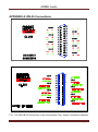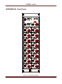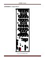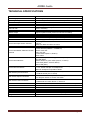
1
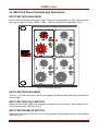
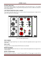
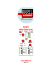
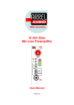
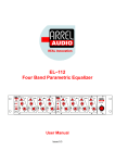
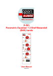
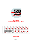
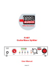
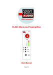
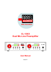
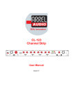
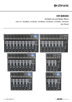
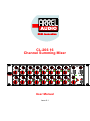
CL-266 16 Channel Summing Mixer User Manual Issue 0.1 ARREL Audio SAFETY INSTRUCTIONS WARNING Always follow the precautions listed below to avoid any possibility of serious injury or even death from electrical shock, shortcircuiting, damages, fire or other hazards. These precautions include, but are not limited to, the following: Do not expose the instrument to liquids and rain. Do not use it near water or in damp or wet conditions, or place containers on it containing liquids. If any liquid seeps turn off the power and unplug the power cord from the AC outlet. Do not put burning items, such as candles, on the unit. A burning item may fall over and cause a fire. This instrument contains no user-serviceable parts. Do not open the instrument or attempt to disassemble or modify the internal circuit. Never insert or remove an electric plug with wet hands. Check the electric plug periodically and remove any dirt or dust which may have accumulated on it. Do not place the power cord near heat sources such as heaters or radiators, and do not excessively bend or otherwise damage the cord, place heavy objects on it, or place it in a position where anyone could walk on, trip over, or roll anything over it. CAUTION Always follow the precautions listed below to avoid any possibility of serious injury or even death from electrical shock, shortcircuiting, damages, fire or other hazards. These precautions include, but are not limited to, the following: Do not connect the instrument to an electrical outlet using a multiple-connector. Doing so can result in lower sound quality, or possibly cause overheating in the outlet itself. When removing the electric plug from the instrument or an outlet, hold the plug itself and not the cord. Pulling by the cord can damage it. Remove the electric plug from the outlet when the instrument is not to be used for extended periods of time, or during electrical storms. Do not place the instrument in an unstable position where it might accidentally fall over. Before moving the instrument, remove all connected cables. When setting up the product, make sure that the AC outlet you are using is easily accessible. If some trouble or malfunction occurs, immediately turn off the power switch and disconnect the plug from the outlet. Even when the power switch is turned off, electricity is still flowing to the product at the minimum level. When you are not using the product for a long time, make sure to unplug the power cord from the wall AC outlet. Use only the stand/rack specified for the instrument. When attaching the stand or rack, use the provided screws only. Failure to do so could cause damage to the internal components or result in the instrument falling over. Information for Users on Collection and Disposal of Old Equipment This special symbol on the products, packaging, and/or accompanying documents means that used electrical and electronic products should not be mixed with general household waste. For proper treatment, recovery and recycling of old products, please take them to applicable collection points, in accordance with your national legislation and the Directives 2002/96/EC. By disposing of these products correctly, you will help to save valuable resources and prevent any potential negative effects on human health and the environment which could otherwise arise from inappropriate waste handling. For more information about collection and recycling of old products, please contact your local municipality, your waste disposal service or the point of sale where you purchased the items. [For business users in the European Union] If you wish to discard electrical and electronic equipment, please contact your dealer or supplier for further information. [Information on Disposal in other Countries outside the European Union] This symbol is only valid in the European Union. If you wish to discard these items, please contact your local authorities or dealer and ask for the correct method of disposal. CL-266 User Manual, Issue 0.1 Page 2 ARREL Audio ARREL Audio Contacts ARREL Audio Via A. Mondadori, 7 00128 Rome – Italy Tel +39 06 506 2017 Fax: +39 06 5062017 Info: [email protected] Web: www.arrel-audio.com Support: http://www.arrel-audio.com/support ARREL Audio is continuously working to the improvement of its systems and related documentation. In any case, we reserve the right to change the specifications without notice but in the respect to the current legislation. Disclaimer: The information contained in this manual has been carefully checked and we believed is accurate at the time of publication. In any case, we do not assume any responsibility for inaccuracies, errors or omissions nor any liability for any loss or damage resulting either directly or indirectly from use of the information contained in this manual. CL-266 User Manual, Issue 0.1 Page 3 ARREL Audio TABLE OF CONTENTS SAFETY INSTRUCTIONS ................................................................................................... 2 ARREL Audio Contacts ........................................................................................................ 3 TABLE OF CONTENTS ....................................................................................................... 4 INTRODUCTION ................................................................................................................. 5 Housing................................................................................................................................ 6 CL-266 Front Panel Controls and Operations ...................................................................... 7 Input section gain knob .................................................................................................... 7 Input section pan knob ..................................................................................................... 7 Input section solo button .................................................................................................. 7 Input section mute button ................................................................................................. 7 Output section .................................................................................................................. 8 Left/RIGHT master LEVEL KNOBS .................................................................................. 8 SOLO KNOB .................................................................................................................... 8 SOLO LED ....................................................................................................................... 8 MONITOR KNOB ............................................................................................................. 8 MUTE L/R BUTTONS ...................................................................................................... 8 MONO BUTTON .............................................................................................................. 9 INSERT BY PASS BUTTONS .......................................................................................... 9 PHONES JACK ................................................................................................................ 9 SEND/RETURN JACKS ................................................................................................... 9 4 x 1/4” TRS jacks for 1nsert 1 and 2 (send L-R, return L-R) .............................................. 9 CL-266 Back Panel Controls and Operations ...................................................................... 9 INPUT XLR ...................................................................................................................... 9 INPUT DB 25 (1 and 2) .................................................................................................... 9 MAIN L/R OUT ................................................................................................................. 9 MONITOR OUT ................................................................................................................ 9 SEND/RETURN 1 and 2 .................................................................................................. 9 OUTPUT DB 25............................................................................................................... 9 APPENDIX A: Connections................................................................................................ 10 APPENDIX B: Front Panel ................................................................................................. 11 APPENDIX C: Back Panel ................................................................................................. 12 TECHNICAL SPECIFICATIONS ........................................................................................ 13 CL-266 User Manual, Issue 0.1 Page 4 ARREL Audio INTRODUCTION The ARREL Audio CL-266 is a 16-channel summing mixer conceived to comply with the new demands from the digital recording technology. When used as a summing mixer, the CL-266 offers a series of distinctive features not available in any other device on the market. The signal level is controlled by a 300° potentiometer allowing a 14 dB range (12dB to +2dB) that permits a very easy level set up. It allows an easy and precise level recall even without the need for stepped level controls which are more popular but less functional. Each channel can be accessed by two different input connectors (DB25 and XLR) allowing hassle-free connections to professional DAW via a standard 8 channel multicore cable (DB25 to DB25) as well as single-channel external device insertion via XLR cables. Following the summing stage, is an insert point for connecting external units such as equalizers and compressors that can be bypassed with a front panel button. This insert connection, electronically balanced for both send and return, can be accessed either from the DB25 and XLR rear connectors or via front panel jacks. This feature is particularly useful when a main external unit (connected via the rear panel) needs to be momentarily replaced by another device. The use of the send/return front panel jacks automatically disables the corresponding rear panel connected device. The send signal on the front panel jacks is always present allowing the set-up of the levels for the outboard connected by the front panel jacks. The connection of the return cable will exclude the main outboard connected to the DB25 connector on the back panel. Therefore a unit can be connected to the front panel jacks maintaining the main insert on the back panel. Master levels are set with two separate (Left and Right) ± 6dB potentiometers. Due to the fact that Solo and Master levels can be significantly different, the monitor section has two separate and independent controls: a main master level control and a secondary solo level control (a led indicates that solo is activated). The solo mode remains active even when the channel is muted. (signal is taken after the pan control, allowing an exact stereo image positioning). Used in conjunction with mic preamplifiers, the CL-266 is the ideal mixer for engineers working in studios not equipped with a classic analog console who do not want to use digital mixers. For this reason, a different CL-266 version characterized by a level control range of -20dB/+6dB is also available. CL-266 is dedicated (due to his absolute sonic level quality) to high professional vocal recordings, classical instruments, high dynamic range instruments such as drums and percussions. ARREL Audio products are designed and manufactured in Italy. CL-266 User Manual, Issue 0.1 Page 5 ARREL Audio Housing The CL-266 is contained in a 3U rack metal box. No specific air conditioning is required for the racks, provided that there is a free flow of air through the rack from front to back and the temperature is maintained in the operating range. Consequently the racks may be stacked. CL-266 User Manual, Issue 0.1 Page 6 ARREL Audio CL-266 Front Panel Controls and Operations INPUT SECTION GAIN KNOB Rotate the level knob to change the gain. The level is controlled by a 300° potentiometer allowing a range of 14 dB (-12dB to +2dB, +6dB to -20dB version available) (Fig.1). Fig. 1 CL-266 Input Section INPUT SECTION PAN KNOB This is a -3.75 dB centre pan, with S-Law shaping to help accurate panning to extremes of left and right. INPUT SECTION SOLO BUTTON Press the solo button (LED on) to assign the channel to the solo bus. Press again to turnoff the solo function (LED off) (Fig. 1). INPUT SECTION MUTE BUTTON Press the mute button (LED on) to turn off the channel. Press again to turn-on the channel (LED off) (Fig. 1). CL-266 User Manual, Issue 0.1 Page 7 ARREL Audio OUTPUT SECTION The CL-266 output section is in the right section of the front panel (Fig. 2). The analog summation is implemented by using electronically balanced circuits to obtain the maximum level of performances. LEFT/RIGHT MASTER LEVEL KNOBS Turn the left and right knobs (Fig. 2) in order to select the required amount of gain for the main L/R output bus (± 6 dB range). Fig. 2 CL-266 Output Section SOLO KNOB Turn the SOLO gain knob (Fig. 2) in order to select the required amount of gain for the SOLO bus. SOLO LED The green LED on means that the SOLO function is activated. MONITOR KNOB Turn the MONITOR gain knob (Fig. 2) in order to select the required amount of gain for the monitor outputs. MUTE L/R BUTTONS Push the button to mute the L or the R channel (LED on). Press again to switch off the CL-266 User Manual, Issue 0.1 Page 8 ARREL Audio MUTE L/R function (LED off). MONO BUTTON Push the button to obtain a mono output (LED on). Press again to switch off the MONO function (LED off). INSERT BY PASS BUTTONS Push the button to activate the insert points (1 and 2) (LED on). Press again to bypass the insert points (LED on). PHONES JACK This 1/4” stereo TRS jack is for headphones with a minimum headphone impedance of 600Ω. SEND/RETURN JACKS 4 x 1/4” TRS jacks for insert 1 and 2 (send L-R, return L-R) CL-266 Back Panel Controls and Operations INPUT XLR The 16 XLR female connectors for the input channels are clustered ion two groups of 8. INPUT DB-25 (1 AND 2) Two DB-25 can also be used for the input channels connections. Each DB-25 can accommodate 8 input channels (Fig. 1 Top). MAIN L/R OUT XLRs for the L/R main output. MONITOR OUT XLRs for the L/R monitor output. SEND/RETURN 1 AND 2 XLRs for send/return 1 and 2. OUTPUT DB-25 The output DB-25 connector is used to simplify the output connections by a using a multicore cable. (Fig. 1 bottom) VU OUTPUT Connect a stereo TRS jack to connect a VU system. CL-266 User Manual, Issue 0.1 Page 9 ARREL Audio APPENDIX A: DB-25 Connections FIG. 1 CL-266 DB-25 Connections. Input Connections (Top), Output Connections (Bottom) CL-266 User Manual, Issue 0.1 Page 10 ARREL Audio APPENDIX B: Front Panel FIG. 3 CL-266 Front Panel CL-266 User Manual, Issue 0.1 Page 11 ARREL Audio APPENDIX C: Back Panel Fig. 4 CL-266 Back Panel CL-266 User Manual, Issue 0.1 Page 12 ARREL Audio TECHNICAL SPECIFICATIONS Number of Channels: 16 Power Supply Linear Regulator (Balanced C-Core Transformer) Operating Voltage 220V 50 Hz, (110V 60 Hz version available) Power Consumption 30 W Input Electronically balanced, Impedance > 10 KΩ Channel Gain -12 2 dB range, rotary knob continuous control (+6dB to -20dB version available) Master Output Electronically balanced Output Impedance 50Ω (minimum external load 600Ω). Master Level Level +4dBu, Max +28dBu Bandwidth 5 - 200.000 Hz -1dB, perfect square wave up to 20 KHz Distortion + Noise <0.005% ( typical 0.001 %) Front Panel Input Section Controls Gain range from -12dB to +2dB Pan Pot buttons for Mute and Solo functions Front Panel Master & Monitor Section Controls 2 Master level gain controls, range ± 6dB (MASTER L, MASTER R) 2 Insert buttons (INSERT L, INSERT R) Monitor Level Pot Solo Level Pot 2 mute buttons (Mute L, Mute R) Mono button Front Panel Indicators Input Section (each channel): yellow LED (Solo) red LED (Mute) Master Section: 2 green LEDs (Insert L, Insert R) 3 red LEDs (Mute L, Mute R, Mono) Yellow LED (Solo) Front Panel Connectors 4 x 1/4” TRS jacks for Inserts (send L-R, return L-R) 1 x 1/4” stereo TRS jack for headphones Minimum Headphone impedance 600Ω Rear Panel Input Connectors 16 x Balanced XLR female (Ch1 to Ch16) 2 x DB-25 female (Ch1 to Ch16) Rear Panel Output Connectors 4 x Balanced XLR male (MAIN, MONITOR) 1/4” TRS jack stereo VU meter connection Rear Panel Insert Connectors 2 x Balanced XLR female: Send L, Send R 2 x Balanced XLR male: Return L, Return R Rear Panel Master Connectors DB-25 female (Main L/R, Monitor L/R, Send L/R, Return L/R) Rear Panel AC mains IEC C13 16 A connector, AC mains cord with IEC Schuko 16A Rear Panel Main Switch Power On/Off switch Construction 3U 19" rack mount metal box Dimensions W 483 mm / 19”, H 133.35 mm / 1.75” (1 RU), D 225 mm / 8.86” Weight 7 kg CL-266 User Manual, Issue 0.1 Page 13