1
ArbotiX Commander
V1.3 for Rev A Boards
User Manual
Introduction
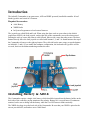
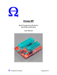
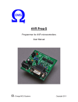
The ArbotiX Commander is an open-source, AVR and XBEE powered, hand-held controller. It has 2
thumb joysticks and a total of 10 buttons.
Required Accessories:
●
AAA Battery
●
XBEE Radio
●
In-System Programmer to load custom firmware
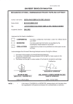
The joysticks are called Walk and Look. When using the demo code on your robot (or the default
export from NUKE), the look joystick, on the right side of the commander, moves the robot around.
Pushing the stick up causes the robot to walk forward. Side-to-side causes the robot to turn. The three
buttons directly above the look joystick are called walk buttons 1,2, and 3. A fourth button at the top of
the Commander is known as the right top button. The walk side has the same setup, except the buttons
are labeled 4,5, and 6. If you enable the southpaw configuration, the look and walk joysticks will be
reversed, however the button numbering remains the same.
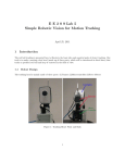
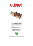
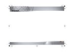
Installing Battery & XBEE
The Commander requires a single AAA battery, which should be inserted into the battery holder on the
back side of the controller, paying attention to the polarity. Battery life is several hours of continuous
runtime, but be sure to change out the battery when the User LED starts to blink erratically.
The XBEE also plugs in on the back side of the Commander. Be sure that your XBEE is paired to the
one on your ArbotiX, and both are set to 38400 baud.
Writing Code for Your ArbotiX
The robocontroller library (http://robocontroller.googlecode.com) includes a library for interfacing with
the Commander.
The Commander library can be instantiated by putting the following at the beginning of your sketch:
#include <Commander.h>
Commander command = Commander();
The library has several functions:
void begin(int baud)
Starts the library, must be called in setup(). Baud should be 38400.
int ReadMsgs()
Attempts to decode messages in the Serial0 buffer, should be
called at approximately 30hz to avoid buffer overrun. Returns >0
if a message is completely decoded (and parameters should thus
be updated).
void UseSouthPaw()
Enables the south paw configuration, swapping look and walk
joysticks.
void UseExtended()
Enables the extended mode, see the hacking section on protocol
for more details of what this does.
And several variables:
Variable
Description
signed char walkV
Vertical displacement of the walk joystick (-100 to 100)
signed char walkH
Horizontal displacement of the walk joystick (-100 to 100)
signed char lookV
Vertical displacement of the look joystick (-100 to 100)
signed char lookH
Horizontal displacement of the look joystick (-100 to 100)
unsigned char buttons
Value of the buttons, see masks below
unsigned char extra
Extra byte in the protocol payload – for user modifications.
The masks for the buttons variable are:
BUT_R1
BUT_L5
BUT_R2
BUT_L6
BUT_R3
BUT_RT
BUT_L4
BUT_LT
So, to read if the left top button was pressed, you would:
if(command.ReadMsgs() > 0){
if((command.buttons&BUT_LT) > 0){
// do something
NUKE uses a piece of code similar to:
// at the top of the file:
Commander command = Commander();
// put this in your setup() function
command.begin(38400);
// put this in the loop() function
if(command.ReadMsgs() > 0){
Xspeed = ((command.walkV));
if((command.buttons&BUT_RT) > 0)
Yspeed = (command.walkH);
else
Rspeed = -(command.walkH)/250.0;
bodyRotY = (((float)command.lookV))/250.0;
if((command.buttons&BUT_LT) > 0)
bodyRotX = ((float)command.lookH)/250.0;
else
bodyRotZ = ((float)command.lookH)/250.0;
}
Note that we must create an instance of the Commander class, in this case we call it command. Inside
our setup() function we must call command.begin(38400) to open the serial port.
This example attempts to read messages. It then sets the Xspeed (forward speed) to the vertical offset
of the Commander's walk joystick – pushing the stick up will walk forward. If the top button above the
walk stick is pressed, we strafe by setting the Yspeed, otherwise, we turn by setting the Rspeed to the
horizontal displacement of the walk joystick.
Since NUKE can compute body rotations, we use the look joystick's vertical displacement to rotate
around the Y axis (tilt). If the top button is pressed, we will rotate about the X axis (roll), otherwise, we
rotate about the Z axis (pan), the amount that of the look joystick's horizontal displacement. Since our
rotations are in radians, -100 to 100 is way too large of a range, and we need to do some conversion to
reasonable values, as shown.
Hacking
The ArbotiX Commander was meant to be hacked. It's open source, and all pin are brought out to
something. The following sections detail how to connect new accessories or modify the firmware of
your ArbotiX Commander.
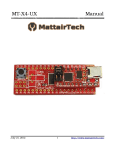
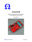
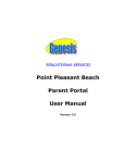
Prototyping Header
Along the side of the AVR, there is female header for prototyping. 4 of the AVR's 6 analog pins are
used to read the joysticks. The remaining two are unused, and brought out to the prototyping header.
These last two analog pins also double as an I2C connection.
Pin
Function
1
Analog 5 (PC5), unused, I2C SCL
2
Analog 4 (PC4), unused, I2C SDA
3
Analog 3 (PC3), Look Joystick Horizontal
4
Analog 2 (PC2), Look Joystick Vertical
5
Analog 1 (PC1), Walk Joystick Horizontal
6
Analog 0 (PC0), Walk Joystick Vertical
7
Ground
8
VCC
9
VCC
10
PB5, Look Button 6
11
PB4, Look Button 5
12
PB3, Look Button 4
13
PB2, User LED
14
PB1, Look Button Top
There is also a prototyping area at the top of the Commander, in between the two top buttons.
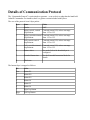
Details of Communication Protocol
The “Commander Protocol” is quite simple to generate – even on devices other than the hand held
ArbotiX Commander. For instance, there is a python version included with PyPose.
The core of the protocol is an 8-byte packet:
Byte
Name
Value
1
Header
0xFF
2
Right joystick, vertical
displacement
Centered around 128, values can range
from -125 to 125.
3
Right joystick horizontal Centered around 128, values can range
displacement
from -125 to 125.
4
Left joystick vertical
displacement
Centered around 128, values can range
from -125 to 125.
5
Left joystick horizontal
displacement
Centered around 128, values can range
from -125 to 125.
6
Button values
See masks below for how this byte is
configured
7
Extended Instruction
See the Extended Instruction Mode for
details
8
Checksum
The buttons byte is mapped as follows:
Bit
Value
Low
Button R1
2
Button R2
3
Button R3
4
Button L4
5
Button L5
6
Button L6
7
Right Top Button
High
Left Top Button
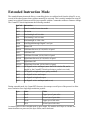
Extended Instruction Mode
The extended instruction mode allows a controlling device to read data back from the ArbotiX, or use
several of the other features that would not normally be activated. This is mainly intended for using PC
control on an ArbotiX that must still be inter-operable with the Commander without a firmware change.
The CommEXT sketch implements the following standard:
OpCode Instruction
0x00
Cancel extended instruction mode
0x08
No Action
0x10
Read Analog0 as 8-bit value
0x11
Read Analog1 as 8-bit value
0x1k
Read AnalogK as 8-bit value
0x1B
Read Digital0 through Digital7 as a byte
0x40
Motors Off
0x50-k
Left Motor Reverse, (k*10)/100% of speed
0x50
Left Motor Off
0x50+k
Left Motor Forward, (k*10)/100% of speed
0x70-k
Right Motor Reverse, (k*10)/100% of speed
0x70
Right Motor Off
0x70+k
Right Motor Forward, (k*10)/100% of speed
0x80
Set Digital0 as low and input (note: the LED is tied to D0, and is
toggled by the CommEXT sketch each time a packet is received).
0x81
Set Digital0 as high and input (pullup enabled)
0x82
Set Digital0 as low and output
0x83
Set Digital0 as high and output
0x84
Set Digital1 as low and input (and so on)
During extended mode, the CommEXT firmware also remaps several bytes of the protocol to allow
more resolution for a single high-resolution joystick:
Byte
Name
Value
2
Pan H
Upper byte of pan value.
3
Pan L
Lower byte of pan value.
4
Tilt H
Upper byte of tilt value.
5
Tilt L
Lower byte of tilt value.
A returned packet in the extended mode is quite simple. We send the 0xFF byte as a header, the
instruction that was processed, the byte of data, and a checksum.
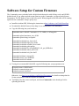
Software Setup for Custom Firmware
The Commander comes preloaded with a default sketch that works with all demo code, and NUKE's
default sketch. If you want to upload custom firmware to the Commander, you'll need an In-System
Programmer. The ISP header is next to the left joystick. When plugged in, the ISP cable will be running
upward on the commander. Setup is pretty easy:
●
Install the Arduino IDE, following the instructions at http://arduino.cc/en/Guide/HomePage
●
Download the default firmware from http://www.vanadiumlabs.com/commander
●
Copy the following into your boards.txt
commander.name=ArbotiX Commander (3.3V, 8 MHz) w/ ATmega168
commander.upload.maximum_size=16384
commander.upload.using=avrispmkii
commander.bootloader.low_fuses=0xc2
commander.bootloader.high_fuses=0xdd
commander.bootloader.extended_fuses=0x00
commander.bootloader.path=atmega
commander.bootloader.file=ATmegaBOOT_168_pro_8MHz.hex
commander.bootloader.unlock_bits=0x3F
commander.bootloader.lock_bits=0x0F
commander.build.mcu=atmega168
commander.build.f_cpu=8000000L
commander.build.core=arduino
●
If using the recommended Pololu ISP, copy the following into your programmers.txt:
avrispmkii.name=AVRISP mkII
avrispmkii.communication=serial
avrispmkii.protocol=stk500v2
Otherwise, visit http://www.arduino.cc/en/Hacking/Programmer for details on using other InSystem programmers with the Arduino environment.
●
You'll then select the correct serial port, and select Commander as the board type before
uploading the sketch.
Revision History
September 13, 2010 – V1.3 – Fix CommEXT pan/tilt byte order, add note about LED.
July 22, 2010 – V1.2 – Updated extended instruction set for actual CommEXT sketch.
February 21, 2010 – V1.1 – Added sections detailing the protocol, updates about revisions found in
RoboControllerLib 0005, including southpaw.
February 10, 2010 – V1.0 – Document Created, in sync with RoboControllerLib 0003