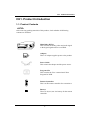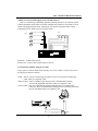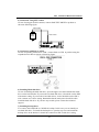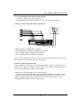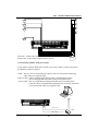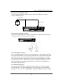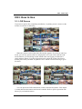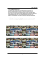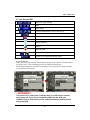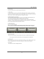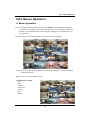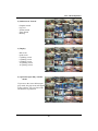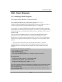
1
Thank you for using our product.
1. This is user's manual for High-end 4CH, 8CH and 16CH DVR (Digital Video
Recorder).
2. This manual contains product specification and introduction, installation guide,
operating guide and other necessary matters for easy understanding. Users should
read this user's manual carefully for proper use.
3. Contents in this manual may be changed according to the specification change and
feature improvement without any notification.
4. This user's manual shall never be copied without prior agreement and violating this
may be a reason for legal punishment on piracy.
5. If there is any incorrect or insufficient content in this user's manual, notify it to
Customer Support Center.
1
CONTENTS
Contents
CH 1. Product Introduction
1-1. Product Contents
1-2. Specifications
1-3. Product Characteristics
1-4. Name of Each Part
1-4-1. 4CH
1-4-2. 8 and 16CH
4
6
8
10
10
12
CH 2. Installation Guide and Cautions
2-1. Cautions
2-2. Product Installation
2-2-1. Power Connection
2-2-2. Connecting External Device
14
16
16
16
CH 3. How to Use
3-1. LIVE Screen
3-1-1. INFORMATION Feature
3-1-2. Power off
3-1-3. Display mode change
3-1-4. PTZ (Pan, Tilt and Zoom)
22
23
24
25
26
3-2. Search Screen
3-2-1. Graphic Search
3-2-2. Log List
3-2-3 Text In Search
3-2-4. Time Search
3-2-5. Backup
3-2-6. File Search in Play Mode
3-2-7. INFORMATION Feature in Play Mode
3-2-8. Instant Replay
29
32
33
34
35
36
37
37
38
2
CONTENTS
Contents
3-3. Setup Menu Screen
3-3-1. A/V(Audio/Video)
3-3-2. Rec(Recording)
3-3-3. Event In
3-3-4. Alarm Out
3-3-5. Storage
3-3-6. NETWORK
3-3-5. SYSTEM
39
39
41
44
47
48
50
52
CH 4. Mouse Operation
54
CH 5. Client Program
56
5-1. Installing Client Program
56
5-2. How to use Client Program
5-2-1. Initial Screen
5-2-2. Connecting the DVR
5-2-3. Initial Screen after connection
5-2-4. WATCH-live viewing
5-2-5. SEARCH-playback
5-2-6. SETUP-remote setup of DVR
60
61
63
64
65
66
71
5-3. Firmware Upgrade
76
5-4. Web browser Monitoring and Playback
78
Trouble Shooting
79
Warranty
80
3
CH 1 Product Introduction
CH1. Product Introduction
1-1. Product Contents
<4CH>
After removing packing materials of this product, check whether all following
contents are included.
UP
POWER
RECORD
LEFT
ENTER
RIGHT
PLAY
DOWN
1
2
3
4
5
6
7
8
9
0
MENU
EXIT
Main Body (DVR):
This converts the analog video and audio signal
to the digital signal and saves on HDD.
Adapter:
This 12V adapter supplies power to the product.
Power Cable:
This connect the adapter and the power source.
Program CD:
This contains the User’s manual and Client
Program for DVR.
Remote Controller:
This is an IR remote controller for convenience.
Battery:
These are 2(two) AA size battery for the remote
controller.
4
CH 1 Product Introduction
<8 and 16 CH>
After removing packing materials of this product, check whether all following
contents are included.
Main Body (DVR):
This converts the analog video and audio signal
to the digital signal and saves on HDD.
Adapter:
This 12V adapter supplies power to the product.
Power Cable:
This connect the adapter and the power source.
Program CD:
This contains the User’s manual and Client
Program for DVR.
Remote Controller:
This is an IR remote controller for convenience.
Battery:
These are 2(two) AA size battery for the remote
controller.
5
CH 1 Product Introduction
1-2. Specifications
<4CH>
Image Input/Output : NTSC / PAL
Recording Speed :
NTSC - 1~123fps(based on 360X240)
PAL - 1~103fps(based on 360X288)
Compression Method : MPEG4 Technology
Recording Time : 48~17,780 hours (160G)
Power : DC12V, 4.5A (DC adapter)
Power Consumption : 34W
External Terminal : Video Input - BNC 4CH
Video Output - BNC 1CH, S-Video 1CH, VGA 1CH(optional)
Spot Out- BNC 1CH
Loop Out - Loop Through 4CH
Audio Input - RCA 4CH
Audio Output - RCA 1CH
Sensor Input - Terminal Block 4CH (Contact, TTL)
Sensor Output - Terminal Block 4CH (Dry Contact)
LAN Communication - RJ45 Port
Serial Communication - DSUB9(RS-232C)
Terminal Block(RS485)
USB 1.1 Type A
Temperature : 5~40℃(30~110 F)
Humidity : 20%~80%(Non-condensing)
Size : 277 (W) × 315 (D) × 80 (H) mm
Weight : Lighter than 4.5Kg(Supplements and Packing Materials Excluded)
Supplements : Adapter 1
Power Cable 1
Program CD 1
Remote Controller 1
Battery 2
6
CH 1 Product Introduction
<8CH / 16CH>
Image Input/Output : NTSC / PAL
Recording Speed :
NTSC -1~127(8ch), 1~135fps(16ch) : based on 360X240
PAL - 1~107(8ch), 1~115fps(16ch) : based on 360X288
Compression Method : MPEG4 Technology
Recording Time : 44~17,780 hours (160G, 16ch)
47~17,780 hours (160G, 8ch)
Power : DC12V, 8A (DC adapter)
Power Consumption : 96W
External Terminal : Video Input - BNC 8CH / 16CH
Video Output - BNC 1CH, S-Video 1CH, VGA 1CH
Spot Out- BNC 1CH
Loop Out - Loop Through 8CH / 16CH
Audio Input - RCA 4CH
Audio Output - RCA 1CH
Sensor Input - Terminal Block 8CH (Contact, TTL) / 16CH
(Contact, TTL)
Sensor Output - Terminal Block 8CH (Dry Contact 4CH) /
12CH (Dry Contact 4CH)
LAN Communication - RJ45 Port
Serial Communication - DSUB9(RS-232C)
Terminal Block(RS485)
USB 1.1 Type A
Temperature : 5~40℃(30~110 F)
Humidity : 20%~80%(Non-condensing)
Size : 430 (W) × 420 (D) × 88 (H) mm
Weight : Lighter than 5.5Kg(Supplements and Packing Materials Excluded)
Supplements : Adapter 1
Power Cable 1
Program CD 1
Remote Controller 1
Battery 2
7
CH 1 Product Introduction
1-3. Product Characteristics
1) High quality picture
This enables recording and playing high quality digital image based on MPEG4
compression method.
2) High reliability
With Embedded hardware and software design, this maintains higher product
reliability compared to common PC type products.
3) Simple usage
This allows users to use it conveniently by placing control buttons similar to existing
ones on VCR, and users can easily learn the usage.
4) Triplex System
Triplex System allows recording, backup, networking and playback simultaneously.
5) Selectable recording setup
For recording methods, users can select the frame rate, resolution and video quality
individually in order to be appropriate for user's environment.
6) Remote monitoring
With using exclusive line or Internet network, you can search or monitor recorded
images remotely by installing exclusive client program on PC.
7) Backup
You can backup with USB, CD-RW and DVD-RW.
8) Audio recording
You can record four sound inputs simultaneously. Moreover, you can listen to the
sound in search and live monitoring and play mode.
9) Various recording methods
This provides convenient use with manual recording, recording by dates and days,
hourly schedule recording, sensor and motion detection event recording and others to
enable unmanned monitoring.
10) Various total monitoring features
You can use overall and economical security system through various sensor inputs
and contact output control.
11) Display information in easy-to-understand information method
This enhanced convenience of user by displaying information (date, time, recording
method, recording frame number, HDD capacity and others) in monitoring, recording
and playing mode in easy-to-understand way.
8
CH 1 Product Introduction
12) Spot monitoring
Spot out can be enable to monitor sequentially in other place.
13) P/T/Z control
By built in RS485, various P/T/Z cameras can be used.
14) Individual resolution setting
You can record in each channel by choosing 360X240, 720X240 and 720X480
individually.
15) Separate video transmission engine
DVR can send 60 fps (based on CIF) regardless of the local recording and viewing
setup regardless with recording setup.
16) Web browser support
You can monitor and playback the video and control the PTZ camera by internet
explorer.
17) Built in S.M.A.R.T.
You can automatically check the health of the hard disk drives.
18) Text inserter
You can operate with the POS and ATM.
19) Mirroring
If you install more than two HDDs, you can use the second HDD for backup for
maximum fault tolerance.
20) Language pack
Basically DVR has 5 language set, furthermore you can choose the language set if
you want.
9
CH 1 Product Introduction
1-4. Name of Each Part
1-4-1. 4CH
[Front Panel]
1 . Control Buttons
3 . Menu and Arrow Keys
Status Lamps
2.
1. Control Button : Record, Search, Lock feature.
(※ In menu and password setting, it is automatically converted to number buttons)
No.
Display
1
Backup
2
REW
3
PLAY
4
Live mode
Search Mode
Backup
Menu setting
No.”1”
Rewind
No.”2”
playback
No.”3”
FF
Fast Forward
No.”4”
5
STOP
Stop/
No.”5”
6
SLOW
Slow playback
No.”6”
7
STILL
Pause/ Step
No.”7”
8
INFO
9
LOCK
System Lock
0
PTZ
PTZ
Search
Instant Replay
Information
Protect File
No.”8”
No.”9”
No.”0”
2. Status lamps
POWER : Green. Power indicator.
RECORD : Red. Indicate the recording.
NETWORK : Green. Lit on connecting the network
3. MENU and ARROW Keys
This button is used to change settings for the product in MENU Mode or
used in Search Mode or turn it on.
※ For more details, refer to [CH 3. How to Use]
10
CH 1 Product Introduction
[Rear Panel]
14. VIDEO IN
12. RS485
13. SENSOR IN
SENSOR IN
11. SENSOR OUT
15. VGA
9. LAN
RS 485
AUDIO IN
SERIAL
DC12
8. LOOP OUT
6. NT-PAL
7. VIDEO OUT
4. AUDIO OUT
5. S-VIDEO
10. AUDIO IN
16
. USB
3. SERIAL 1. DC12V
2. FAN
1. DC Power : DC12V 4.5A
2. Cooling Fan
3. Serial Port: This is Serial communication(RS-232C) cable connection terminal.
4. Audio Out: RCA audio out terminal.
5. S-Video Out : Output for S-Video monitor. Normally you can get clearer image
than BNC.
6. NTSC/PAL select switch : Choose the proper position.
7. Video Out : For main monitor.
8. Loop Out : This sends the images from the cameras the other devices.
9. LAN Port: This is LAN cable connection terminal.
10. Audio In: RCA audio in terminals. You can record four channels at the same
time.
11. Sensor out : This terminal blocks connect external electric devices to the product
( Warning Lamp and others).
12. RS485 port : For control the pan and tile cameras. Make sure that the polarity.
13. Sensor In : This terminal connects external sensor to the product.
14. Video In: This receives images from cameras and sends them to monitors.
15. VGA port: video output for VGA display
16. USB ports : This port is for USB device.
※ For more details, refer to [CH 2. Installation Method and Cautions].
11
CH 1 Product Introduction
1-4-2. 8 and 16CH
[Front Panel]
1. Number buttons
4. USB port
5. Backup device
2. EJECT
6. Function key
3. Playback button
7. Enter and arrow key
1. Number buttons : If you push this button, it will be changed to full screen in live
viewing or playback
(※ In menu and password setting, it is automatically converted to number buttons)
2. EJECT : It will open or close the backup drive such as CD-RW or DVD.
3. Playback buttons : It will be used on playback. If you push these buttons in live
mode, it will be automatically changed to the Instant Play mode. ‘Stop’ button
changes from the play mode to the live mode.
4. USB ports : These USB ports are for mouse and USB devices. You should
connect correctly the USB devices and mouse as picture directed.
5. Backup device : You can use the versatile backup devices such as CD-RW and
DVD-RW.
6. Function keys
1) Search : It will change to the playback mode from the live mode.
2) Backup : It will move to the backup screen from the live or play mode.
3) PTZ : It will change to the pan, tilt and zoom control mode from the live mode.
4) MENU : It will move to the setup screen from the live mode.
5) DISPLAY : It will change the screen splitting sequentially from 1, 4, 6, 9, 13 and
16. It can be adapted both live and play mode.
6) SWITCHING : It will change to switching mode except 16 splitting.
7) INFO : It will turn it on and off the GUI and OSD sequentially.
8) EXIT(LOCK) : If you want move to the upper menu or exit without saving, push
this button. On playback, it will disappear the search list for the better
viewing. On live viewing, it performs the system lock.
7. ARROW, ENTER : This button is used to change settings for the product in
MENU Mode or used in Search Mode.
8. Status LED
POWER : Blue. Power indicator.
RECORD : Red. It will be lit on while recording.
NETWORK : Green. It will be lit on while connecting the network.
ALARM : Red. It will be lit on when the events happen.
※ For more details, refer to [CH 3. How to Use]
12
8. LED
CH 1 Product Introduction
[Rear Panel]
3. SENSOR, ALARM
6. RS 485
1. VIDEO IN, LOOP
4. Video out
2. Power switch
5. Audio In/Out
7. RS 232
8. NTSC/PAL switch
9. LAN
10. Power adapter
1. VIDEO IN : This receives images from cameras and sends them to monitors.
LOOP : This sends the images from the cameras to the other devices.
2. POWER : This turn it on and off the main power.
3. SENSOR IN : This terminal connects external sensor to the product.
ALARM OUT : This terminal blocks connect external electric devices to the
product ( Warning Lamp and others). The first 8 terminals are related with dry
contacts (4 relays).
4. VIDEO OUT : There are four kinds of video out such as composite, spot, SVIDEO, and analog RGB(VGA).
5. AUDIO IN : RCA audio in terminals.
You can record four channels at the same time.
AUDIO OUT : RCA audio out terminal.
6. RS485 port : For control the pan and tile cameras. Make sure that the polarity.
7. SERIAL : This is Serial communication(RS232C) cable connection terminal.
8. NTSC/PAL select switch : Choose the proper position along your video format.
9. LAN Port: This is LAN cable connection terminal.
10. DC Power : DC12V 8A.
※ For more details, refer to [CH 2. Installation Method and Cautions].
13
CH 2 Installation Method and Cautions
CH2. Installation Method and Cautions
2-1. Cautions
- Avoid installing the product where there are direct rays or it is hot by locating near
from heat generator. (May cause fire)
- Do not put vase, flowerpot, cup, cosmetics, drug, and anything the contain water on
product. (May cause fire or electric shock, and it may injure people by falling)
- Do not insert or drop any metal object (coin, hair pin) or flammable object (match,
paper) into air hole. (May cause fire or electric shock)
- Do not put any heavy object on it. (May injure people by being fell or destroyed.)
- Put power plug surely not to be moved. (If not, this may cause fire.)
- Unplug power plug and antenna when there are thunders and lightening. (May
cause fire.)
- For cleaning the product, wipe surface with dry towel. Using chemical agent or
cleaner may change the color and unpeel paint. Do not put several plugs at same
time. (May cause electric shock.) If there is smoke or strange smell, stop operation. In
this case, turn the power off and unplug it, and then contact our service center. (If you
keep using it, this may cause fire or electric shock.)
- Do not unplug by pulling cord. (If cord is damaged, it may cause fire or electric
shock.)
- Do not plug or unplug with wet hands. (May cause electric shock.)
- Keep the power cord untwisted. (May cause fire or electric shock.)
- Use proper adapter. (Using too much electric power may cause fire or electric
shock.)
- Do not install it at where exposed to rain and wind and water drop. (May cause fire,
electric shock and transformation.)
- Keep away from fire. (May cause fire.)
-Do not disassemble or remodel on your own. (May cause malfunction or electric
shock.)
- Do not put next to flammable materials like flammable spray. (May cause fire.)
- Do not install it at a place with too much dirt. (May cause fire.)
- Do not install it on unstable places like shaking table and inclined place or shaking
place. (May injure users by falling down or being upside down.)
- Do not put an heavy object on power cord or avoid it from being pushed by the
device. (May cause fire or electric shock.)
- In case of using extension cord, do not use several devices at same time. (May
cause fire with abnormal heating of extension.)
- When there are dirt on power plug pin or power outlet, clean it nicely. (May cause
fire.)
14
CH 2 Installation Method and Cautions
-Do not damage on power cord or plug, and bend or twist or pull too much, and put it
between other objects or heat. If power outlet insertion part is not tight, do not use it.
(May cause fire or electric shock.)
-Do not drop or give a shock to the product. (May injure people or cause malfunction.)
- Do not touch power adaptor or signal controller. (May cause electric shock.)
- Do not put any object too close to block cooling fan. (May cause fire.)
- In case of exchanging batteries with improper type, there might be danger of
explosion.
- For used batteries, throw away separately from other garbage.
- When you take out batteries, avoid children from eating them by mistake. Keep them
away from children. (If a child ate them, contact a doctor right away.)
Note :
This equipment has been tested and found to comply with the limits for a Class A
digital device, pursuant to part 15 of the FCC Rules. These limits are designed to
provide reasonable protection against harmful interference when the equipment is
operated in a commercial environment. This equipment generates, uses and can
radiate radio frequency energy and, if not installed and used in accordance with the
instruction manual, may cause harmful interference to radio communications.
Operation of this equipment in a residential area is likely to cause harmful
interference in which case the user will be required to correct the interference at his
own expense. Changes or modifications to this equipment may cause harmful
interference unless the modifications are expressly approved in the instruction
manual. The user could lose the authority to operate this equipment if an
unauthorized change or modification is made.
This device complies with the part 15 of the FCC Rules. Operation is subject to the
following two conditions : (1) this device may not cause harmful interference, and (2)
this device must accept any interference received, including interference that may
cause undesired operations.
FCC Warning :
This equipment may generate or use radio frequency energy. Changes or
modifications to this equipment may cause harmful interference unless the
modifications are expressly approved in the instruction manual. The user could lose
the authority to operate this equipment if an unauthorized change or modification is
made.
CE Warning : This is a Class A product. In a domestic environment this may cause
radio interference in which case the user may be required to take adequate measures.
This product has obtained EMI registration.
15
CH 2 Installation Method and Cautions
2-2 Product Installation
This product may be composed of camera and monitor in default, and additionally
the sensor, microphone, speaker and PC for network can be connected if necessary.
2-2-1. Power Connection
1) Connect adapter cable to power connection terminal at rear side.
2) Input AC power to the adapter. (free voltage from 100V to 240V, 50/60Hz)
※ You must operate it at the rated voltage instructed on the user's manual. In case
power higher than the rated voltage is supplied, it may cause damages on product.
2-2-2. Connecting External Device ( 4CH)
※ Connect it when power of the product is off.
※ Read through user's manual for the device you are connecting carefully.
1) How to Connect External Video/Audio Device
MONITOR Rear
CAMERA
MIC
VIDEO
IN
OUT
AUDIO
IN
OUT
Connect cameras to VIDEO IN by channels.
Connect microphone (AMP) to AUDIO IN by channels.
Connect VIDEO OUT to VIDEO IN of monitor.
Connect AUDIO OUT to AUDIO IN of monitor.
For Loop Out terminal at rear side, you can use it by connecting to the other external
device such as matrix which needs the camera input.
2) How to connect external sensor
Sensor terminal is composed of 4 input channels and 4 output channels. As
shown at below, if sensor output is TTL signal, connect SIGNAL line to left and
GND line to right by input channels.
16
CH 2 Installation Method and Cautions
*What are N/O (Normal Open), N/C (Normal Close)?
This is a terminology explaining operation method of Sensor. N/O Sensor is that
contact maintains Open status in normal condition and contact is converted to Close
status with beginning operation. Oppositely, N/C Sensor operates while contact
maintaining Close status converts to Open status.
SIREN
SENSOR
-
+
POWER
Sensor In : Connect the sensors.
Sensor Out : Connect the external electric devices.
3) Connecting with PC using LAN cable
If you want to connect DVR to PC directly, use Cross Cable(1), and if you want to
use HUB, use Direct Cable(2).
*Hub : This is a device connecting one office to devices located near with using
cable when you organize LAN
*Direct Cable : This is standard UTP cable used for communication among
devices through Hub and others when you organize LAN
*Cross Cable : This is a cable that has changed internal array of standard UTP
Cable for direct communication among devices not using connection
devices like Hub when you organize LAN
PC
① Cross Cable
HUB
② Direct Cable
17
CH 2 Installation Method and Cautions
4) Connection Using PTZ camera
In case of using pan and tilt cameras, connect PAN/TILT DRIVE to product as
shown at following figure.
VIDEO CABLE
SPEED
DOME
RS485 CABLE
5) Connection with POS or ATM
In case of operating with POS or ATM , connect POS or ATM to product using the
expanded serial cable as shown at following figure.
.
.
SENSOR IN
RS
485
VIDEO IN
SENSOR OUT
VIDEO OUT
AUDIO IN
LAN
S-VIDEO
LOOP OUT
NT
PALAUDIO OUT
SERIAL
DC
1V
2
Extended Serial Cable
6) Installing Hard disk drive
In case of installing the hard disk drive, open the upper case and install the hard disk
drive on the hard bracket. If you use the one hard disk drive, it should be set the IDE1
with master setting. If you use the 2 hard disk drives, it also should be set the IDE1
with 1 master and 1 slave setting. Remember that the main power should be off to
install the hard disk drive. If you have any trouble, please contact the technical
support.
7) Installing backup drive
You can use the DVD-RW or CD-RW for backup. In this case you can install just
one hard disk drive. To install the backup drive, open the top cover and install the
backup drive on the bracket. It should be connected to IDE 2 with slave setting.
18
CH 2 Installation Method and Cautions
2-1-3. Connecting External Device(8 and 16 CH)
※ Connect it when power of the product is off.
※ Read through user's manual for the device you are connecting carefully.
1) How to Connect External Video/Audio Device
MONITOR Rear
CAMERA
MIC
VIDEO
IN
OUT
AUDIO
IN
OUT
.....
Connect cameras to VIDEO IN by channels.
Connect microphone (AMP) to AUDIO IN by channels.
Connect VIDEO OUT to VIDEO IN of monitor.
Connect AUDIO OUT to AUDIO IN of monitor.
For Loop Out terminal at rear side, you can use it by connecting to the other external
device such as matrix which needs the camera input.
2) How to connect external sensor
Sensor terminal is composed of 16 input channels and 12 output ( 4 relays, 8 TTLs) c
hannels. As it shown as it below, if sensor output is TTL signal, connect SIGNAL li
ne to left and GND line to right by input channels.
*What are N/O (Normal Open), N/C (Normal Close)?
This is a terminology explaining operation method of Sensor. N/O Sensor is that
contact maintains Open status in normal condition and contact is converted to Close
status with beginning operation. Oppositely, N/C Sensor operates while contact
maintaining Close status converts to Open status.
19
CH 2 Installation Method and Cautions
SENSOR
SIREN
.....
-
Sensor In : Connect the sensors.
Sensor Out : Connect the external electric devices.
+
POWER
3) Connecting with PC using LAN cable
If you want to connect DVR to PC directly, use Cross Cable(1), and if you want to
use HUB, use Direct Cable(2).
*Hub : This is a device connecting one office to devices located near with using
cable when you organize LAN
*Direct Cable : This is standard UTP cable used for communication among
devices through Hub and others when you organize LAN
*Cross Cable : This is a cable that has changed internal array of standard UTP
Cable for direct communication among devices not using connection
devices like Hub when you organize LAN
PC
① Cross Cable
HUB
② Direct Cable
20
CH 2 Installation Method and Cautions
4) Connection Using PTZ camera
In case of using pan and tilt cameras, connect PAN/TILT DRIVE to product as
shown at following figure.
VIDEO CABLE
SPEED
DOME
RS485 CABLE
5) Connection with POS or ATM
In case of operating with POS or ATM , connect POS or ATM to product using the
expanded serial cable as shown at following figure.
Extended Serial Cable
6) Installing Hard disk drive
In case of installing the hard disk drive, open the upper case and install the hard disk
drive on the hard bracket. If you use the one hard disk drive, it should be set the IDE1
with master setting. If you use the 2 hard disk drives, it also should be set the IDE1
with 1 master and 1 slave setting. If you use the 3rd and 4th hard disk drive, it should
be connected with the secondary master and slave setting. Remember that the main
power should be off to install the hard disk drive. If you have any trouble, please
contact the technical support.
7) Installing backup drive
You can use the DVD-RW or CD-RW for backup. In this case you can install just
one hard disk drive. To install the backup drive, open the top cover and install the
backup drive on the bracket. It SHOULD be connected to IDE 2 with slave setting.
21
CH 3 How to Use
CH3. How to Use
3-1. LIVE Screen
If you turn on power after completing installation, 16 splitting screen is shown on the
monitor in real time as following.
※ When the system is locked, the Select ID window appears. If you log in with User
mode, you can only operate with live and playback. So if you want to operate with
whole function, you should log in with Admin mode. On logging, the Password
check window appears. Type the right password to unlock the system. The factory
default password is just blank. So push the ‘enter’ button at first DVR using to go to
the menu.
※ You can operate the DVR with buttons, remote controller and mouse. This chapter
is written based on the buttons and remote controller. Refer to [CH4 Operation with
Mouse] if you install the mouse.
22
CH 3 How to Use
3-1-1. INFORMATION Feature
This feature shows current settings of product through GUI (Graphic User
Interface) and INFO button at front side is used for this feature. When you
turn on power, this will show current date and time, System Lock Setting, HDD
usage, Video Loss Check, Sensor ON/OFF, Motion Detection Check, Recording Stat
us and Schedule Feature Usage. As you push INFO button once more, GUI
disappear->OSD disappear->GUI appear->OSD appear will happen sequentially.
※ GUI (Graphic User Interface): displaying current status on monitor as images
※ OSD (On Screen Display): displaying current status on monitor as character
23
CH 3 How to Use
▶ Live Screen GUI
Date (e.g.: yyyy/ mm/dd)
time
HDD usage
/
/
/
Lock up/ Administrator Log in/ User Log in
Scheduler OFF/ON
Video Loss
Sensor On/Off
Motion detection
Text In
Recording ON
/
/
Channel switching OFF/ON
Sound On and selected channel / Mute
3-1-2. Power off
When you turn it off, push the ‘Menu’ button and go to the ‘System’ and then choose
the ‘Power Off’ . After confirming power off, DVR will shut down.
Please should follow the procedure on turning it off. It is possible to make a trouble
not to follow the instruction.
• WARNING!
This power off is soft power. It means there is a still electric current
after power off. If you try to change the HDD from the DVR, you
SHOULD Turn it off the main power switch behind the product before
changing HDD.
24
CH 3 How to Use
3-1-3. Display mode change
You can change the display mode using the ‘Display’ button in front of the DVR. If
you simply enlarge certain channel to the full screen, use the 1~10+ buttons. From 1
to 10, push the related button and over 10, use the 10+ and 1~6 buttons sequentially.
As you push the ‘Display’ button, the screen changes sequentially from 1, 4, 6, 8, 9,
13 and 16 splitting mode.
Use the up , down key to change to the different channel set in the splitting mode.
If you push the ‘Switching’ button, it will be changed to automatic switching mode.
25
CH 3 How to Use
3-1-4. PTZ (Pan, Tilt and Zoom)
It is possible to control the pan and tilt camera by itself. Push the ‘PTZ’ button to
enter the PTZ mode. For Menu setting, you can set it by pushing button as displayed
at bottom of window.
1) You can set the direction of camera by using the arrow buttons.
2) Setup : If you push Menu button in PTZ Menu, camera setup window will appear.
3) Zoom In/Out : You can zoom in with #1 button and zoom out with #2 button.
4) Focus In/Out : You can adjust the focus with #3 and #4 buttons.
5) Iris In/Out : You can adjust the iris with #5 and #6 buttons.
6) Pattern : This DVR can support the pattern if the camera has this function.
- Start(#7) : This sets the pattern start.
- Stop(#8) : This sets the pattern stop.
- Run(#9) : This starts to run pattern.
7) Preset : You can toggle between the PTZ window and Preset window using
‘Enter’ button.
- Direct Call(#1~6) : You can go directly to the position 1 to 6.
- Call(#7) : You can go the other position using this button.
- Set(#8) : You can set the preset position up to 32.
- Clear(#9) : This will clear the preset position information.
- Clear All(#0) : This will clear the preset position information.
- Tour(Menu button) : If you push this button, the camera moves to the position
sequentially. To stop the tour, press the tour button once again.
26
CH 3 How to Use
8) Setup : If you push the ‘MENU’ button on PTZ window, the camera setup window
will appear.
27
CH 3 How to Use
Driver: Choose Driver to be suitable for PAN/TILT Camera manufacturer.
You have to set Comport value according to the connected camera.
BitRate
Parity
DataBit
Stop
PELCO D type
9600~2400
NONE
8
1
PELCO P type
2400
NONE
8
1
PANASONIC
2400~19200
NONE
8
1
ORIENTAL
2400(Fixed)
NONE
8
1
LPT-A100L
9600(Fixed)
NONE
8
1
LG-SD110
2400~19200
NONE
8
1
Function: This is a value setting camera moving speed. You can select
within 1~7. As this value gets higher, speed gets faster. You may
not be able to change camera speed according to camera kinds.
- PAN Speed: This is Left/Right Camera moving speed.
- Tilt Speed: This is Up/Down Camera moving speed.
* Operational Feature by Cameras
PELCO-D
PELCO P
Panasonic
Oriental
LPT-A100L
LG-SD110
Focus-ctrl
O
O
O
O
O
O
Zoom-ctrl
O
O
O
O
O
O
Iris-ctrl
O
O
O
O
O
O
Patrol-ctrl
O
O
O
O
X
X
Autopan(on/off)
X
O
O
O
O
O
AutoPan(P1,P2)
X
O
O
X(Hardware)
O
O
Pan-speed ctrl
O
O
O
X
X
O
Tilt-speed ctrl
O
O
O
X
X
O
Autopan-speed
X
O
O
X
X
O
* For connection of PAN/TILT Camera Receiver part, refer to user's manual of the
related PAN/TILT Camera.
28
CH 3 How to Use
3-2. Search Screen
▶ Play Screen GUI (4ch)
Play : Forward normal speed
Playback : Backward normal speed
FF (Fast Forward): FF×2, 4, 8, 16, 32, 64 times faster
FB (Fast Backward): FB×2, 4, 8, 16, 32, 64 times faster
SF (Slow Forward):SFx1/2, SFx1/4
SB (Slow Bacward):SBx1/2, SBx1/4
STILL (Pause)
Frame advance : use the right and left key OR ‘STILL(#7)’
▶ Various Search Features (4ch)
For search feature, you can perform searching easier and faster with using those buttons
located at front side of the product.
1) Go to the ‘Backup’ directly.
2) Play images backward fast (Every time you push, it is changed to 2, 4, 8, 16,64
times faster) If you push PLAY Button, it returns to real time playing.
3) Play recorded images in real time. If you push PLAY Button again while playing,
playing screen stops and List window is appeared.
4) Play images faster. (Every time you push, it is changed to 2,4,8,16,64 times faster)
If you push PLAY Button, it returns to real time playing.
5) Stops playing and returns to LIVE Screen.
6) Play images slowly. (Every time you push, it is changed to 1/2,1/4 times faster) If
you are in forward direction, it changes the speed to slow forward and vice versa.
7) This pause images being played and it returns to real time playing if you push Play
Button again.
8) This displays image information on screen and turn it on the GUI and OSD.
9) If you push this button on the chosen file on the Log List, it prevents from
removing while HDD overwrite.
29
CH 3 How to Use
▶ Play Screen GUI (8 and 16 ch)
Play : Forward normal speed
Playback : Backward normal speed
FF (Fast Forward): FF×2, 4, 8, 16, 32, 64 times faster
FB (Fast Backward): FB×2, 4, 8, 16, 32, 64 times faster
SF (Slow Forward):SFx1/2, SFx1/4
SB (Slow Bacward):SBx1/2, SBx1/4
STILL (Pause)
Frame advance : use the right and left key OR ‘STILL’
▶ Various Search Features (8 and 16 ch)
For search feature, you can perform searching easier and faster with using those
buttons located at front side of the product.
2)PLAY
1)RF
4)SLOW
3)RF
6)STOP
5)STILL
1) Play images backward fast (Every time you push, it is changed to 2, 4, 8, 16,64
times faster) If you push PLAY Button, it returns to normal playback.
2) Play recorded images. If you push PLAY Button again while playing, playing
screen stops and List window is appeared.
3) Play images faster. (Every time you push, it is changed to 2,4,8,16,64 times faster)
If you push PLAY Button, it returns to real time playing.
4) Play images slowly. (Every time you push, it is changed to 1/2,1/4 times faster) If
you are in forward direction, it changes the speed to slow forward and vice versa.
5) This pause images being played and if you push Play Button again it returns to
normal playback.
6) Stops playing and returns to LIVE Screen.
30
CH 3 How to Use
For searching the recorded files, push ‘Search’ button in front of DVR. You will see
following search window.
1) Graphic Search
You can search the recorded files graphically using calendar.
2) Log List
This shows a list of files and events (Sensor, Motion Detection, System and Text
in) log.
3) Text-in Search
You can search the transaction data and corresponding video recorded through
Serial port.
4) Time Search
Input time you want to search directly for searching.
5) Backup
You can backup to the CD, DVD and USB memory by time criteria.
31
CH 3 How to Use
3-2-1. Graphic Search
This displays all recorded images graphically.
After choosing the ‘Graphic Search',
you can see the calendar at first.
Use the arrow keys, go to the
wanted date which are lit in
white.(figure1) Then pushing the
‘Enter’ button, you can see the bar
graph from 0 to 24 hour below the
date list.(figure2)
figure1
Sky blue bar means that there is a
recorded file at that time. Use the
arrow key to go to the wanted time.
If you push the ‘Zoom In' button,
you can zoom in the time bar for
the fine searching. After that, push
Enter button and it starts playback
(figure3).
On playback, If you push the 'Exit'
button on playback, you can move
to the search screen. If you push
the 'Stop' button, the screen goes to
the live screen.
figure2
You can also change the display
mode using ‘Display’ button.
figure3
32
CH 3 How to Use
3-2-2. Log List
After choosing the ‘Log List', you
can see the date at first.
Use the arrow keys, go to the
wanted date, which are lit in sky
blue (figure1).
In this search mode, you can search
the File and Event List which
include event, record, and system
log. And also you can choose the
specific log such as file, sensor,
motion detection, video loss and
system by using the arrow key
(figure2).
figure1
Moreover Event regarding to video,
you can play directly.
figure2
33
CH 3 How to Use
3-2-3. Text In Search
After choosing the ‘Text In Search', you can see the search criterion at first. Use the
arrow keys, enter the wanted date, time, channel and keyword using the number keys
on the front.
And you can use the virtual keyboard to enter the keyword. To appear the virtual
keyboard, use the ‘Enter’ key. After entering the keyword, push ‘Menu’ button to
exit the virtual keyboard and push ‘Start’ button to search.
You can see the date list including the keyword and time range. Using the up, down
arrow key, choose the wanted date and push ‘Enter’. If you want to search again with
different conditions, push the ‘#1’ button.
* Text in playback will be supported only in the 1 CH full screen mode
* To set the device such as cash register or ATM, refer to 3-3-3 Event
* Text in file length is determined by event duration. So if you want the longer file,
change the event duration longer.
34
CH 3 How to Use
3-2-4. Time Search
This is very useful function to type the time directly you want to search. If you
choose the Time Search, you will see following window.
If you input searching time with using number button, relative file or the closest file
is directly played. If you push the Exit button on playing, it goes to the Time search
again if you push the 'Stop' button, it goes back to the live screen.
35
CH 3 How to Use
3-2-5. BACKUP
You can backup the recorded files on CD,DVD,USB and playback from those
directly.
figure1
figure2
1) How to backup
There are two ways to back up. You can go to the backup menu in search. After
inserting the empty media on the drive or USB, go to ‘Backup’ . Press the
‘Enter’ button then you can see the backup screen.(figure1) Input the desired
time and channel to backup using the number keys on the front. After
confirming, it starts. If chosen time is bigger than the media, time will be adjust
automatically.
Or you can push the ‘Backup’ button upon playing. Next procedure is the same
and the time sets for 10 minutes automatically.
There are two format on backup file, AVI and DB. The AVI format is adapted
1ch backup. You can play with Windows Media Player if you backup with
AVI format. If you want multiple channel backup, choose the DB format. You
can play with our client software with this format.
2) How to play
Insert the recorded media to the drive and execute ‘Backup’. You can see the
screen like figure2. Choose the date by the arrow key and press the ‘Enter’.
Sometimes FF or FB have some difficulties for the reason that CD, DVD is not
enough to fast.
36
CH 3 How to Use
3-2-6. File Search in Play Mode
If you push PLAY Button while playing a file, Date/Time window will appear and
you can select and view time you want by using direction buttons.
3-2-7. INFORMATION Feature in Play Mode
When you play a recorded file, file information for currently playing file is displayed.
If you push INFO(#8) button again and again, GUI disappear->OSD disappear->GUI
appear->OSD appear will happen sequentially.
* This will not be activated when recording is being done.
37
CH 3 How to Use
3-2-8. Instant Replay
This is very convenient function to catch the abrupt accident. During live viewing,
you can go directly to the playback screen.
If you push the ‘PLAY’ button or any other buttons related playback upon live
viewing, the DVR goes to the ‘PLAY’ with the present time screen. So it can be
possible to use the functions of ‘playback’.
Push PLAY
38
CH 3 How to Use
3-3. SETUP MENU Screen
If you push MENU Button in LIVE Mode, following window appears and you can
change various product settings.
※ For moving the menu, use Up/Down Button. For changing the setting, use
Left/Right Button.
※ In order to save the change of setting, you have to move to upper menu by pushing
ENTER Button after setting all menus. If you close by pushing EXIT Button without
pushing ENTER, changed setting is not saved.
※ If you have 4 or 8 ch, you can see some taps are disable. Thai is, on the case of 8 ch,
the tap 9 to 16 will be disable.
3-3-1. A/V(Audio/Video)
In this menu, you can change setting for Audio and Video.
1) Signal Type: You can change NTSC/PAL using the slide switch in rear panel. It
causes not to display the right images, so be careful to change the signal type.
2) Channel Name: You can set the camera name.
39
CH 3 How to Use
If you select the Camera Name using ‘Menu’ button, it appears the virtual keyboard
in screen. Use the arrow key to go to the wanted letter and push the ‘Enter’ key to
input the character. You can also use the hot key for shift, space and delete. After
inputting the name push the ‘Menu’ button to save and exit.
It will go to the A/V menu when pushing ENTER Button after setting all menus. If
you close by pushing EXIT Button without pushing ENTER, changed setting is not
saved.
3) You can adjust images of camera by channels.
- Contrast: Adjust contrast of camera.
- Brightness: Adjust brightness of camera.
- Saturation: Adjust saturation of camera.
- Hue: Adjust color of camera.
You can see changing status of Contrast, Brightness, Saturation, Hue
with a progress bar. Adjust them with using Left/Right arrow button while
viewing screen. If you want all the camera simultaneously, use the ‘ALL’ button.
It will effects on every channel.
4) Monitor : You can choose the monitor between VGA and composite. The screen
size will be optimized with the selected monitor.
5) Deinterlacer: activates interlacing in playback.
This would solve the bad screen when pause or Slow playback in playback in
full screen of 720*480(720*576) if you click “ON”.
6) Spot mode : You can choose the spot output between full screen and quad.
7) Audio Output : You can hear the live sound on live quad viewing according to set
this menu. In full screen you can hear the chosen channel regardless of setting,
If you choose mute, there is no sound but still recording.
8) Main Dwelling : It defines the switching time of main output.
9) Spot Dwelling : It defines the switching time of spot output.
10)Spot Switch : You can set channel orders being switched. You remove
the video loss channel in here upon spot switching.
11) a-Blending : This adjusts the transparency of GUI. This operates with Left/Right
buttons and the transparency is adjusted while a bar is moving.
40
CH 3 How to Use
3-3-2. Rec (Recording)
With this menu, you can set the recording variables of DVR and the Scheduler.
[When Select Scheduler Off]
If you select Scheduler Off, Scheduler Recording setting window disappears and a
window to set normal recording mode appears. Since you can set normal recording
and event recording differently, you can use it conveniently as you want.
1) Rec type: to set conti, event, C/E(conti and event) and none(not recording).
2) Audio Rec: to select audio recording or not.
3) Conti Recording: continuous recording mode setting.
① Resolution: There are three kinds of resolutions. Among 360X240(CIF),
720X240(2CIF), 720X480(D1)(OR 360X288, 720X288,
720X576 in PAL), you can set individually.
② FPS: Set recording frame rate. 1,2,3,7,10,15,30 are possible within 135fps
based on CIF. 2CIF is equivalent 2XCIF and D1 is equivalent 4 times
CIF. So there are many combinations under this rule. For example, if in
case that ch1 is 2fps/D1, ch2 is 5fps/2CIF and the others is 3fps/CIF ,
total frame number is 2x4 + 5X2 + 3X14 = 74. So it is valid. Another
useful function is that one channel sets to 30fps/D1 and the others set
to 1fps/CIF, total frame rate is 135. So it is also valid. You can check
the total number of frames in ‘Total’ .
41
CH 3 How to Use
③ Quality: Set picture quality. As quality gets higher, screen quality gets better
but saving period gets shorter because file size gets bigger. There
are 4 steps quality such as Super, High, Medium and Low
To save the setting, choose ‘Yes’ after pushing ‘Enter’.
4) Event Recording
This is a window setting Event Record Mode. Setting method is same as Conti
Recording method. Conti Recording and Event Recording can be operated
simultaneously.
So during no event input, DVR records by Conti recording settings. However if
there is an event , it starts recording by Event Recording settings during Time(sec).
This function is very useful when you want to operate with the mixture mode.
- Event Dur(sec): to set post event recording time. You can choose between 1~60
seconds.
- Pre alarm(sec): to set pre event recording time. You can choose 1~5 seconds.
* Event recording has priority in recording. In C/E recording, the recording will
follow conti recording setup in normal condition while it would follow event
recording setup in event generation.
* For convenience, you can use the ‘ALL’ menu to change with the same
preference. You don’t have to setup each channel if you using the ‘ALL’
function.
42
CH 3 How to Use
[When You Select Scheduler On]
If you select Scheduler On, following [Schedule Recording] setting window appears.
Since you can set recording weekly, you can reduce recording of unnecessary time
period. In Scheduler window, days and channels are displayed, and recording
information for each channel is displayed at bottom of window.
<How to set the weekly scheduler>
1. Choose 'Scheduler' to 'On'.
2. Move the cursor to wanted time push '#1' button to select the start time.
3. Use the arrow key to enlarge the area.
4. Push ‘Enter' button to change the group of the selected area.
<How to set the group>
1. Choose 'Scheduler' to 'On'.
2. Move to ‘Group Setup’ and push the ‘Enter’ button,
then Group Setup Screen appears.
3. Choose the group which you want to change setting.
4. Go to the setting area using keys.
5. Change the value like normal recording setup.
6. You SHOULD push the ‘OK’ to preserve all the settings.
*In recording, Schedule recording setting is most preferred. So if you activate the
weekly scheduler, you cannot record manually.
43
CH 3 How to Use
3-3-3. Event In
With this menu, you can set sensor input/output, motion detection feature and text in
setup. If you set this feature, it is converted to record mode automatically if there is
an Event generation although you don't use Record Button at front side. You can also
set each channel individually.
1) Motion Detection
If you choose ‘Motion Detection’, a window allowing you to change motion
detection will appear.
44
CH 3 How to Use
① Channel: Select a channel you want to set for motion detection record.
② Sensitivity.: Users can set this as default value for detection motion and
input range is within 1~10. Using #2 button to change the
sensitivity. 1 is the lowest sensitive value and 10 is the most
sensitive value.
③ Sel/Unsel : Move the cursor to wanted area push '#3' button to select
the start area. Use the arrow key to enlarge the area.
④ On/Off : This will activate or deactivate the motion detection of the
selected area.
⑤ All On/Off : This will activate or deactivate the motion detection of the
whole area.
2) Text Insert
In case of using the POS or ATM, you should choose the right device. Using the
arrow key, go to the ‘Text Insert’ tap and push the ’Enter’. You can see the device
choosing menu.
Go to the wanted channel , use the left and right arrow key to select the device. If you
cannot find your device, please contact our technical support. The advanced setup of
the device will be performed by client software.
45
CH 3 How to Use
3) Sensor type: to set type (N/O, N/C) for each Sensor.
The type of sensor should be set the same as with DVR. Otherwise, DVR may keep
recording on while sensor is not activated.
4) Event Input: You can choose event input for each channel.
① Sensor & Motion Detection
(blank) : No use the event.
S : Sensor input.
M : Motion detection.
V : Sensor or motion detection.
P : Sensor or motion detection with popup.
②Text in
(blank) : No use text in.
V : Enabling the Text in.
P : Enabling the text in with popup.
5) Summary regarding as Event Recording
Motion
Detection
Event Input
MD recording
Sensor detection
and recording
MD,Sensor
detection and
Recording
MD,Sensor
Detection and nonrecording
Sensor Setting
MD
ON
OFF
Sensor
OFF
ON
MD/Sensor
ON
ON
None
ON
ON
*In REC Menu, MD recording, Sensor detection recording, MD, Sensor detection
recording and no recording are determined according to Event Input.
*Although you set Motion Detection and Sensor Setting to On in Event menu, if
Event Input in Rec Menu is set to None, it only detects and does not record.
46
CH 3 How to Use
3-3-4. Alarm Out
1) Alarm 1~12 : It sends the alarm output to checked ports. From 1 to 4, the output is
dry contact. So you can connect directly the other electronic devices using this
ports. From 5 to 12, the output is TTL. So you can use this signal to control the
other devices.
2) Buzzer : This will be enable to turn it on and off the internal buzzer sound upon
events.
47
CH 3 How to Use
3-3-5. Storage
1)
IDE1~IDE4
Display the information and usage of the hard disk drives. If you push the
‘Format’ button on each IDE, only that HDD will be formatted.
If you install the backup drive such as CD-RW, DVD, that information will be
shown on IDE4.
2) Total
Display all the HDD usage being used for the product. If you push the ‘Enter’
button on here, all the hard disk drives will be formatted.
3) HDD Overwrite
Determine whether you want to continue recording if there is no spare saving
space at hard disk drives.
4)
Mirroring
If you install two hard disk drives, you can set the second drive as a backup
drive by mirroring. If you choose ‘On’, you will be asked to format the second
drive. After conforming, the mirroring starts. This is the best way to avoid the
data loss. If you encounter any hard disk problem, you can perfectly restore the
data from the mirror hard disk drive.
If you install C and D hard disk drive, C will be mirrored to D. If you install the
4(four) hard disk drive, that is C, D, E and F, C will be mirrored to D and E will
be mirrored to F. But in this case you can not use the backup IDE device.
In any case, the mirrored disk size will be the same or greater than master HDD.
48
CH 3 How to Use
5) S.M.A.R.T. (Self-Monitoring Analysis and Reporting Technology) Setup
This function lets you probe the hard disk drives and investigate the status of the
drivers automatically. If you push the menu button upon this position, the setup
window will appear.
Check day : Determine the date to perform the SMART.
Check Hour : Determine the hour to perform the SMART.
Self-Test Type : You can choose between brief and detail.
Temperature : The upper tolerance of the hard disk drive
Buzzer : If you choose ‘On’, the internal buzzer will beep when the hard
disk drive has a problem.
6) HDD Check
File System Check : You can check the file system whether it is correct
or not. If there is a problem, it will be automatically
fixed.
Status : This shows the latest result of the DMA(Direct Memory Access),
self-test and temperature of hard disk drive. If it displays ‘Fail’, it
is recommended to change the hard disk drive(s).
49
CH 3 How to Use
3-3-6. NETWORK
This is IP address setting when DVR is connected to LAN.
Input IP Address, Subnet Mask and Gateway you want to input and then save them
by pushing ENTER Button. (If you connected PC and DVR on 1:1, Subnet Mask and
Gateway value of PC and DVR should be set to be same.)
1) DHCP (Dynamic Host Configuration Protocol)
Set whether you want to use DHCP or not (On/Off)
If you connect LAN after setting it to On, IP is allocated automatically. If you set it
to Off, you have to input IP. DHCP is a protocol that allows managers to manage and
allocate IP address centrally.
2) Port
There are 4 kinds of ports for the case such as watch, search, setup and web. You can
individually set the port number of the DVR. The default is 8000. You can choose
from 8000 to 9999.
3) DDNS (Dynamic Domain Name Server)
This is the function to automatically change the IP of DVR to URL. This product
supports the DDNS service of www.dyndns.org. So if you want to use this function,
you join www.dyndns.org at first and get the URL.
50
CH 3 How to Use
① DVR Name
Type the URL of DVR. Push ‘Enter’ button first, using the virtual keyboard,
type the address except http:// .
② ID, Password
Type the ID and password that is registered in www.dyndns.com.
4) Status
This shows the information how many connections and what is the action of each
connection.
① Connected IP : This displays all the connected IP.
② Watch : This displays how many connection for live viewing.
③ Search : This displays how many connection for playback.
④ Setup : This displays how many connection for DVR setting.
⑤ Speed : This displays the practical bandwidth of network.
51
CH 3 How to Use
3-3-5. SYSTEM
In this menu, you can set product's system (time, HDD information) , change
Password and power off.
1) NTP (Network Time Protocol) Server
This function is to change the time of DVR automatically via network.
Push the ‘Enter’ button and using the virtual keyboard, type the address of NTP
server.
2) Time Setting
This sets product time. Input time by pushing number buttons after moving cursor
with direction buttons. Be careful to move to backward. The overlapped data will
be deleted with warning message.
3) Time Zone
Choose the time zone of your site. If you using the NTP function, it must
be set correctly to your zone.
4) Daylight Saving Time
It enables to adapt the day light saving time automatically.
5) Language
You can choose a different language. Basically 5 languages can be loaded. Factory
default is that English.
52
CH 3 How to Use
6) Key Buzzer
Turn it on/off the buzzer sound when push the button.
7) Auto Lock
Lock Time allows you to set system lock setting that makes system to go into lock
mode for certain period of time. You can select within 1~10 min. When Lock Time is
Off, you have to have Admin authority to change this setting.
8) DVR ID, Remote Control ID
This sets the ID of remote control. If you have many DVRs in the same place, you
can control separately the DVR by different remote control ID.
Use the ID setup and number key to set the ID of remote control on the remote
controller. You may check the ID by pushing the remote control key. The ID should
be the same between the DVR and remote control.
9) Admin Password
This sets Admin Password.
Move cursor over Admin Password Setting, then push ‘Enter’ button. If you input
correctly Old Password/New Password/Confirm, the password will be changed.
10) User Password
This sets User Password. The procedure is the same as Admin Password setting.
* If you log on with User password, you can only play the recorded files.
11) Power Off
Power off the system. This menu will make the DVR go to the standby mode. If you
want to completely turn it off, use the main power switch on the rear panel.
12) Version
The firmware version is displayed in here.
53
CH 4 Mouse Operation
CH4. Mouse Operation
4. Mouse Operation
You can operate the DVR with the mouse. You should use the USB/PS2 compatible
mouse only. The mouse must install before booting. If you install the mouse after
booting, you can initialize the mouse using the pushing the Exit button twice on
the live mode.
On the live screen, click the right button. The menu screen will appear.
If you move the cursor to wanted menu, the sub menu will appear. Use the left button
to choose the menu.
Refer to Ch.3 to use the detailed menu.
1) Sub menu of ‘Menu’
- AV
- REC
- Event In
- Alarm Out
- Storage
- Net
- System
54
CH 4 Mouse Operation
2) Sub menu of ‘Search’
- Graphic Search
- Log List
- Textin Search
- Time Search
- Backup
3) Display
- full screen
- quad screen
- 6 splitting screen
- 9 splitting screen
- 8 splitting screen
- 13 splitting screen
- 16 splitting screen
4) Operation upon Play with the
mouse
If you move the cursor below upon
play mode, the play menu will appear
lower position. You can choose the
all functions of playback.
55
CH 5 Client Program
CH5. Client Program
5-1. Installing Client Program
This program supports Windows 98, 2000, ME and XP.
This program installation is for communication between DVR and PC.
Execute SETUP.EXE on CD provided with the product.
When you followed installation procedure properly and Active DVR 104V folder is
created on program menu, program installation process is completed.
You can play Live image of DVR and search files recorded on DVR by connecting
DVR and PC with LAN through Client Program. Moreover, you can upgrade S/W of
DVR with Firmware provided with the product and save still image on PC in Search
Mode of DVR.
CPU and VGA are absolutely effective for playing recorded file and recording
performance. Since VGA is effective for several areas including errors and
performances in regard to operation characteristics, you have to use verified products.
If not you may experience not being able to see images or low screen quality while
playing.
※ This client S/W sends and receives the huge amount of data. So it will be
recommended not to execute with the other application program. Failure may be
happen at that case. Especially vaccine program may make a trouble on live and
playback.
▶ Recommended Client PC Specification
- CPU : Pentium Ⅳ 2.0GHz or higher
- RAM : 512MB or higher
- VGA : Memory 64MB or higher
- LAN : In 10/100 network environment, 100Mbps or higher environment,
▶ Available VGA
- Chipset from nVIDIA: GeForce 4- Higher than 64MB
- Chipset form ATI: Radeon - Higher than 64MB
- Chipset from MATROX: G450 - Higher than 64MB
- Chipset from Intel: Higher than 64MB
If you use a chipsets with lower specifications compared to the above benders, there
might be program errors or low screen quality like black&white screen or you will
even be unable to play.
You can only play with high color(16 bit) or higher, and you will not be able to play
properly with 256 colors.
56
CH 5 Client Program
① Open CD-ROM Drive and Run Setup.exe and then Appear Setup Menu.
② Click ‘Next’.
57
CH 5 Client Program
③ Ask designate Folder to Install the program
Recommend Basic setup c:\program files\Digital Video Recorder \DVR client
Click Next.
④ Showing Progress of Copy of Files.
58
CH 5 Client Program
⑤ Click ‘Next’
⑥ When Finishing Installation, click ‘Finish’.
⑦ Finish Program Installation
59
CH 5 Client Program
5-2. How to Use Client Program
If you execute Client Program, you will see following password screen.
After entering the right password( default is none), you can remotely see Live Image
on DVR through Client Program, and you can search, play and set the DVR.
60
CH 5 Client Program
5-2-1. Initial Screen
①
②
③
④
⑤
① This displays the live and playback images.
②
WATCH : Live screen.
SEARCH : Playback Screen.
SETUP : Setup of connected DVR.
CONNECT : This connects or disconnects from the selected DVR.
61
CH 5 Client Program
③
Site : This shows the DVR list which you want connect.
Favorite : You can connect multi-DVR using this. You can also make a
list of IP Addresses you frequently use for your convenient use.
Detect : Upon selecting this, all the DVR which connect to your LAN
display on the box.
Control : This changes to control window after connecting.
④
Add : You can add new IP Address.
Edit : You can edit IP Addresses and other connection information on
the list.
Delete : You can remove saved list.
⑤ If you choose ‘EVENT’, all event will be displayed. If you choose ‘SYSTEM’,
only the event regarding system will be displayed.
62
CH 5 Client Program
5-2-2. Connecting the DVR
If you click ‘Add’ button at lower right corner of initial screen , you will see ‘Site Add’
window. You can add the wanted DVR in this window.
Group – You can set the group of DVR. You can choose the existing group
or add any DVR to the group.
Name – You can set the name of the DVR.
IP Address - You can set the IP address of DVR.
Port – You can set the port number of DVR.
Num Channel – You can choose the number of channels of the DVR.
ID – Please type the ID.
Password – Type the password of DVR.
After entering all the field, click the ‘OK’. The
DVR list will be added on ‘Site’.
Another way to add the DVR is to use the
‘Detect’. If you move to ‘Detect’, all the possible
DVR will be shown. Choose any IP and click the
‘add’ button to add the DVR to your list.
63
CH 5 Client Program
5-2-3. Initial Screen after connection
Choose the DVR on the ‘Site’ list and click the
live screen of the selected DVR.
button. You can see the
If you choose ‘Favorite’ tap, you can connect many DVR at the same time and also
you can make your own favorite DVR group.
64
CH 5 Client Program
5-2-4. WATCH – Live viewing
If you choose ‘Control’ tap after connection, you can see the control screen.
①
②
③
④
⑤ ⑥ ⑦
① Channel selection
② Display mode selection
③ PTZ control : You can control the PTZ camera .
④ Status : it displays the network speed and frame rate etc..
⑤ Capture Image : Used for getting snap shot. You can save with JPG or
BMP. Refer to 5-2-5.
⑥ OSD : This turns the OSD On/Off on live viewing.
⑦ AUDIO : This turns the sound on/off.
65
CH 5 Client Program
5-2-5. SEARCH – Playback
If you choose ‘SEARCH’ tap after connection, you can go to the play mode.
If you choose ‘Control’ tap on ‘SEARCH’, you can see the below control.
①
②
③
④
⑥
⑤
① Channel and display mode selection
② Play speed control buttons
Fast backward.(1,2,4,8,16,32,64 times faster).
Stop playback
Fast forward.(1,2,4,8,16,32,64 times faster).
Normal playback.
66
CH 5 Client Program
Play slowly forward.(1/2,1/4 times slower)
Play slowly backward.(1/2,1/4 times slower)
Frame advance forward.
Frame advance backward
③ Calendar : You can select the date directly. When you choose the date,
all the list display in ⑥ window. If you choose ‘EVENT’, you
can search the event ((Sensor Input, Motion Detection etc.).
④ Time Search : If you know the time, you can go directly at that time using this. If
there is no file on that time, it will automatically move to the closest time.
⑤
Update all the information.
This will change the playback option.
Deinterlacer : It will remove the tail when you play with the
D1(720X480 or 720X576) resolution and low
frame rate (below 5 frames per second).
Skip P Frame : If you check this box on the case of using
the narrow bandwidth network such as PSTN,
it makes it possible to real time playback by
skipping the P frame. .
67
CH 5 Client Program
Snapshot : This is the feature to capture the image in LIVE or
PLAY as well as saving and printing it. If you push
this button, following Image window is displayed.
Zoom In : You can expand image, every time you click it is expanded by
2→4times larger. (If you move mouse on figure, palm figure
appears and you can move it to where you want to move to.)
Zoom Out : Reduce expanded screen, every time you click it is reduced
1/2 times smaller.
Save Image : Save image as picture file. If you select where you want to save it
and input file name and push Save Button, file is created. (you
can save it as bmp or jpg file.)
Print Image : Print out still image through printer. You can print out the screen by
selecting printer and pushing Print Button.
Close : Close Image Dialog window.
68
CH 5 Client Program
You can save the playback file with AVI format.
Enter the Start and End time. And push the ‘Start. It will start to send the
file to the PC and all the information of file will be displayed. After
sending the file, choose the filename and folder.
This can control the various kinds of OSD.
This turns the sound on/off.
69
CH 5 Client Program
⑥ This displays the recorded file by graphic bar. You can play just clicking the
wanted time. The blue means the normal recording file and they red means the event
recording.
If you select ‘EVENT’ on ③, the following event list appears. You can play by
choosing the wanted event.
On the screen, if you click the mouse left button, that channel will be full screen
mode. If you want to go back the previous screen, click the mouse left button twice.
70
CH 5 Client Program
5-2-6. SETUP – Remote setup of DVR
You can set the preferences of the DVR remotely. Click the ‘SETUP’ button to set
up the DVR remotely and setup screen will appear.
①
②
③
There are two setup ways ; Dialog setup and interactive setup. The upper screen is
interactive setup. You can setup the DVR remotely as you operate in front of the
DVR. If you don’t want to show the change to other person, you may choose dialog
setup.
①
You can change the setup way and password of the
client software.
② Text In Setup : for ATM, cash register and POS setup
③ keypad : It acts like the real keypad of DVR front.
71
CH 5 Client Program
1) Interactive Setup : If you choose the ‘Interactive’ on ‘Global Setting’, you can set
directly the DVR as you are in front of DVR.
The example of the interactive setup
The screen shot upon pushing ‘MENU’
The screen shot upon using mouse
72
CH 5 Client Program
2) Dialog Setup : If you choose the ‘Dialog’ on ‘Global Setting’, the following
screen appears.
①
①
This updates the preference of DVR.
②
This is the Save and Exit the changes.
73
②
CH 5 Client Program
1) Record Setup
This feature is enable to set the preferences about the continuous and event
recording. You can set the recording type, audio, resolution, FPS and quality
individually.
.
2) Scheduler Setup
If you check the ‘Scheduler ;’ , the Scheduler setup screen appear. You can
change the weekly scheduler through dragging the mouse. All the information about
the group will be shown the lower box.
74
CH 5 Client Program
3) Rec Group
You can change the contents of the groups in here.
4) Event
You can set the event input such as sensors and motion detection in here.
75
CH 5 Client Program
5) Alarm Out
You can set the alarm output regarding the event inputs including video loss in here.
5) Text In
This is setup for ATM, cash register and POS.
After changing the preferences of the DVR, click the ‘OK’ to preserve the changing.
76
CH 5 Client Program
5-3. Firmware Upgrade
After installing the client software, you can find the ‘NetDownloader Program’ in the
window programs (Start -> programs -> DVR Client -> NetDownLoader) . Please
execute this ‘Net Downloader Program’ to upgrade the firmware of the DVR.
After typing the IP and password of the DVR, click the ‘Connect’ button. You can
check the model name and the current version. If you can’t see the model name and
current version, you should check the network and try again.
77
CH 5 Client Program
When you connect the DVR, click the ‘open’ button on the ‘NetDownloader
Program ’and select the update file and then push the ‘start’ button. You can see the
below download window on the DVR screen.
☞ WARNING!!!
If you turn off the power during download, all memory will be
deleted. Be careful not to turn it off !
※ After upgrading the DVR reboot automatically. Do not operate
manually!
78
CH 5 Client Program
5-4. Web browser Monitoring and Playback
This DVR has built in web server. You can monitor and control the PTZ camera
using the web browser. Type the IP or domain address to connect the DVR. Then
type the USER ID (admin or user) and the password of the DVR. You can see the
live picture to click the ‘connect’ button.
After typing the ID and password, push the ‘connect’ button, then you can see the
live screen.
You can use all the same function with client software except ‘Setup’. Refer to the 52 and 5-3 .
79
Trouble Shooting
Trouble Shooting
Symptom
Checkpoint
Countermeasure
● Can't turn on power
● Is DVR connected to power
supply cable?
● Connect power cable
● There is no image on monitor
● Are DVR and monitor turned
on?
● Are cables of DVR
connected?.
● Turn on power.
● Connect DVR cable.
● Only INFO OSD is on
monitor
and no image
● There is Video Loss
message.
● Is camera turned on?
● Are cables of DVR and
monitor connected?
● Is NTSC/PAL setting normal?
● Is connection between DVR
and camera normal?
● Can't search with Client
Program.
●Motion Detection doesn't
work
well
● Check whether NTSC/PAL
setting is SETUP properly
● Check whether DVR and
camera are connected properly
● Isn't another user using same
IP?
● Use it after another use
finishes using it. If another user
is searching DVR remotely with
same IP, you can not search.
● Isn't it too bright or too dark?
● Increase Motion Detection
sensitivity.
● Install camera closer.
● Isn't camera installed too far
away?
.
● There are differences
between Live screen and actual
condition during remote
monitoring
● Live doesn't work well in
remote monitoring
● Turn on camera.
● Connect cables of DVR and
monitor.
● Is it set to True Color?
● Are PC specifications and
VGA Card specifications are
appropriate?
80
● Since it buffers Live images,
there might be changes with
actual condition. (1~2 sec)
● Refer to recommended Client
PC specifications in 4-1
Installing
Client Program?
Warranty
Warranty
This product guarantees free repair based on guarantee regulations only
if the malfunction is caused while customers were using it properly.
Warranty Period
Warranty period begins from the day this product is delivered to customer.
Model Name
Warranty
Period
From
.
.
. To
.
.
. (for
year)
Address :
User
Company :
NAME :
TEL :
Address :
Retailer
Company :
NAME :
TEL :
In case the malfunction is caused by one of following reasons, repair shall be
provided as charged service.
A) If cause for the malfunction is from external condition other than the product
B) If malfunction is cased because user tried to reassemble the product
C) If malfunction is caused by natural disasters such as fire, water disaster,
thunder and others
D) If malfunction is caused while transporting or moving the product after
purchasing
1. All other refunds other than warranty repair for this product shall be based on
actual cost.
2. Refund standard about product repair, exchange or repayment observe Regulations
for Compensating Customers' Damage provided by the Economic Planning
Board.
3. Repair part providing period is for five years from the day the production for this
product stops.
Address
Tel
Fax
URL
81
Appendix A
Appendix A
How to Connect POS
1. Connect the RS232(COM port) between POS and DVR.
2. Set the preference of the POS on the DVR. If your POS is in the device list in the
text in setup of DVR, you just simply choose that device. If not, you should choose
‘USER’ and manually set the values from the client software
82
Appendix A
3. To set manually, at first you should know the setting values of the POS. You can
get the information from the POS setting screen.
4. Execute the client software and connect the DVR. Go to the ‘Setup’ and you can
see the below screen. Enter the values of the POS in the field.
4. If your setting is correct, you can see the below DVR screen on transaction. (This
is the popup screen. You can set popup in the ‘Event In’ setup.)
83