1
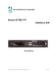
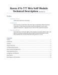
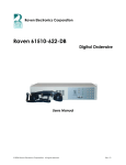
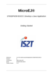
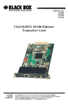
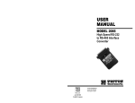
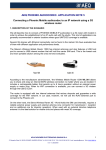
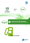
M4x Blade Quick Start Guide
Please Read Before You Start
Thank you for purchasing the M4x Blade.
When unpacking your M4x Blade confirm the following items
were received with your shipment.
♦
Software CD
This CD also includes the User Manual
♦
AC Power Supply Adapter
120/240 VAC, 12 VDC 2.5 Amp regulated
(Note: on units powered from a DC source, this item
will not be included)
♦
Power Cord
(Note: on units powered from a DC source, this item
will not be included)
♦
USB Cable
If any of these items are missing, please contact Sales at
775-858-2400, press 2.
Installing The M4x Software
Note: Install this software before plugging in the M4x Blade.
1.
Uninstall old M4x Software before installing a new version.
2.
Install the software by inserting the CD into the computer’s
CD Drive.
3.
We recommend selecting “Easy Install” when prompted.
4.
Follow the on-screen prompts to complete the installation.
5.
Refer to the M4x User Manual included on the software disk
for more detailed installation instructions, (especially if this
version of software will be installed over a prior version of
software).
LED Indicators
There are seventeen LED indicators on the front panel of the
M4x Blade as shown in Figure 2.
There are two LEDs per Port. The first LED is Red (default is
XMT (Output)). The second LED is Green (default is RCV
(Input)).
There is a Power On LED which is also Green to let the user
know the M4x Blade is powered on.
Figure 2
For more details regarding how the LEDs can be set to indicate
PTT (E-Lead) or COR (M-Lead), please refer to the M4x User
Manual.
M4x Port Pin Outs
On top of each M4x Blade, there are labels with pin out
information for each port installed in the M4x Blade. Please
note, the pin order is grouped for clarity.
12345678
Note: E-Lead is PTT, M-Lead is COR
MODULE 476-150 4-WIRE INTERFACE
MODULE 476-151 4-WIRE INTERFACE
PIN 1
PIN 1
RCV
PIN 2
PIN 3
M-LEAD
PIN 6
PIN 4
Powering Up the M4x Blade
1.
Connect the Power Cable into the AC Power Adapter.
2.
Connect the AC Power Adapter to your AC power source
(e.g. 3-pronged grounded wall outlet). The AC Power
Adapter can be connected to a 100 to 240 VAC, 50-60 Hz,
0.5A source.
3.
Connect the DC plug from the AC Power Adapter into the
DC jack on the rear of the M4x Blade as shown in Figure 1.
Figure 1
XMT
PIN 5
PIN 7
E-LEAD
PIN 8
PIN 1
PIN 2
PIN 3
PIN 6
PIN 4
PIN 5
PIN 7
PIN 8
RCV
M-LEAD
XMT
E-LEAD
PIN 2
PIN 3
PIN 6
PIN 4
PIN 5
PIN 7
PIN 8
RCV
M-LEAD
XMT
E-LEAD
PIN 1
PIN 2
PIN 3
PIN 6
PIN 4
PIN 5
PIN 7
PIN 8
RCV
M-LEAD
XMT
E-LEAD
WWW.RAVENCOMM.COM
MODULE 476-152 2-WIRE INTERFACE
MODULE 476-175
PIN 1
PIN 1 = NC
PIN 1 = NC
PIN 1 = RLY 1 NC
PIN 1 = RLY 3 NC
PIN 2 = NC
PIN 2 = NC
PIN 2 = RLY 1 COM
PIN 2 = RLY 3 COM
PIN 3 = NC
PIN 3 = NC
PIN 3 = RLY 1 NO
PIN 3 = RLY 3 NO
PIN 4
PIN 4 =
PIN 4 = RLY 2 NC
PIN 4 = RLY 4 NC
PIN 5 = RLY 2 COM
PIN 5 = RLY 4 COM
PIN 2
PIN 3
PIN 6
2WIRE
M-LEAD
PIN 1
PIN 2
PIN 3
PIN 6
2WIRE
M-LEAD
PSTN
SNI
PSTN
MODULE 476-178
RELAY
PIN 4 = NC
PIN 4 = NC
PIN 5
PIN 5 = NC
PIN 5 = NC
PIN 6 = NC
PIN 6 = NC
PIN 6 = RLY 2 NO
PIN 6 = RLY 4 NO
PIN 7
PIN 7
PIN 7 = NC
PIN 7 = NC
PIN 7 = NC
PIN 7 = NC
PIN 8 = NC
PIN 8 = NC
PIN 8 = NC
PIN 8 = NC
PIN 8
E-LEAD
PIN 8
E-LEAD
PIN 5 =
MODULE 476-178
RELAY OPT – 02
MODULE 476-180
PIN 1 = RLY 1 COM
PIN 1 = RLY 5 COM
PIN 1 = I/O 1
PIN 1 = I/O 9
I/O
PIN 1
MODULE 476-777
PIN 2 = RLY 1 NO
PIN 2 = RLY 5 NO
PIN 2 = I/O 2
PIN 2 = I/O 10
PIN 2
PIN 3 = RLY 2 COM
PIN 3 = RLY 6 COM
PIN 3 = I/O 3
PIN 3 = I/O 11
PIN 3
PIN 4 = RLY 2 NO
PIN 4 = RLY 6 NO
PIN 4 = I/O 4
PIN 4 = I/O 12
PIN 6
PIN 5 = RLY 3 COM
PIN 5 = RLY 7 COM
PIN 5 = I/O 5
PIN 5 = I/O 13
PIN 4
PIN 6 = RLY 3 NO
PIN 6 = RLY 7 NO
PIN 6 = I/O 6
PIN 6 = I/O 14
PIN 5
PIN 7 = RLY 4 COM
PIN 7 = NC
PIN 7 = I/0 7
PIN 7 = I/0 15
PIN 7
PIN 8 = RLY 4 NO
PIN 8 = NC
PIN 8 = I/O 8
PIN 8 = I/O 16
PIN 8
ETH XMT
ETH RCV
ETH SHLD
ETH SHLD
VOIP
PIN 1
PIN 2
PIN 3
PIN 6
PIN 4
PIN 5
PIN 7
PIN 8
4W RCV
M-LEAD
4W XMT/2W
E-LEAD
Starting the M4x Blade Software
Configuring a Bridge
1.
Verify the M4x Blade is powered on
1.
2.
Connect the USB Cable to the M4x Blade as well as to the
computer
Configure the M4x Analog 4-Wire Module(s) before
configuring a Bridge.
2.
Located on the Computer Desktop, select “M4x Setting”
shortcut
The M4x Blade allows multiple bridge configurations to be
created on one blade.
3.
Click “System Bridging” on the right side of the screen.
4.
Drag various ports from the system components panel and
drop them onto the Port Name boxes in the Bridge
Configuration pop up box.
3.
4.
Once the program is open, select “Actions” menu in the
upper left are of the screen
5.
Select “Connect”
6.
Select “Local/USB”
7.
On the right-hand side of the screen, a new box will appear
8.
Press the “+” next to Communication System
9.
Click on “Blade” and factory settings will appear
This screen will show the following:
♦
The M4x Blade Firmware Revision
♦
The Modules Installed / Firmware Revision
♦
Any enabled features
10. Click on the “+” next to Blade (and its Node Address)
The items that appear will allow you to access the port
settings
11. Click on the “+” next to System Voting to create a Vote
Group or Groups (an optional feature)
5.
2.
Click on the “+” just to the left of the Blade, if you haven’t
already from prior instructions. All ports populated will
show a generic name until the user changes it.
Click on the port that you want to analyze or configure. The
Port Status, along with the Transmit and Settings control
buttons appear.
3.
Press the Settings button in order to expand the settings
screen.
4.
Click through the tabs to see various settings.
5.
When all changes have been made, click “Actions” menu
and then “Save Settings to Firmware”. This will save the
settings to the M4x Blade. Please note: the “Save” button,
only saves the changes on the computer and will not save
the settings onto the M4x Blade.
6.
After any changes have been made, please power cycle the
M4x Blade by unplugging the unit and plugging it back in.
Rev: E 2011
♦
If DTMF Bridge Group is enabled, the members of
the bridge are now able to be cross-patched
dynamically as remote users dial using DTMFenabled devices.
Click the check box “Enabled” to enable the bridge.
Configuring SNR Voting (Advanced Feature)
1.
Configure the M4x Analog 4-Wire Daughter Board(s) before
configuring a Vote Group.
2.
Click “System Voting” on the right side of the screen.
3.
Follow the wizard that appears.
4.
Click the “Add” button to enable the Voting group.
Performing an M4x Loop Back Test for a
4-Wire Analog Module
Please refer to the M4x User Manual for more detailed settings.
1.
If Broadcast is NOT checked, the associated
bridge group will be full conference.
Please refer to the M4x User Manual for more detailed settings.
12. Click on the “+” next to System Bridging to create a Bridge
Group or Groups
Configuring the M4x Analog 4-Wire Module
♦
The M4x Loop Back Test enables users to perform basic tests
for PTT and COR, XMT and RCV tones, as well as DTMF.
1.
Click “Actions” on the Menu (upper left corner of screen)
2.
Select “Loop-back Test”
3.
Place the loopback cable firmly into a M4x Blade port to test.
4.
Select the port to test (be sure the cable is in the same port)
5.
Select the Loopback Tab
6.
Select to Test All or the Specific Test and click Test
7.
Testing status and Pass/Fail notifications will populate as
the M4x Blade goes through the specified tests.
Thank you for choosing a Raven Electronics M4x Blade for
your Communication needs, where we are the idea shop
committed to solving engineering problems and exceeding
expectations.