1
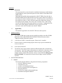
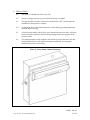
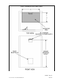
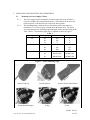
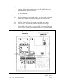
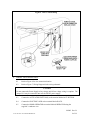
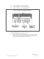
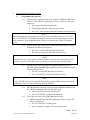
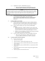
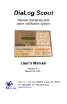
Installation and Operating Instructions ADA EZ Trash Room Door ADA EZ Trash Room Door Installation and Operating Instructions 910002 Rev. B To obtain the latest manual and template revisions or to view installation and programming videos go to www.ADAEZ.com. For technical support call (877) 232-3987 910002 Rev. B © 2013 ADA EZ. ALL RIGHTS RESERVED. 1 of 14 PURPOSE 1.1 Discussion This manual provides system description, installation instructions, troubleshooting recommendations, and a replacement parts list for the ADA EZ Trash Room Door (TRD) product. When properly installed and programmed, the ADA EZ TRD will put the door in the HOLD OPEN function when the DK12 presence sensor detects an occupant in the sensing area after an automatic open cycle. The DK12 presence sensor looks at the sensing area, makes a “map” of the area, and sends a signal to the operator if the sensing area has changed. The sensor will re-learn the “map” of the sensing area after an adjustable period of time (default is one minute). Adjustments to the sensor can be made using the OPTIONAL wireless remote p/n 1027-R. An electric lock is NOT included in the ADA EZ TRD kit. 1.2 Applicability This manual is applicable to the ADA EZ- TRD series door operator. 2. 3. PREREQUISITES 2.1 The ADA EZ TRD door operator must be installed according to the ADA EZ PRO INSTALLATION AND OPERATING INSTRUCTIONS (document number 700002) included with the door operator. 2.2 A Fail Secure, 24VDC 1A maximum power, Electric lock is installed. 2.3 Protective barrier (caution/warning tape) has been set up to prevent unauthorized access to work area. 2.4 Power has been shut off. 2.5 The 24VDC power supply cabinet contains an RF transmitter that is learned to the door operator. The Power supply and Operators are numbered to ensure they remain as a paired set. If the units get separated, it will be necessary to sync the Power Supply assembly with the Door Operator. Refer to section labeled “Linking the RF Interface Module” for instructions to link the Power Supply assembly and Door Operator. SYSTEM DESCRIPTION 3.1 General The ADA EZ Interface Module is shipped in the following components: ADA EZ TRD door operator Armored Door Cord (2) Door Cord Mounting Brackets 20 Feet of Operator Power and Signal wire Mounting Hardware 24VDC power supply with mounted Sensor Installation and Operation Manual 910002 Rev. B © 2013 ADA EZ. ALL RIGHTS RESERVED. 2 of 14 4. PRECAUTIONS 4.1 This product is intended for interior use only. 4.2 The power supply must not be powered until all wiring is complete. 4.3 The operator battery must be removed or switched to the “OFF” position until the installation of the operator is complete. 4.4 An operating door creates pinch hazards. Be careful making operating adjustments while the door is moving. 4.5 All wiring must comply with all local, state, and national electrical codes. All wiring must be secured to prevent it from becoming entrapped in the moving parts of the operator or door. 4.6 The installation must be fully complete and verified for proper function or the door must be disabled prior to the installer leaving the installation. An incomplete installation may cause serious injury. Figure 1. Power Supply Cabinet with Sensor 910002 Rev. B © 2013 ADA EZ. ALL RIGHTS RESERVED. 3 of 14 Figure 2. Mounting the Power Supply Cabinet 910002 Rev. B © 2013 ADA EZ. ALL RIGHTS RESERVED. 4 of 14 5. INSTALLING AND MOUNTING THE COMPONENTS 5.1 Mounting the Power Supply Cabinet 5.1.1 The power supply must be mounted in a location where the sensor will have a clear line of sight to the required detection area. This location can be above the trash receptacle, on an adjacent wall or above the door operator. 5.1.2 The mounting distance from the floor to the bottom of the sensor must be a minimum of 7 ft. Refer to Figure 2 which shows the Sensor area. The sensor area is dependent on the mounting height and angle of the sensor according to the Table 1 below. The mounting angle may be adjusted as shown in Figure 3. Table 1 Height Mounting Angle A B 7'3" 20 3'3" 5' 26 4'3" 5' 32 6' 6' 8'3" 20 3'6" 5'3" 26 5'6" 5'3" 32 6'9" 6'3" 9'6" 20 4'6" 6'6" 26 DO NOT USE DO NOT USE 32 DO NOT USE DO NOT USE Figure 3 – Sensor Mounting Angle Remove End Cap 20 deg (Standard Angle) Loosen Setscrew 26 deg Remove Sensor from Bracket 32 deg 910002 Rev. B © 2013 ADA EZ. ALL RIGHTS RESERVED. 5 of 14 5.1.3 The sensor may be relocated from the front of the power supply cabinet if necessary. Replace the two mounting screws into the mounting holes after removing the sensor from the front cover. 5.1.4 The sensor area can be adjusted. Refer to the included DK-12 user’s manual for sensor adjustment 5.2 Features and Functions 5.2.1 The Power Supply is pre-wired at the factory. The Electric Lock, Activation Buttons, and 3 conductor wire that provides power and signal to the door operator must be connected as part of the installation. 5.2.2 JUMPER – Jumper PS-1 can be removed to turn off the power supply. 5.2.3 LOCK DELAY – The lock delay is the time delay between receiving an activation signal and initiating an automatic open cycle and is selectable. The time delay can be set to 0, ½ second, 1 second, and 2 seconds. The lock delay is set to “0” from the factory and does not need to be adjusted for most installations. Figure 4. Power Supply Cabinet Components 910002 Rev. B © 2013 ADA EZ. ALL RIGHTS RESERVED. 6 of 14 All switches set to off = no time delay Switch 1 set to on = ½ second delay Switch 2 set to on = 1 second delay Switch 3 set to on = 2 second delay 6. 5.2.4 LOCK – Provides a 24VDC 1A maximum power output to activate an electric lock. 5.2.5 ACT Button – Provides and activate signal which will unlock the door and cause the operator to enter an automatic open cycle. 5.2.6 OPERATOR – Provides a 24VDC power output and signal to the ADA EZ Door Operator. 5.2.7 FIRE PANEL – When the FIRE PANEL contact is open the interface module will cause the operator to close the door and ignore all activation signals. If the FIRE PANEL option is not desired the jumper must be left in place. WIRING THE DK12 OCCUPANCY SENSOR 6.1 The DK-12 sensor comes mounted to the power supply box and is pre-wired at the factory. If it is necessary to relocate the sensor, it must be wired as follows: 6.1.1 Connect the RED wire to position 1 (PWR) on the DK12 Terminal Block. Connect the RED wire to the terminal block location labeled SENSOR “+”. 6.1.2 Connect the BLACK wire to position 2 (PWR) on the DK12 Terminal Block. Connect the BLACK wire to the terminal block location labeled SENSOR “-“. Connect the GREEN wire to position 3 (COM) on the DK12 Terminal Block Connect the GREEN wire to the terminal block location labeled SENSOR GRN. Connect the WHITE wire to position 4 (NO) on the DK12 Terminal Block. Connect the WHITE wire to the terminal block position labeled SENSOR WHT. 6.1.3 6.1.4 910002 Rev. B © 2013 ADA EZ. ALL RIGHTS RESERVED. 7 of 14 7. WIRING THE DOOR OPERATOR Figure 5. Route Wires Through Door Cord 7.1 Refer to Figure 5 and route the power and signal wires from 24VDC power supply to the door operator under the wire channel and wire exit hole on the door cord mounting bracket. 7.2 Using the mounting screws provided, secure the door cord mounting bracket behind the battery pack location. 7.3 Refer to Figure 5 and route the power and signal wires through the armored door cord to the interface module. 7.4 Apply the door cord mounting bracket cover over the mounting bracket to secure the door cord in place. 7.5 Secure the other door cord mounting bracket to the adjacent wall or frame using the mounting screw provided. 910002 Rev. B © 2013 ADA EZ. ALL RIGHTS RESERVED. 8 of 14 Figure 6. Door Cord Mounting 8. WIRING THE POWER SUPPLY 8.1 Refer to Figure 6 for wire connection location. 8.2 Refer to Figure 7, Wiring Diagram for the wiring schematic. CAUTION Do not connect the Power Supply to line voltage until all low voltage wiring is complete. The jumper PS-1 may be removed to turn off the 24VDC power supply. 8.3 Connect the ACTIVATION BUTTON(S) to the terminal labeled ACT BUTTON. 8.4 Connect the ELECTRIC LOCK to the terminal labeled LOCK. 8.5 Connect the DOOR OPERATOR to terminal labeled OPERATOR using the supplied 3 conductor wire. 910002 Rev. B © 2013 ADA EZ. ALL RIGHTS RESERVED. 9 of 14 8.5.1 Connect the RED wire to the terminal labeled “+” 8.5.2 Connect the GREEN wire to the terminal labeled “-“ 8.5.3 Connect the BLUE wire to the terminal labeled “SIG” Figure 7. Wiring the Power Supply Terminal Block 8.6 Connect the POWER SUPPLY to 115VAC line voltage. 8.6.1 Ensure jumper PS-1 is in place and verify: a. The LED located on the door operator POWER PACK illuminates STEADY GREEN. If the LED does not light, REVERSE polarity is being supplied to the door operator and the connection must be corrected. 910002 Rev. B © 2013 ADA EZ. ALL RIGHTS RESERVED. 10 of 14 Figure 8. NYC TRD Wiring Schematic 910002 Rev. B © 2013 ADA EZ. ALL RIGHTS RESERVED. 11 of 14 9. PROGRAMMING INSTRUCTIONS 9.1 Programming the Operator 9.1.1 Refer to Figure 5 and, at the base of the controller, PRESS and HOLD the “SELECT” and “ENTER” pushbuttons for three seconds. The following shall occur: The operator shall enter program mode. LEDs DS8 through DS11 shall flash green briefly. The “CLS” (close) position LED shall illuminate red and remain lit. NOTE When performing the auto-tune process for the first time, LED indications for “CLS,” “OP,” and “AUTO SETUP” will be RED, indicating that no values have been previously stored for those parameters. When programming the operator a second time the LEDs will illuminate green. 9.1.2 With the door in the closed position, PRESS and RELEASE the “ENTER” pushbutton. The following shall occur: The “CLS” position LED shall flash green briefly. The “OP” (open) position LED shall illuminate next. NOTE Wait until the “OP” (open) position LED illuminates to move the door to the open position. Failure to wait to move the door may cause the door to auto-tune in the wrong direction. 9.1.3 With the door in the fully open position, PRESS and RELEASE the “ENTER” pushbutton OR PRESS and RELEASE the pushbutton actuator. The following shall occur: The “OP” position LED shall flash green briefly. The “AUTO SETUP” LED shall illuminate red next. NOTE If the “ENTER” button is not accessible when the door is in the OPEN position, the Activate Pushbuttons may be used to set instead of pressing “ENTER” 9.1.4 RETURN the door to the fully closed position, and PRESS and RELEASE the “ENTER” pushbutton. The following shall occur: 9.1.5 The door shall open partially and then close. The “AUTO SETUP” led shall illuminate green. To exit the Auto Tune mode, PERFORM the following: PRESS and HOLD the “ENTER” pushbutton for three seconds. The following shall occur: a. The “AUTO SETUP” led shall go out. Auto Tune shall be complete. The door shall be tuned. 910002 Rev. B © 2013 ADA EZ. ALL RIGHTS RESERVED. 12 of 14 9.1.6 To RESET the controller, PERFORM the following: While pressing and holding the “ENTER” pushbutton on the controller, PRESS and RELEASE the “RESET” pushbutton. NOTE Resetting the controller does not reset the Interface Module linking to the operator controller. The interface module is linked to the door operator controller when shipped from the factory. If the interface module is replaced, the module will need to be linked to the Operator Controller. 9.1.7 9.2 If further door adjustments are necessary, refer to the Section titled “Customizing the Operator Settings” in the ADA EZ PRO INSTALLATION AND OPERATING INSTRUCTIONS (document number 700002) included with the door operator and PERFORM adjustments. Linking the RF Interface Module 9.2.1 The RF transmitter supplied with the power supply is linked to the door operator at the factory. If the RF memory is reset or the RF transmitter is replaced the Operator must be manually linked with the RF transmitter. 9.2.2 To link an Interface Module with a door controller, PERFORM the following: a. PRESS and HOLD the “LEARN” pushbutton on the controller until LEDs DS8 through DS11 flash green. The controller shall shall remain in the learn mode for 20 seconds or until the RF signal is received. b. 9.2.3 PUSH the Activation Pushbutton. LED DS7 shall flash green indicating that the operator accepted this RF pushbutton. To remove all RF pushbuttons from memory, PERFORM the following: 9.3 While pressing and holding the “LEARN” pushbutton on the controller, PRESS and RELEASE the “RESET” pushbutton. Verify the function of the Door Operator 9.3.1 Press the activations buttons The Electric Lock unlocks The Door Operator completes and automatic open cycle The Door Operator remains in HOLD OPEN while the LED on the DK12 sensor is lighted. The Door Operator remains in HOLD OPEN for 5 seconds after the LED light goes off Once the door begins to close the operator will ignore the signal from the presence sensor. The Door Operator closes and remains closed. 910002 Rev. B © 2013 ADA EZ. ALL RIGHTS RESERVED. 13 of 14 10. TROUBLESHOOTING INSTRUCTIONS 10.1 Refer to the Table Below for a listing of fault symptoms and recommended remedies. Table 2. Troubleshooting Recommendations Symptom The Operator does not Learn Open Position when pressing the Activate Pushbutton. Recommended Remedy The RF transmitter in the Power Supply assembly is not learned to the Door Operator. Refer to section labeled “Linking the RF Interface Module” for instructions to link the Power Supply assembly and Door Operator Verify that the contact is closing when the activation buttons are pressed Verify that the power supply for the electric lock is powered Verify that the electric lock is a Fail Secure lock Verify that the Interface Module RF is learned to the Door Operator Controls. 1. On the Opertor Control board, PRESS and HOLD “LEARN”, PRESS and RELEASE “RESET” OR The Operator does not Open when pressing the Activate Pushbutton The Electric Lock does not unlock The Electric Lock unlocks but the Operator does not open The Operator begins to close, but re-opens during a close cycle PRESS and RELEASE “LEARN” unitil LEDs DS8-DS11 slowly Flash GREEN 3. Press and release the ACTIVATION PUSHBUTTONS LED DS7 quickly flashes GREEN and goes out Verify that the Door Operator is programmed for Occupancy sensor input 1. On the Operator Control board, PRESS and HOLD “SELECT”, for 10 seconds OR The Operator begins to open when the DK12 sensor LED lights 2. 2. Rotate the Potentiometer until DS10 lights GREEN 3. PRESS and RELEASE the “ ENTER” button on the control board to store the setting. PRESS and HOLD the “ENTER” button for 3 seconds to exit programming mode. The Operator begins to open before the Electric Lock is unlocked Refer to the section titled LOCK DELAY and increase the lock delay time Problems with the DK12 sensor Refer to the DK12 USER GUIDE troubleshooting section 910002 Rev. B © 2013 ADA EZ. ALL RIGHTS RESERVED. 14 of 14