1
Project no. 222422
Project acronym: ECCell
Project title: Electronic Chemical Cell
Instrument:
STREP/FET OPEN
Thematic Priority: Theme 3 Information and Communication Technologies
Deliverable n. 5.3: prototype, restricted to other partners (PP)
Completed software system for programming and optimizing ECCells.
Part 2 – User Manual
Due date of deliverable: 31. 12. 2011
Actual submission date: 05. 03. 2012
Start date of project: 1.09.2008
Organisation name of lead contractor for this deliverable:
University of Southern Denmark (SDU), Steen Rasmussen
Ruhr-Universität Bochum (RUB-BioMIP), John McCaskill
Duration: 40 months
User's-Manual of BioPRO-Software
Uwe Tangen
March 5, 2012
Ruhr-University Bochum BioMIP, NC1/73, 44780 Bochum, Germany
Version 0.5
1
Contents
1 Introduction
1.1
5
Installation instructions
. . . . . . . . . . . . . . . . . . . . .
1.1.1
Operating system requirements
. . . . . . . . . . . . .
1.1.2
Directory trees and installation
5
6
. . . . . . . . . . . . .
6
1.2
Running the software . . . . . . . . . . . . . . . . . . . . . . .
7
1.3
Feedback-loops and level-one elements
8
. . . . . . . . . . . . .
2 User-Interface
2.1
9
Perl-TK user-interface ('startbio') . . . . . . . . . . . . . . . .
2.1.1
Session-tab
. . . . . . . . . . . . . . . . . . . . . . . .
10
2.1.2
Path-tab . . . . . . . . . . . . . . . . . . . . . . . . . .
11
2.1.3
Design-tab . . . . . . . . . . . . . . . . . . . . . . . . .
12
2.1.4
FPGAs and bit-les . . . . . . . . . . . . . . . . . . . .
13
2.1.5
Post processing
13
. . . . . . . . . . . . . . . . . . . . . .
2.2
Console terminal
2.3
Windows as user-interface
. . . . . . . . . . . . . . . . . . . . . . . . .
. . . . . . . . . . . . . . . . . . . .
14
14
2.3.1
Colors and fonts etc.
. . . . . . . . . . . . . . . . . . .
14
2.3.2
Zooming . . . . . . . . . . . . . . . . . . . . . . . . . .
17
2.3.3
Mouse buttons and cursor-keys
. . . . . . . . . . . . .
17
. . . . . . . . . . . . . . .
17
2.3.3.1
Left-mouse button
2.3.3.2
The center mouse-button:
2.3.3.3
The right mouse-button typically means inversion of operation.
2.4
9
. . . . . . . . . . .
. . . . . . . . . . . . . .
2.3.4
Data base, export and import of objects
2.3.5
Sensors and actors
19
19
. . . . . . . .
19
. . . . . . . . . . . . . . . . . . . .
20
Camera window . . . . . . . . . . . . . . . . . . . . . . . . . .
21
2.4.1
Camera-knobs and status-information . . . . . . . . . .
22
2.4.2
Storing video-sequences . . . . . . . . . . . . . . . . . .
23
2.4.2.1
. . . . .
24
Information appended to each image
2.4.3
Storing snap-shots
. . . . . . . . . . . . . . . . . . . .
25
2.4.4
Long-term measurements . . . . . . . . . . . . . . . . .
25
2
CONTENTS
2.4.5
2.5
CONTENTS
2.4.4.1
General principle . . . . . . . . . . . . . . . .
26
2.4.4.2
How to create a new measurement chain . . .
27
2.4.4.3
Changing the measurement chain . . . . . . .
27
2.4.4.4
Moving the measurement chain
. . . . . . . .
28
2.4.4.5
Modifying measurement parameters . . . . . .
28
Synchronizing camera's output with the uidic-design .
28
Design window
. . . . . . . . . . . . . . . . . . . . . . . . . .
. . . . . . . . . . . . . .
30
2.5.1
Pumps-control and denition
2.5.2
Shift-register and basic electrode control
. . . . . . . .
32
2.5.3
Level-one elements control . . . . . . . . . . . . . . . .
34
2.5.4
Sequences control . . . . . . . . . . . . . . . . . . . . .
37
3 Interfaces
30
39
3.1
Hardware Interfaces . . . . . . . . . . . . . . . . . . . . . . . .
39
3.2
DPD-Interface (dissipative particle dynamics)
40
3.3
Client-Server Interface
. . . . . . . . . . . . . . . . . . . . . .
41
3.4
Bio@Fox-Interface . . . . . . . . . . . . . . . . . . . . . . . . .
42
3.5
Simulation interface . . . . . . . . . . . . . . . . . . . . . . . .
43
3.6
The scripting-interface
. . . . . . . . .
. . . . . . . . . . . . . . . . . . . . . .
45
3.6.1
Initialization of system and attached hardware . . . . .
45
3.6.2
Graphics . . . . . . . . . . . . . . . . . . . . . . . . . .
46
3.6.2.1
Commands to specify state-machines. . . . . .
46
3.6.2.2
Controlling the graphical interface
. . . . . .
47
3.6.3
Feedback-control
. . . . . . . . . . . . . . . . . . . . .
48
3.6.4
Controlling attached hardware . . . . . . . . . . . . . .
49
3.6.5
Programming
49
. . . . . . . . . . . . . . . . . . . . . . .
3.6.5.1
Initialization
3.6.5.2
Commands
. . . . . . . . . . . . . . . . . .
51
. . . . . . . . . . . . . . . . . . .
51
3.6.5.3
Testing conditions
. . . . . . . . . . . . . . .
55
3.6.5.4
Status-codes
. . . . . . . . . . . . . . . . . .
55
3.6.5.5
Return-codes
. . . . . . . . . . . . . . . . . .
55
3.6.5.6
Special values . . . . . . . . . . . . . . . . . .
56
3.7
Runtime-parameters
. . . . . . . . . . . . . . . . . . . . . . .
56
3.8
Design environment details . . . . . . . . . . . . . . . . . . . .
57
4 Level-One
4.1
58
Basic elements . . . . . . . . . . . . . . . . . . . . . . . . . . .
59
4.1.1
BARRIER . . . . . . . . . . . . . . . . . . . . . . . . .
59
4.1.2
CATCHER
60
4.1.3
General
. . . . . . . . . . . . . . . . . . . . . . . . . .
60
4.1.4
Neuron . . . . . . . . . . . . . . . . . . . . . . . . . . .
61
. . . . . . . . . . . . . . . . . . . . . . . .
3
CONTENTS
4.2
CONTENTS
4.1.5
TRAP . . . . . . . . . . . . . . . . . . . . . . . . . . .
61
4.1.6
TRIGGER . . . . . . . . . . . . . . . . . . . . . . . . .
62
4.1.7
SPREADER . . . . . . . . . . . . . . . . . . . . . . . .
63
Networks . . . . . . . . . . . . . . . . . . . . . . . . . . . . . .
64
5 Programmers-Manual
5.1
65
Drivers interface . . . . . . . . . . . . . . . . . . . . . . . . . .
65
5.1.1
Parallel-port . . . . . . . . . . . . . . . . . . . . . . . .
65
5.1.2
Camera-driver . . . . . . . . . . . . . . . . . . . . . . .
66
5.1.2.1
Camera data-structure . . . . . . . . . . . . .
67
Andor-CCD . . . . . . . . . . . . . . . . . . . . . . . .
67
5.1.3
6 Miscellaneous
6.1
68
GTK+-2-installation instructions for MacOS-X and other UNIXderivatives.
. . . . . . . . . . . . . . . . . . . . . . . . . . . .
68
6.2
Revision history . . . . . . . . . . . . . . . . . . . . . . . . . .
69
6.3
Release Notes . . . . . . . . . . . . . . . . . . . . . . . . . . .
69
Bibliography
71
4
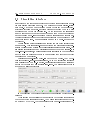
Chapter 1
Introduction
This manual is meant for normal users as well as software-developers using
the electronically controlled microuidic chips - BioModules .
The overall goal for this software is to facilitate and operate these microuidic chips with hundred or more electrodes and many dierent variants
of uidic designs.
This task is dicult and the average reader should not
expect to utilize the full power of the software and these special chips after a
few minutes of training. To illustrate the complexity of the software: about
two hundred thousands lines of code and several man-years of development
are behind what is described in this manual.
The software, so far, is running on Linux, MacOS-X and potentially every
other Unix-like operating system. Binaries can be provided on short notice
(given that the according computer plus compiler is available).
Essentially three parts are provided with this software, a Perl-script which
operates the ng_biopro-software, several design-les for uidics, electronics
and FPGAs (eld programmable gate arrays) .
1.1
Installation instructions
An experienced Unix-manager should install this software. Two environment
variables are required to be set in advance: HOME which points to the homedirectory of the user running this software and NGEN_DESIGN pointing to
the design-tree with all binaries and design-les, see section 1.1.2. Furthermore it is expected that the user has a directory in his executable search
path which is owned by himself, which typically is $HOME/bin.
5
1.1. INSTALLATION INSTRUCTIONS CHAPTER 1. INTRODUCTION
1.1.1 Operating system requirements
The operating system requirements for Linux (Version 9.0 and higher) are
available in most of the distributions.
The software uses X11, GTK-+2
(pango, atk, freetype, fontcong ...), readline and Perl-TK. With MacOS
things are more complicated, because the programming environment by default usually only supports X11. Perl-TK and GTK-+2 have to be compiled
and installed separately.
This can become quite tedious and cumbersome
and is usually only be manageable by an experienced system-manager, the
Xcode utilities and the X11-development-environment from Apple have to
be installed prior, see 6.1.
1.1.2 Directory trees and installation
A default installation would look like this:
$HOME an environment-variable containing the path of the user's-data
area, $HOME/bin, a directory which is in the search path for executables
(the name 'bin' is not mandatory, every other name would suce also),
$HOME/sessions, a directory which will be created during installation and
which serves as a root for sessions using this software (the name 'sessions' is
hard coded in the starting script 'startbio') and last but not least the designenvironment, $HOME/bioenv, which contains all binaries and design-les
usable by the software (the name 'bioenv' is not mandatory but has to be
dened in the environment variable NGEN_DESIGN). Updates of the software will change or add les below this directory.
Further directories which are provided during the installation-procedure
are $HOME/sessions/session_template (a directory which contains native
design-les used to start the software), $NGEN_DESIGN/bin, the directory
tree containing all available binaries of that revision (e.g. ng_biopro_i686),
$NGEN_DESIGN/design, a directory tree containing all design-les available (you can add further design les at all times if you obey certain naming
conventions, see section 3.8) and $NGEN_DESIGN/icons, the full collections
of icons used by the software.
Three container-les are provided: bioenv_shipped.tar.gz, sessions_shipped.tar.gz,
bioenv_uidic.tar.gz. All three of them should be unpacked in the HOMEdirectory.
A typical installation comprises the following steps:
1. unpack the tar-archive in the home-directory or where ever the user
has write access to.
6
1.2. RUNNING THE SOFTWARE
CHAPTER 1. INTRODUCTION
2. let the environment variable NGEN_DESIGN point to the newly created sub-directory 'bioenv'.
Verify that HOME points to the users
home-directory. With bourne-shells the command looks like: 'export
NGEN_DESIGN=/home/myuser/bioenv/'.
3. create a link 'startbio' in a directory which is in the user's search path
for executables (e.g. ln -s $NGEN_DESIGN/bin/startbio $HOME/bin/startbio).
Please be aware that site-specic changes are made in 'startbio' and
have to be updated with a new 'startbio'-le installed.
4. Run the script 'startbio' and provide the missing libraries which are
mentioned as error-messages at several levels of the startup-procedure
(this step probably has to be accompanied by someone who has rootaccess (super-user) and knows the concept of libraries).
1.2
Running the software
The usual mode of operation is executing the script 'startbio'. This should
be done once per experiments-day.
It is not important at which specic
place this script is executed. All le-creations and changes are done below
$HOME/sessions. Calling 'startbio' ensures that the user is able to choose
from the designs available, change further runtime-parameters and gets a full
log of all operations during the session. If 'startbio' is called the rst time it
creates a new session_{date}-folder and all logs and data-les are stored in
that directory.
At start-up of 'startbio' a Perl-TK window opens and lets the user choose
parameters. Essentially the user is asked about the hardware-setup, whether
and how many pumps are attached to the computer, what the interface
between computer and the BioModule is, whether a new sessions-directory is
to be created (if it is already available) and whether the BioModule should
be congured or not.
See section 2.1 for a detailed description of all the
features of this interface.
With the button 'Start' the real ng_biopro-software is launched. With
the button 'Exit' the Perl-TK script 'startbio' nishes and gives control back
to the user. When ng_biopro is launched the 'startbio'-scripts goes suspend,
it is no longer reacting to user-events.
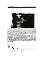
With launching ng_biopro a big Xterm-window is opened executing the
ng_biopro-software with the attached runtime-parameters.
Through this
Xterm-window the ng_biopro-software can be controlled on a console-level,
a simple prompt using the readline-library, is provided, see section 3.6 for
an explanation of all possible commands and features.
7
During the boot
1.3. FEEDBACK-LOOPS AND LEVEL-ONE
CHAPTER
ELEMENTS
1. INTRODUCTION
process of the ng_biopro-software specied design-les are read-in, contact
is established to the dened hardware-resources and an X-windows based
graphical user-interface is opened, see chapter 2 for further details.
A multitude of error-checks are undertaken and it might very well be that
a lot of error-messages occur if something with the hardware or the designs
fail.
When the uidic- and the electronic design is visible in one window
and the current camera image in another window as well the software is
operational.
1.3
Feedback-loops and level-one elements
The major objective of the integrated system environment 'ng_biopro' is
to provide the ability of using electronics to directly control biochemistry
situated in micro-uidic channels.
This objective requires full access to the images produced by the camera
and as much control as possible on all actuators available in the system.
With the Bio@Fox-box many of these actuators can be accessed.
The direct electronic control of biochemistry allows immediately the creation of a multitude of feedback-loops in the system. The uorescence images
from the camera are evaluated at certain regions of interest (ROI), intensityvalues are calculated and due to several already dened or yet to be dened
regulatory elements (all written in software) commands for the actuators
(electrodes, xy-table, aotf, lters etc.) are derived.
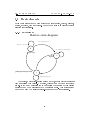
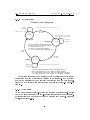
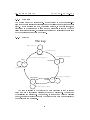
Currently, seven dierent simple-feedback-loop elements are dened: CATCHER,
BARRIER, NEURON, TRAP, TRIGGER, SPREADER and GENERAL.
You can nd specic descriptions of these 'level-one-elements' in chapter 4.
8
Chapter 2
User-Interface
The user-interface comprises several levels of interaction with the system. As
a preparation on what the software should do a Perl-TK script ('startbio')
species the hardware to be used during the session.
A low-level interface (console based) gives the user access to special features and an intermediate programming language and provides debugging
facilities in case of failures. This low-level interface also provides communication with the program 'ng_biopro' in case of a missing graphical environment, see 3.6.
The third user-interface level is the graphical user-interface with clickable buttons and design-data presented graphically. Further interfaces exist
which allow the program to communicate with other programs, or to setup
a client-server-operation scheme.
All these interfaces are described in the
sequel.
2.1
Perl-TK user-interface ('startbio')
The Perl-TK user-interface serves two purposes. The rst is to provide an
easy to use navigation tool allowing the user to choose between dierent
design variants and to tell the software which hardware conguration to
use.
In addition, path-information is dened including a simple session-
management and logging. The second purpose is to provide a user-editable
script which allows customization to the users' need of course only with a
person able to handle Perl-scripts.
The ng_biopro-software uses several dierent input-interfaces.
Two of
them are utilized by this 'startbio'-script, the scripting interface and runtime
parameters. For runtime parameters of the program, see section 3.7.
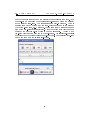
When starting the 'startbio'-script the 'Session-tab' is displayed.
9
2.1. PERL-TK USER-INTERFACE ('STARTBIO')
CHAPTER 2. USER-INTERFACE
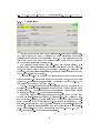
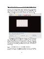
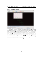
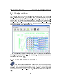
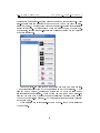
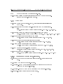
2.1.1 Session-tab
This is the rst window seen after the 'startbio'-script has been launched.
The user is allowed to dene a directory in which all logging and further
denitions of the software behavior will be saved. The two paths in the upper
half of the window are preset with default values which might be changed
via the buttons 'Select' on the right side.
The directory chosen in the rst path-entry has to exist already, it is
thought as the general container of all experiments conducted with this software. The second will be created, if not already existent. By switching o
the check-box 'Use existing session' a new directory will be created each time
the ng_biopro-software is started.
A further check-box 'Download XCS ' is provided to let the user decide
whether a plugged-in BioModule should be congured or not, if a BioModule
is attached. In all other cases, especially when using the Bio@Fox-box, the
chip will be congured by the Bio@Fox-box.
The ng_biopro-software supports an arbitrary number of pumps to be
addressed. This 'startbio'-scripts lets the user choose between zero and four
dierent pumps. The control window of these selected pumps is only visible
on request, see section 2.5.1 for a further explanation.
Due to a multitude of dierent hardware types, and many of them only
with simple serial-interfaces equipped, a real plug-and-play philosophy cannot be provided. Instead, the user is required to choose the hardware components by clicking at the appropriate check-boxes given as Device: and Camera: area. In the case shown above, 'par' means use of the parallel-port of the
computer. This is for users connecting the BioModule directly to the parallelport. The parallel-port must be congured in IEEE1284_MODE_COMPAT
mode, see section 5.1.1 for further specications.
10
2.1. PERL-TK USER-INTERFACE ('STARTBIO')
CHAPTER 2. USER-INTERFACE
If the software is operated with a MereGen-board, which is controlling
large parts of the setup, then the user is required to check the 'meregen' button. With no BioModule attached at all 'nodev' should be checked. Checking
the button 'cli' (client) and providing the appropriate name of the Bio@Foxcontroller (in principle IP-addresses might be sucient as well, but some
peculiar socket-issues will result sometimes in error-messages if not given a
real name) opens the connection to the according Bio@Fox-controller.
In principle, the ng_biopro-software supports several dierent types of
cameras.
Check the button 'no' if no camera is currently available.
If an
Andor-camera is provided check the button 'andor' and have a look into
section 5.1.3 for further information on the software-development-kit used in
this implementation. Even though rewire (IEEE 1394) is a generous camerabus each rewire-camera requires special control-ags to be set. The current
ng_biopro-software supports the Vosskuehler camera. With a Vosskuehler
camera attached, check the button 'vosskuehler'. With 'protolife' the driver
for a Cascade-II camera from Princeton Instruments is selected.
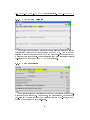
2.1.2 Path-tab
If the user doesn't have a special environment congured the paths given
in this section probably would not need any modication. In case you want to
test dierent designs, which are not given in the standard installation, these
paths let you dene what electrode-designs to be used, where the bitstreams
for the FPGAs to be found and what the required other uidic-variants are.
The user is allowed to specify dierent design-directory-paths using the
'Select'-button on the right side. If something changed in these directories
during runtime of the 'startbio'-script the user might press the 'ReScan'-
11
2.1. PERL-TK USER-INTERFACE ('STARTBIO')
CHAPTER 2. USER-INTERFACE
button. The 'startbio'-script then regenerates the scripts used when launching the ng_biopro-software the next time, see section 3.6.
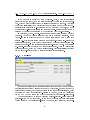
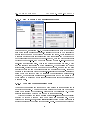
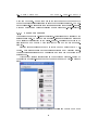
2.1.3 Design-tab
Depending on the BioModule attached and the concrete uidic-variant
realized, the user has to specify the design, e.g.
'Biopro3'.
After dening
the correct type, the Perl-TK-interface provides the available uidic-designs,
in this example 'Bubble', 'Fan', 'SegmFlow' or 'Standard'. With the uidic
design chosen, e.g.
'Fan', a further section becomes available: the uidic-
module - which shows check-boxes of the possible detailed variants of the
'Fan'-reactor design. In total several dozens dierent uidic-designs are available. The preview-button is especially useful because it allows the user to
look at the designs quickly.
These specications have to be done, because otherwise the user will be
not able to see which electrodes in the uidic-channels are eective and which
have contact to uids.
12
2.1. PERL-TK USER-INTERFACE ('STARTBIO')
CHAPTER 2. USER-INTERFACE
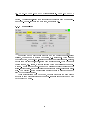
2.1.4 FPGAs and bit-les
Depending on the attached hardware this tab allows the user to specify
the bitstreams used for the conguration of the FPGAs.
The two upper
sections in this tab are only needed when the MereGen-board is used as the
major hardware control unit. The lower section shows the currently available
bit-les used to congure the FPGA of the BioModule.
2.1.5 Post processing
Some simple standard processing steps can be undertaken after experiments have been conducted. For example, the videos stored, are written as
pgm-les and probably needed to be converted into an mpeg-movie, or they
should be compressed to save disk-space.
13
2.2. CONSOLE TERMINAL
2.2
CHAPTER 2. USER-INTERFACE
Console terminal
A basic user-interface is given with a console window. This console is created
as an Xterm-window after pressing the 'Start'-button in the Perl-TK-script
or the ng_biopro-software is started itself from a console without any PerlTK-script. The sole function of the Perl-TK-script is to provide the wishedfor environment. This environment is dened via two interfaces, rstly the
program's runtime-parameters and secondly, via script-les which have been
created by the Perl-TK-script.
Runtime-parameters and these script-les
are user-visible. They provide all the necessary data for operation in case of
debugging or a non-graphical user-interface.
Especially when using the ng_biopro-software in server-mode the main
user-interface is provided with the ng_biopro-software working in clientmode somewhere else in the world. This client-server-communication is realized via a socket-based TCP/IP communication channel, see section 3.3.
2.3
Windows as user-interface
The major communication interface with the ng_biopro-software is realized
via two dierent graphical windows. One of these provide an on line-camera
screen and the other the electronic- and uidic design to allow the user to
navigate to areas of interest and to provide her with full low-level control of
the electrodes.
Each of these windows has dierent functionalities comprised in a menuarea at the top of each window.
Certain icons (with corresponding short
texts) usually raise new windows with specialized functions. Each of these
top-level-windows in addition contain two buttons each, for specifying colors
and text-fonts.
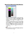
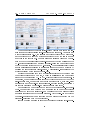
2.3.1 Colors and fonts etc.
Dening colors and fonts is done via two popup-windows shown below. The
icon shown represents the according functionality in the menu-bar of these
top-level-windows.
Dene and change colors
14
2.3. WINDOWS AS USER-INTERFACE
CHAPTER 2. USER-INTERFACE
There are two dierent types of colors to be specied. Discrete colors
which are used for selected items, switched on- or o-states of electrodes, sensor elements and uidic-channel representations. 16 dierent colors can be specied in this way.
What color is used for what
functionality is currently hard-coded in the user-interface and is not
customizable.
The second type of colors is a palette which might be a denable gradient, a random collection of colors or a rainbow. This palette is eective
for the camera-window where many dierent colors are needed. A suitably dened color-space allows the experimenter to enhance certain
aspects of the camera-screen. The colors dened here only aect what
the user sees on the display and do not inuence what is stored on disk
as a sequence of images, see section 2.4.2 for further information on
video-sequences.
Load fonts and map them for textual output. You only need to
provide a suitable name for the font. With xfontsel you will nd out
which fonts are currently available.
15
2.3. WINDOWS AS USER-INTERFACE
CHAPTER 2. USER-INTERFACE
Flip drawing-area horizontally
Only the view is ipped. The internal calculations are not aected.
Flip drawing-area vertically
Only the view is ipped. The internal calculations are not aected.
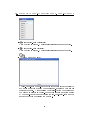
Add a log-book entry
The log-book-entry popup-window gives the experimenter the ability to
add notes at any time during the experiment. It is just a very simple
editable text eld.
After pressing the 'Close'-button the contents of
the window is printed in the log-book of this experiment accompanied
by two time-stamps (one for opening the log-book-entry-form and the
second for the time of closing the window).
16
2.3. WINDOWS AS USER-INTERFACE
CHAPTER 2. USER-INTERFACE
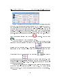
2.3.2 Zooming
Zooming is only possible in the design-window.
There is no restriction on
the depth of zooming. The procedure to zoom into a region of the design is
two draw a rectangular area with the left mouse-button (see section 2.3.3 for
notations) and then after releasing the left mouse-button clicking the middle
button. Zooming out is done with the right button, just clicking it at the
design window. Then the zoom jumps back to the former rectangular area.
The sketch of this area is shown in addition.
Zooming into this now old
region is done as before, just clicking the middle mouse-button.
There is no limit (apart from memory considerations) in how
many zoom-levels can be created.
The once created rectangular area can be modied.
Pressing the left-
mouse-button inside the area means moving it, pressing the left-mousebutton in direct vicinity of the edges, see 2.3.3 for further details, means
changing size.
Creating rectangles with the left-mouse-button in other top-level-windows
is also possible but zooming into these areas is not implemented, see 2.3.3.
2.3.3 Mouse buttons and cursor-keys
In general, the ng_biopro-software expects a three-button mouse at least.
This might be a problem for Windows oriented two-button-mouse-users as
well as for MAC-OS oriented single-button mouse users. In the sequel the
discussion about left and right is based on the assumption that the mouse
is used by a right-handed user.
For left-handed users and thus exchanged
button-meanings left and right are reversed.
2.3.3.1 Left-mouse button
Usually the left mouse button serves for selecting objects, drawing sensorareas and zoom-areas.
There are essentially four dierent types of action
when using the left-mouse-button:
Press-hold-and-move
With this operation the user creates a rectangular area. Currently, the
minimum-size of such a rectangular area is 10 pixels. After releasing
the left-mouse-button the rectangular area remains visible. The further
meaning of the area is then determined by the next mouse-click.
Clicking the left mouse-button
Several dierent possible reactions occur, depending on the context.
17
2.3. WINDOWS AS USER-INTERFACE
CHAPTER 2. USER-INTERFACE
Usually, clicking the left-mouse-button means selecting what is below
the pointer.
If there are several types of selectable objects a popup-
menu lets the user choose which of these types are to be selected. Selected objects are highlighted. The highlighting color can be changed,
see paragraph 2.3.1 on how to do this.
Already selected objects are deselected.
If this should not hap-
pen, then press the CTRL-button at the same time when the clicking
is done.
If already a rectangular area has been drawn, the eective selectingarea of the mouse-button is increased to the area's size, meaning that
all objects inside this rectangle are selected. Again a popup-menu appears, if dierent types of objects are to be selected. After selection,
the rectangular area disappears.
There is a special feature for electrodes (or pins) which lets the user
dene the polarity of these electrodes. When selecting an electrode the
default polarity is positive (usually 3.3V with Spartan-XL FPGAs ).
Pressing and halting the SHIFT-button before clicking on the electrode
reverses the polarity, in our example resulting in 0V potential at the
electrode. Just clicking on the electrodes does not actually mean activation of the electrodes. They stay in the state possessed before, see
section 2.3.5 for further details.
Every simple object has one selection point. This selection point is at
the center of the electrodes and at the upper left edge of the sensors,
see section 2.3.5 for details.
If sensors or electrodes are overlapping
unfavorably then zooming into the region usually helps to distinguish
these objects.
Pressing the left mouse-button:
Some objects, mostly sensors, are allowed to be moved around.
The
usual procedure to accomplish this, is to select the object, you see
the highlighted color, and then, while pressing the SHIFT-button in
addition, dragging the object over the screen. Typically you will see a
rectangular area emerging, which is removed after the object has been
moved.
When a rectangle is existing, the behavior depends on the position of
the mouse pointer. If the mouse-pointer is well inside the rectangular
area then the user is able to move this rectangular area by dragging
the pointer while pressing the left mouse-button.
If the mouse-pointer is fairly precise at an edge or a vertex of the
rectangular area then the size of that rectangular area can be changed
by dragging the pointer while pressing the left mouse-button.
18
2.3. WINDOWS AS USER-INTERFACE
CHAPTER 2. USER-INTERFACE
Double clicking the left mouse-button:
Currently, no functionality behind this event.
2.3.3.2 The center mouse-button:
Zooming-in into an already given rectangular area, when clicking. It
is not necessary to have the pointer inside this rectangular area, just
clicking is sucient. All other possible events, pressing, double-clicking
and in conjunction with other keys are not utilized.
Pressing the shift-button while clicking the center-mouse-button and
being located over a selectable object results in a bunch of further
information given in the session-log.
This information is meant for
debugging strange behavior and is usually not needed.
2.3.3.3 The right mouse-button typically means inversion of operation.
When clicking the right mouse-button inside a zoom-state then a zoomout-operation occurs. After zoom-out the rectangular area of the former zoom-in-rectangle is visible. If a rectangular area is visible then
this area is removed.
If no-zoom-out is possible and no rectangular area visible then all already selected objects are deselected.
Double click of the right mouse-button always means deselection of all
selected objects.
2.3.4 Data base, export and import of objects
The ng_biopro-software is equipped with an integrated database. The main
purpose for this database is to store all the complex conguration options
and user-dened control-structures to allow for a seaming-less continuation
in case of halting the program. This database is either stored in a binary container, e.g. 'ng_biopro_i686_Vbase.db_0' or a human-readable ASCII-le
'close.Vbase'. The database itself is a distributed object-oriented databasesystem. Especially for client-server operations the communication between
client and server is mediated via this database.
For reasons as backup and debugging it is possible to export the internal
database into a human-readable ASCII-form. The syntax is LISP-like with
all objects and their corresponding data is written in clear-text as is shown
19
2.3. WINDOWS AS USER-INTERFACE
CHAPTER 2. USER-INTERFACE
in the le close.Vbase. Of course, importing such an ASCII-database is also
possible. Import and export is available below the FILE-drop-down-menu in
the upper menu-bar.
Remark: the binary form of the database is neutral to little- and big-endian
machines.
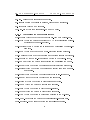
2.3.5 Sensors and actors
Besides the pure hardware control like pumps, camera and shutters the electronic control of electrodes is at the heart of the ng_biopro-software. Sensors
in the sense of this section have to be distinguished from e.g. temperaturesensors which are also controlled by this software but do have a clear physical
representation. The sensors in this section and if not otherwise noted in the
whole document are simple rectangular areas in the graphical windows.
In the camera-window these rectangular areas are regions of intensity
integration. All intensity values of pixels in this region are summed up and
divided by the number of pixels.
Arbitrary many sensors (in the current
version is an upper limit of 512 active sensors) can be dened and used to
derive decisions on whether to switch-on electrodes or not. The sensors in the
design-window are exactly the same with only two exceptions, rstly, they are
generated in advance and placed along interesting areas of the uidic-channels
(this eases the selection considerably). And secondly, the intensity values are
only available after camera- and design-window had been synchronized. How
this is done is explained in section 2.4.5.
20
2.4. CAMERA WINDOW
CHAPTER 2. USER-INTERFACE
Actors on the other side are simple electrodes which are electrically accessible for uids in the channels.
Not all electrodes are always accessible
because certain uidic-designs do not allow arbitrary dense channel-networks.
Though in the image above not only sensors (green rectangular areas) and
actors (brown rectangular areas) are shown but also blue traces which actually are wires connecting the electrodes with the controlling FPGA. The
galvanic accessibility is only given for the electrodes. All other parts of the
design are covered with an insulating
SiN2 -
or
SiO2
layer.
Of course the
isolation-layer is quite thin but for the frequencies and areas used no visible
inuence during the experiments could be observed.
2.4
Camera window
The camera-window is the rst top-level window. Essentially, it is a combination of four parts: a menu-bar with two drop-down-menus, File and Options
and a Help-button, an icon-menu-bar with often used functions, a drawingarea with the cameras output and some status-information and renement
knobs from the camera-control.
Generally, the camera-features used here are optimized in advance for the
tasks given and the user is only confronted with the most important options.
The camera-output shown in this window is only meant for cursory obser-
21
2.4. CAMERA WINDOW
CHAPTER 2. USER-INTERFACE
vation and not for high-denition precise microscopic views. High-precision
observations with the camera are reserved for programs specialized on that
task.
Here the focus is on the attachability of a broad range of cameras
without the users-need to study all the subtleties of the given hardware.
The scroll-bars at the drawing-area are dimensioned such that in principle
the whole camera-output can be viewed by scrolling through the dierent
areas.
Please note that the actual images picked up from the camera and
stored in videos are only from the visible part on the screen.
Non-visible-
parts do not enter the circular image-buer and are thus not stored in the
movies taken. When scrolling, certain delays might occur when changing the
visible area.
2.4.1 Camera-knobs and status-information
The main focus on the camera-features presented is to have a generalized
interface to a multitude of dierent cameras and not to get out the most
22
2.4. CAMERA WINDOW
CHAPTER 2. USER-INTERFACE
advanced features from a specic camera.
Each camera driver has been
optimized to provide the relevant information and the really needed neadjustments. On the screen this range is mapped onto an adjustable number
of colors, e.g. 128 usually with an emphasize on the lower intensity regions.
This might result in an overshooting of the high-intensity areas. In addition,
not every image is mapped, but a oating average of six images provides the
general intensity scale. The available features are the following:
Gain
Each camera has a dierent dynamical range.
Many CCD-cameras
provide a considerable dynamical range, e.g. 12-bits or even more. An
adjustable preamplier even can increase the sensitivity traded with
noise in the image.
Exposure time
Some cameras in addition allow the specication of an exposure time.
The scale shown here is in seconds of exposure. What exactly seconds
means depends on the camera.
The camera-driver tries to map the
special camera-features to allow the denition of an eective exposuretime which is comparable to other camera-types.
2.4.2 Storing video-sequences
The ng_biopro-software maintains a ring-buer of images taken from
the camera output. In the current version this image-buer comprises 400
images with an exact (in micro-seconds resolution) time-stamp attached.
When pressing the 'Video'-button this ring-buer is written onto the disk
as a series of pgm-les. The name of the les is derived from the current date
and time and is sequentially numbered. The pgm-les are not compressed
and the pixel-values do have a depth of 16-bit, images are raw unmodied
camera data mapped to the 16-bit resolution.
This means that the visi-
ble image which is subjected to a further contrast and brightness operation
might signicantly dier from what is stored in the pgm-les. This apparent
dierence is the price for allowing a later precise evaluation of the pgm-les.
With the post-processing procedures mentioned in section 2.1.5, the pgmles can be compressed losslessly or transformed into mpeg-streams with
mapped-in electrodes if the camera-window had been synchronized with the
design-window, see section 2.4.5. With special tools these electrodes can be
inserted into the mpeg-stream, even later, without having synchronized both
windows.
23
2.4. CAMERA WINDOW
CHAPTER 2. USER-INTERFACE
Be aware, this type of storing video-sequences means: storing
the history of an interesting event. If the experimenter realizes some
interesting behavior he or she might wait a little further and then press
the 'Video'-button.
It depends on the camera and the eective exposure-
time used, of how many seconds of the experiment can be captured via this
procedure, e.g. with a frame-rate of 10 images per second and 400 images in
the ring-buer the resulting video-sequence is 40 seconds long.
2.4.2.1 Information appended to each image
Each image produced gets an individual annotation with several information
items:
current time in micro-seconds resolution ('t=')
image status-bits ('g=', _FLIPX_=0x200000, _FLIPY_=0x400000)
all available temperatures ('s=')
lter-wheel states ('f=')
light-states (currently light is controlled by an AOTF (acusto optical
transmission lter) ('l=')
the current position of the xy-table and the z-stage ('p=')
absolute counter of the images taken in this session ('r=')
It follows an example of the data appended to each image:
t="1178095092_124578: Wed May 2 10:38:12 2007"
g=0xc00000
f=" 1 'emission' '1white'"
l=" 0 'biofox_blue' 0"
l=" 1 'biofox_red' 0"
p=" 0 'x =' 2450955"
p=" 1 'y =' -59685"
p=" 2 'PI =' 39985"
s=" 0 'biofox_A' 2645"
s=" 1 'biofox_B' -24645"
s=" 2 'biofox_F' -355"
r=2682
24
2.4. CAMERA WINDOW
CHAPTER 2. USER-INTERFACE
2.4.3 Storing snap-shots
There might be situations where video-images taken in section2.4.2 do
not show all interesting features at the same time and the maximum possible
camera-view is needed.
For these occasions a full camera-screen-dump is
stored as a pgm-le onto disk.
As already described in section 2.4.2, the
pixel-values are stored in 16-bit pgm-format (P5) and the le-name is derived
Two dierent operations are possible: either
store a single snapshot on the disk or create a series of snapshots each many
seconds apart to allow a long-term observation of what is going on in the
system.
from the current date and time.
As was described in section 2.4.2.1, additional information for later imageprocessing is appended at the end of the snapshots.
2.4.4 Long-term measurements
Arbitrary many measurements with recorded intensity-values can be undertaken. These measurements directly work on the images retrieved from the
camera. Each measurement consists of a line with at least three rectangular
areas. All pixel intensities in each of the areas are summed up and divided
by the number of pixels.
25
2.4. CAMERA WINDOW
CHAPTER 2. USER-INTERFACE
2.4.4.1 General principle
An example of such a measurement chain is shown above.
The violet
square is area zero and the bottom square area four. When starting a measurement an output-le is created, with the current time in the le-name,
additional information concerning the position of the measurement-areas is
given as well. After the specied time a new measurement is scheduled and
all averaged intensity values are written in a single line with the exact time
of the measurement stated, see section 2.4.4.5.
Furthermore, an ongoing
measurement can be dynamically visualized on the screen to allow the experimenter a fast feedback on how the reactions are going, press button 'Plot'
in the window 'Measure element denition'.
26
2.4. CAMERA WINDOW
CHAPTER 2. USER-INTERFACE
2.4.4.2 How to create a new measurement chain
Before creating a measurement chain a rectangle has to be drawn in the
camera window, see section 2.3.3. This rectangle roughly shows the covered
area of the future measurement areas. Pressing the button 'Add measure' the
user is asked for a name for this new measurement chain. After creating the
measurement chain three rectangles (one with color violet and the others two
with color green) are drawn in the camera-window, with one of these rectangle
covering the upper-left- and the other covering the lower-right-edge of the
user-drawn rectangular area. This is the default measurement area, which
now can easily be customized to t the user's need. When pressing the button
'Properties', the right window shown in the gure above, pops up and the user
is able to adjust the number of elements in the measurement chain. It is good
practice to let this chain cover the regions-of-interest as well as some reference
areas which can later be used to calibrate the interesting measurements.
Secondly, the individual measurement-areas should not be too small to be
overwhelmed by noise and not to large to incorporate inhomogeneities in the
measurements.
2.4.4.3 Changing the measurement chain
Changing the measurement chain can be done as long as this measurement is
not active or ongoing. The number of elements in that chain can be adjusted
easily when turning at the spinner-wheel denoted with 'sensors #'. Typical
suitable values range between ve and 20 of these rectangles.
Without changing the size manually rectangles'-sizes are automatically
adapted to cover a maximum area when doing the measurement.
When
turning the spinner-wheel, called 'size [pixels]' the size of each rectangle is
specied in pixels by the value of the spinner-wheel. This manual adjustment
27
2.4. CAMERA WINDOW
CHAPTER 2. USER-INTERFACE
might be useful when trying to use unconventional measurement areas.
2.4.4.4 Moving the measurement chain
The measurement chain can be moved into arbitrary parts of the camerawindow. Size and orientation can be changed as well.
Moving the chain:
Select one or two of the sensors (rectangles) in
the middle of the chain, press the SHIFT-button on your keyboard and move
the mouse (while pressing the left-mouse-button) into to the direction of your
targeted middle position of the chain.
Changing the size and orientation of the chain:
As with moving
the chain select now one of the outer sensors (rectangles) of the chain (visible
through yellow color).
Pressing the SHIFT-button and moving with the
pressed left-mouse-button towards the target position of this sensor, this lets
the chain stretch or shrink. The opposite boundary sensor remains stationary.
In the second step the opposite boundary-sensor can be selected and moved
accordingly to its target position.
2.4.4.5 Modifying measurement parameters
There are further parameters which can be changed via using the 'Properties'window of a certain measurement: 'time interval' and 'frames per measurement'. The time-interval denes the time in seconds between two measurements. Frames per measurement denes the number of measurements done
before the average of these measurements is written either on disk and/or
updated in the plot-window. Default values are 10 seconds break between
two measurements and three measurements for one plot-update (disk-write
which is done in any case).
2.4.5 Synchronizing camera's output with the uidicdesign
To let the ng_biopro-software know which area in the design-window exactly
corresponds to which area in the camera-window a certain procedure has
to be undertaken.
Especially when using uorescence-microscopy edges of
electrodes or wires are hard to see and mostly are only partially visible.
More important, uid-channels in almost all cases have to be guessed.
The principle alignment-procedure is as follows:
28
2.4. CAMERA WINDOW
CHAPTER 2. USER-INTERFACE
Pressing the Adjustment-button initiates the alignment procedure.
The ng_biopro-software highlights two electrodes (actors) in opposite
corners of the design-window. It might be that these electrodes are not
immediately visible, the user has to scroll the design-window till he or
she sees these highlighted actors - typically these are quite big black
lled circles.
The next step is to nd the according region in the camera window.
Then the user is requested to click on one of the two black circles, which
is then immediately vanishing and the user in the sequel clicks at the
center of the corresponding electrode in the camera-window.
A blue
square at that position will blink once to indicate that this position has
been acquainted.
This procedure is repeated with the second black circle.
With these two reference-points the ng_biopro-software rotates and
maps the camera-window and hither-two both windows are aligned.
Sensors in the design-window can now be used with the correct intensity values recorded. In addition, the electrodes' outlines are shown in
the camera window to let the user verify the correct mapping.
Rotating the camera window at each image is a time consuming
procedure and slows down the camera acquisition.
If only the syn-
chronization is needed and not the exact camera view, the on-linerotation can be relaxed and the camera-view is as before the synchronization procedure with the exception that the electrodes from the
design-window are still superposed onto the camera's view.
Clicking
the Adjustment-Reverse button a second time switches on the camera's view rotation again.
Remark:
All higher-level regulatory feedback elements require the
synchronization of the camera-window with the design
window. They cannot be activated if synchronization is
missing!
29
2.5. DESIGN WINDOW
2.5
CHAPTER 2. USER-INTERFACE
Design window
The design-window shows the micro-uidics structure from the computeraided-design point of view.
It is derived from the original data which has
been used in the construction of the micro-uidic device. As with the camerawindow is it composed of several sections, a menu-bar with default pulldown-menus, a menu-bar with icons often used and the micro-uidics-device's
design. In contrast to the camera-window the user can zoom into the designwindow arbitrarily deep, see section 2.3.2.
In the following buttons (icons) apart from the standard 'Colors' and
'Fonts'-buttons, see section 2.3.1, are described. Navigating in this window
is described in section 2.3.3.
2.5.1 Pumps-control and denition
There are several possibilities to connect pumps to the computer and
to access them via serial interfaces.
The number of pumps addressable is
arbitrary and the user denes it in the Perl-TK-script.
are specied in the
The pump-devices
ng_biopro_c.cmd le, which will be described in section
3.6.
30
2.5. DESIGN WINDOW
CHAPTER 2. USER-INTERFACE
The number entered in the eld 'SelCode' denes the absolute identier
of the pump. This identier is either specied in a ROM-area of the pump
or a specied hardware address given in
ng_biopro_c.cmd.
Furthermore,
the inner diameter of the syringe used and the wanted injection rate can be
chosen.
For ne-tuning a slider is available which has a 10 times smaller
eect than the min-tic at the rate entry. Currently, only the 'Inject'-button
is active. 'Inject' and 'Stop' aect all pumps at the same time. Each pump
can be deactivated locally when the icon
is visible.
With the icon
the according pump can be restarted again.
About every second the current state of the pumps is updated, the absolute number of revolutions per second is shown as well as the absolute
position and the measured rate.
A pictogram
indicates the left
slider going up and the right slider going down (these pictogram are only
meaningful with MMT-pumps) and the pictogram
opposite case whereby
resembles the
denotes the pumps being stopped. There
is a software-based end-position detection which can be deactivated by dechecking the 'End switch'-button. This end-position can only be detected if
the software is running.
A further entry-eld is a comment-area which helps the experimenter to
remember which chemicals are driven by which pump. The button 'Close'
closes the window. The pumps themselves are not aected by this closing.
Remark:
31
2.5. DESIGN WINDOW
CHAPTER 2. USER-INTERFACE
Exiting the program does not change the pumps status,
if they are active, they stay active. Of course a change
of the pumps rate is then not possible apart from manually regulating the pumps. After restarting the program
a short pressing of the 'Inject'-button reestablishes the
contact of the software with the pumps. This was implemented as a security-feature because strange ow-rates
only become active after the 'Inject'-button be pressed.
A further security measure has been implemented to avoid incidentally high
ow-rates. With the default setting of the check-box 'Max. active' the owrate is restricted to 100µl per hour. Please be alert, especially when starting
the program anew and adjusting the pump-parameters to verify that the sy-
If you are changing the syringe from
1.03mm diameter to 4.16mm without adjusting the value in the
parameters-window huge ow-rates can be generated which jeopardize the attached micro-uidic structure or waste your precious
chemicals!
ringe diameter is the correct one.
2.5.2 Shift-register and basic electrode control
The main purpose of the ng_biopro-software is to provide control of in principle arbitrary many electrodes. It is implicitly supposed that these electrodes
are of digital nature and that individual voltage-levels are xed. Generally,
all electrodes are able to express three dierent states: 0V, Vss (with XCS20
3.3V) and tristate (high-impedance regime).
certain ideal state.
These three states are in a
The potential of 0V is quite accurate, typical voltage-
levels are below 50mV. Vss with 3.3V usually exerts voltages between 3.0V
and 3.2V, depending on the concrete supply-voltage of the FPGA. With
Spartan 4 circuits up to ve dierent voltage-levels can be supplied varying between 1.2V and 3.3V. These voltage-levels are generated from outside
the FPGAs. The most peculiar state is the high-impedance state (tristate).
Ideally, there should be no potential and the impedance between one electrode and any other electrode of the chip should be innite.
In classical
digital electronics this is not a real problem, because an impedance of more
than 1M-Ohm can be interpreted as innite. In microuidic scenarios typical uidic-resistances are in the several M-Ohm regime and an impedance of
about one M-ohm is already interpreted as fully connected. Furthermore, due
to requirements of CMOS-logic potentials electrodes should not oat in the
0.8V to 2.0V range, because arbitrary large currents could occur. This means
that the manufacturer articially clamps the voltage in the high-impedance
32
2.5. DESIGN WINDOW
CHAPTER 2. USER-INTERFACE
regime to about 2.0V if the electrode had a high-potential before or 0V if
the electrode had been in the 0V-state and worse, the impedance is set to
about 300kOhm. These values are not normed and might change from one
output-driver-technology to the next, more recent FPGAs allow to deselect
the clamping feature. Electrode control in the micro-uidics area has to suffer from a mismatch of technology and physics. Nevertheless, a clever usage
of the electrodes timing behavior can mask these sorts of problems.
The electrodes-control described in this section is at the lowest possible
level. Electrodes which have been selected beforehand, see sections 2.3.3 and
2.3.5, can be switched on or o.
These electrodes can be subjected to a
periodic switching between states. The switching frequency of the period is
dened with the slider 'Ref ' in tenths of milliseconds. This means, e.g. for a
value of 400 every 40 milliseconds the period starts anew. A period has two
characteristics: the normal-duty cycle and the active-duty cycle.
The normal-duty cycle denes with what percentage per period the electrodes are subjected to the values they have been specied. The rest of the
period the electrodes do have the opposite polarity (the idea behind this, is
to stop charged molecules from attaching to surfaces).
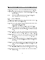
This normal-duty cycle is controlled by the active-duty cycle which in
addition denes the percentage of the electrodes being active and not in the
high-impedance state. The following screen-shot of a measurement illustrates
the real electrode behavior.
33
2.5. DESIGN WINDOW
CHAPTER 2. USER-INTERFACE
The normal-duty cycle is set to 60% meaning that the electrodes will
have the potential they have been specied with in 60% of the referencecycle period of about 15ms.
After 60% of the reference-period is over the
polarity of the electrodes is inverted. The active-duty cycle in addition is set
to 70% meaning that 70% of the reference-period the electrodes are active
and in the rest of the 30% the electrodes are switched to tristate. See the
explanations in the screen-shot shown above.
With the buttons on the right-hand side of this window the current output
voltage of the FPGA can be specied. Furthermore a reload of the FPGA
can be initiated and a check for successful loading the FPGA can be issued.
When the FPGA is successfully loaded and the FPGA-Ver button is pressed
a message is printed in the Xterm window showing the current loaded version.
After seeing this message the FPGA is fully functional and the BioModule
can be accessed.
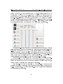
2.5.3 Level-one elements control
Level-one elements represent the next higher level in the hierarchy of
possible control-structures.
Several dierent types can be specied, of which currently seven are possible: the spreader, catcher, neuron, trap, trigger, barrier and general. The
34
2.5. DESIGN WINDOW
CHAPTER 2. USER-INTERFACE
general idea of these level-one elements is to provide a layer of control. These
level-one elements are constructed such that they can be combined to regulatory networks. The connection between these level-one elements is realized
purely in software.
Physical delays of remote elements can be dealt with.
Additionally, several timeout-features are available to allow for the buildup
of robust regulators.
All known level-one elements in this design are shown in a simple list.
A graphical representation of the connections is not yet available.
A new
element can be created, sensors and actors can be added as long as not
all requirements are fullled. Note: Before you can dene a new level-one
element you rst have to select (means highlighting) a sensor which should
be part of the level-one element. The buttons 'Put' and 'Pop' are currently
not implemented.
When pressing the 'Properties'-button a popup-window of the following
type appears.
35
2.5. DESIGN WINDOW
CHAPTER 2. USER-INTERFACE
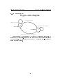
The upper section of the 'Properties'-window (left image) shows the sensors chosen for this particular level-one element: a spreader. As is shown in
more detail in section 4.1.7, two sensors and three actors have to be specied.
In the picture above only two actors are specied yet at the left image and
no actors in the right image. For each sensor an intensity value can be specied at which the sensor tells the level-one element that the existence of the
ON-condition is fullled and a second intensity-value can be specied below
which the sensor activates the OFF-condition. The sensors' intensity values
are dimensionless and relative to a reference value which can be adjusted by
pressing the 'Take reference value'-button. This reference-value is simply the
average intensity of the current camera-view.
Because the sensors might have a considerable distance to the site where
the actual decision has to be made, a delay in milliseconds can be specied
after which the recognized ON- or OFF-event is evaluated in the software. If
the sensor, when it is just actively looked at (this depends on the type of the
level-one element), does not see an event in a specied time, a timeout-event
is generated and the level-one element's state-machine is reset, see section 4
for further details on how level-one elements are implemented.
Each sensor can be specied in the context of a certain lter. If the 'S'check-box is active then before a new measurement is done the according
lter is moved into the microscope-beam to assure that the measured values
are really corresponding to the parameters set. With the 'S'-box not checked
the lter-denition only has a function as commenting the context how the
intensity-thresholds have to be interpreted.
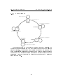
Instead of using a sensor as input another already existing level-one ele-
36
2.5. DESIGN WINDOW
CHAPTER 2. USER-INTERFACE
ment can be chosen. See an example in the right image of the gure above
where the spreader 'eeeeee' serves as input for the spreader 'qqqq'. The output of this level-one element is then taken as input for the other level-one element and provides the basis for building up networks of low-level-regulators.
2.5.4 Sequences control
Generating complex time-series of electrode-potentials can be realized with
sequence elements. To create a new sequence-element at least one actor has
to be selected (highlighted) in the design-window. Pressing the button 'New
element' pops up a window which asks for the name of the new sequenceelement.
Selected sequence elements can be switched on or o using the 'On/O 'button. Each sequence element can contain arbitrary many dierent actors.
These additional actors have to be selected and then via the button 'Add
actor' added.
Without any further specication in the according property-window of
the selected sequence-element each actor always is in the high-impedance
state.
After pressing the button 'Properties' the following window pops up in
37
2.5. DESIGN WINDOW
CHAPTER 2. USER-INTERFACE
which the user is able to dene the polarity at each discrete time step. Take
the pull-down menu below the actual electrode-names to dene the polarity
at the selected time-step.
The value 'z' means high-impedance.
Time is
running from top to bottom and the time-period is dened in the scale at
the bottom-right side, e.g. 5 seconds. This means every 5 seconds the next
step of the time-sequence is activated. After the bottom step (set) has been
executed the next time-step cycles to the top line again.
time-step (set) is done with the 'Add set'-button.
Adding a new
All electrode-potentials
are preset with the default value of high-impedance. Each selected time-step
can be removed with the 'Delete set'-button.
38
Chapter 3
Interfaces
The purpose of this chapter is to declare the many dierent interfaces available in the ng_biopro-software. It is meant as a help for developers of drivers
to attach new hardware to the ng_biopro-software. The ng_biopro-software
is written in C using an object-oriented paradigm. Thus the programming
style is a mixture between C and C++.
3.1
Hardware Interfaces
Hardware interfaces are realized with a procedure oriented set of functions.
These function headers will be declared in detail in the current section. The
naming convention is a two to three letter prex pointing to the type of
hardware (e.g.
for camera-drivers the prex is 'cam'), followed by a two
letter prex for the specic hardware (e.g.
for the Andor-camera this is
'an') and then by the procedure-name giving hints on the real functionality.
All prexes and procedure-names are connected via underscores '_'. Each
type of hardware has a special data-structure containing all specic details.
Local data, only relevant for the specic driver, has to be dened as static
in the drivers source-le, as long as this static-declaration does not interfere
with multiple driver-instantiations.
In these type-specic data structures
each function has an entry-point which is used by the ng_biopro-software to
operate the hardware. An initialization function has to be provided by the
hardware-interface which initializes the data structure with the appropriate
procedure calls.
All procedures are to be of type integer with a '-1'-return indicating an
error-condition.
This error-condition usually lets the program stop with a
series of error-messages indicating the cause of this error. Return-codes less
then '-1' indicate warnings which are not further evaluated but can be used
39
3.2. DPD-INTERFACE (DISSIPATIVE PARTICLE
CHAPTER
DYNAMICS)
3. INTERFACES
for self-test purposes.
In addition, when obeying the rules, user-interactions can be modied.
Simple buttons, scales, popup-windows and so on are available, see section
3.6.2 for further denitions.
3.2
DPD-Interface (dissipative particle dynamics)
The purpose of the DPD-interface is to allow an intimate connection between the experimental Omega-machine and a simulation-tool, in this a case
Dissipative Particle Dynamics which is a mesoscale simulation system.
Of
course, any other molecular dynamics code or partial dierential equationsystem would t as well.
The role of the ng_biopro-software is two-fold:
rstly to give the simulation-code the ability to operate the Omega-machine,
especially creating a loop between observation (camera-output) and actuation (electrode-control).
This would allow an informed feedback-loop with
the simulation providing the none-observable details and knowledge of the
chemistry going on in the micro-uidic system. The second purpose of this
interface is to provide the simulation with the exact geometric and experimental details of the experiments. This is especially useful if the simulation
tries to incorporate phase-boundaries and inhomogeneous geometries.
40
3.3. CLIENT-SERVER INTERFACE
CHAPTER 3. INTERFACES
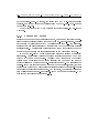
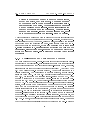
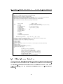
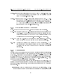
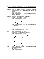
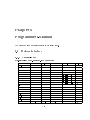
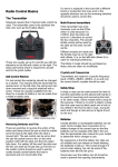
Definition of biopro−simulator interface by U. Tangen and T. Maeke (2004.09.15 − rev. 1.07)
Messages are ASCII−strings with items separated by blanks
String−constants are enclosed in quotation−marks
Parameters not being numbers are intepreted as names they must not contain white space characters
All geometric values are measured in TN (ten nanometer)
All coordinates are written in tripletts (3−dimensions) embraced by round brackets
The communication is TCP−socket−based with port−number 8085
server −> client
Type:
client −> server
J = Intensity of sensor (given back)
Q = Abort communication (server goes into wait−mode)
N = new design extraction
A = area
B = body
C = channel element
E = electrode
I = fluid input
J {sensor−name} 1 {value}
O = fluid output
Q
P = polygon−element
N
Q = Quit, Abort
R = reset simulator
S = sensor
T = tag
U = surface
V = vertex
X = Finished design extraction
General message structure:
type
name nr._of_tags. {tags}
A {name} 2 {vertices, area of interest, lower left, upper right, announces a change of area}
B {name} m {surfaces constituting this body}
C {name} #i{ >0 } #o{ >0 } {input−tags} {output−tags}
E {name} k {tags}
I {name} n {tags}
O {name} n {tags}
P {name} 1 geom k {list of vertices, for a line k = 2, follow−up lines do have the same name}
Q
S {name} k {tags}
T {name] k {values of this tag}
U {name} n {polygons constituting this surface}
V {name} m+1 {size} {tags}
X
Special tags (nr. of args. arguments):
active_pol [0,1]:polarity in active puls
geom [{x, y, z}] n: n−coordinates with x, y, z defined
passive_pol [0,1,2]: polarity of non−active puls−phase
pulsewidth [%]: percentage of active electrode per puls
rate [ul/h]: flowrate of fluid
state [0,1,2]: state is zero or one or undefined
3.3
Client-Server Interface
The purpose of the client-server interface is to allow external operators (scripts)
to access the hardware and provide a full remote control of the experiments.
The interface-declaration is specied in an additional document with name
ext_interface.pdf. The communication is realized via a TCP-connection at
port 8023.
41
3.4. BIO@FOX-INTERFACE
3.4
CHAPTER 3. INTERFACES
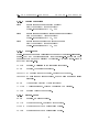
Bio@Fox-Interface
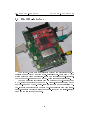
The Bio@Fox-board shown is presented without the protecting cover. It
consists of an embedded 100MHz micro-controller (Fox-board from ACME
Systems Srl) with Linux as operating-system and several hardware-interfaces.
See the hardware-manual of the Bio@Fox-board for further information.
The communication is typically done via Ethernet (RJ45-connector) and
a TCP-socket connection between the ng_biopro-software executed on the
Bio@Fox-board and the ng_biopro-software executed at the controlling PC.
Low-level communication with the Bio@Fox-board is either done via a telnetor ssh-connection or directly using the console-output at the serial-interface
ttyS0 (at the left side in the gure).
42
3.5. SIMULATION INTERFACE
3.5
CHAPTER 3. INTERFACES
Simulation interface
In addition to the control and execution of biochemical experiments a realtime simulation capability is added. The purpose of this simulation-facility
is two fold. On the one hand it should be used to test and debug electrodeactivation patterns and state-machines because debugging them in a real
experiment can be very time consuming. On the other hand the simulation
must be fast enough to be able to run at the same time when the experiment
is done to allow an on-line comparison between simulation and experiment.
This feature should be used to extract parameters from the experiment which
are otherwise not seen.
Here simulation is used as a world-model of the
experiment.
The simulation output is realized as a specic camera which is treated like
a real camera. This simulation-camera provides a comprehensive preferencesection to allow for the adjustment of all possible simulation parameters. The
simulation is particle based and particles are assumed to have no inertia. It is
quasi-three-dimensional, meaning all forces are calculated in two dimensions
and the third dimension is thought to be so shallow that eects of the third
dimension can be neglected.
Particles are mass-less and point-like but do have a charge. They do diffuse in this pseudo-three-dimensional space. As in DPD interaction forces are
only calculated up to a cut-o radius. Electrostatic forces are not restricted
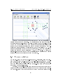
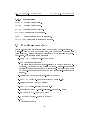
in this way because they are typically long-range. The simulation cockpit is
shown in the following picture:
In the following the dierent features of the simulation cockpit are explained:
When seeding new particles they are subjected to the parameters given in
the top part of the simulation cockpit. The Density is specied along the volume given by SX*SY*SZ. The volume is located in camera-coordinates at (X,
43
3.5. SIMULATION INTERFACE
CHAPTER 3. INTERFACES
Y, Z). The hydrophilicity is specied by Phil. and the mobility by Mobility.
These values are not specied in physical terms but as relative factors to the
programmed-in ones. Though the particles are essentially point-like the are
attached with a diameter and height (Diameter and Height, again arbitrary
units) to better distinguish between them. The diusion rate can be specied
with Di. rate. There is also the notion of single particles which are spatially
extended and which are realized as closed polygons. These spatially extended
particles, c.f. droplets, can container other point-like particles. The size or
area of these at spatially extended particles can be specied by Size. The
number of edges of the surrounding polygon by Nr. edg.. Point-like particles
are seeded by pressing the Seed-button and spatially extended particles by
pressing the Single-button.
When a sensor is activated before seeding then point-like particles are
seeded inside the sensors-area, without an activated sensor these particles
are seeded in the volume specied in the top row of the simulation cockpit.
If point-like particles are seeded directly after the denition of an extended
droplet these particles are conned to the inner part of the closed polygon. With that feature it is possible to ll droplets with certain point-like
particles.
Particles cannot cross channel-boundaries.
Channels (from the
uidics-design) are drawn when button Channels is pressed.
There are further system-wide parameters which specify interactions between the particles. These interactions are not specically intended to mean
something but should demonstrate in the simulation how the particle clouds
would possibly react if such interactions are in eect.
if their distance (c.f.
Two particles repel
the virtual disk-like shapes of particles with a given
diameter) drops below a certain value, which is in case of a hysteresis factor
(Hyster) of 1.0 equal zero. How strong this repelling force is, is specied via
the parameter Repell. Attraction on the other hand is sensed by the particles
if the are located within a cuto-radius (CutO ). The average particle size
is multiplied by the cuto-factor and gives the cuto-radius. With a virtual
temperature (Temp) a random term is added to the movement of particles
due to Brownian motion.
The most important parameter is the strength of the electrostatic forces
on the movement of the particles (Electro). This again is a relative quantity
here. The higher the number the stronger the forces are and the more severe
artifacts become. The smaller the value the longer a simulation has to run
to see any eects of the electrostatics.
The last section 'Microscope control' is not yet implemented and will
eventually be dropped because feedback-controllers now specify themselves
where the camera in the reactor should look at.
44
3.6. THE SCRIPTING-INTERFACE
3.6
CHAPTER 3. INTERFACES
The scripting-interface
Scripts are low-level ASCII-les which specify or control certain aspects of the
ng_biopro-software. These scripts are also used to add further programming
control to the experiments. Furthermore they are used to executed certain
self-test features to allow for a checking of the software as well as hardware.
3.6.1 Initialization of system and attached hardware
init_base: Specify the ASCII-data-base to be used (init_base "close.Vbase").
init_contr: Initialize control-structures for level-one elements.
init_olympus: Initialize the connection to the Olympus-control tableau (init_olympus
micoly dyck:8087 # Must be before wheel and xyz-table).
eval_xcs:
Establish the connection to the Fox-board.
init_fan:
Initialize the fan to be control by the Fox-board.
init_temp: Initialize a temperature-control system (init_temp biofox A low_temp).
init_aotf:
Initialize the acusto optical lter (init_aotf oxyus Laser /dev/ttyUSB6).
init_light: Initialize a light-source (init_light biofox blue 0 63 0).
init_pump: Initialize pumps and specify the serial devices (init_pump mmt
2 /dev/ttyS2 /dev/ttyS3).
init_xyz:
Initialize the xyz-table axes (init_xyz olympus x none # {name}
{device searched for} {number of positions}).
init_wheel: Initialize the lter-wheel (init_wheel olympus emission none "1-" "528sem" "-3-" "700ahf" "-5-" "605ahf ?" "-7-" "-8-" "585sem?"
"-10-").
eval_camera: Specify default parameters for the camera (eval_camera ext_trig).
eval_check: Self-test facility to check the graphical basic primitives.
eval_cycle: Cycle low-level electrode settings in shift-register mode.
eval_exec: Execute a script after n-seconds.
eval_external: Allow the external handler to be used (port 8023 is opened).
45
3.6. THE SCRIPTING-INTERFACE
exo:
CHAPTER 3. INTERFACES
Export objects from the internal data-base.
eval_pattern: Realize a certain electrodes' pattern and activate these electrodes with the low-level commands.
3.6.2 Graphics
eval_plot: Create a major design-window, this call requires all initializations
to be done.
eval_traces: Specify the current traces-specication from the electronics design
(eval_traces ~/bioenv/design/uidic/biopro61_std/M3_B5_CIF.dat).
eval_channel: Specify the les for the uidic-channels in the design
(eval_channel ~/bioenv/design/uidic/biopro61_std/M1_B5_SEG_CDZ.dat)
eval_nets: Specify the nets or wiring in the design
( eval_nets ~/bioenv/design/electric/biopro61/B5_NETS.dat).
eval_pins: Specify the pins or electrodes in the design
( eval_pins ~/bioenv/design/electric/biopro61/B5_PIN.dat).
eval_mark: Specify the markers in the design
( eval_mark ~/bioenv/design/electric/biopro61/B5_MARK.dat).
eval_cif:
Specify the uidic-design to be used
(eval_cif ~/bioenv/design/uidic/biopro61_std/M3_B5_CIF.dat).
eval_path: Specify the paths-le to be used
(eval_path ~/bioenv/design/uidic/biopro61_std/M3_B5_PATH.dat)
3.6.2.1 Commands to specify state-machines.
nr_states: Give the number of states the following state-machine table should
have.
add_state: Add a state to the state-machine.
add_sequence_pat: Add an arbitrary pattern to a sequence which can then
be used in the sequence-control.
add_sequence_set: Add a new set to a sequence in the sequence-control.
set_sequence_para: Specify sequence parameters.
46
3.6. THE SCRIPTING-INTERFACE
CHAPTER 3. INTERFACES
set_sim_para: Specify simulation parameters.
set_sensor: Specify the details of a sensor, timeouts and thresholds.
set_sequence: Create a new sequence.
wait_for_sim: Wait for a simulation-command to nish.
3.6.2.2 Controlling the graphical interface
eval_adjust: Attach the button to adjust camera-view with design-view.
eval_aotf: Attach the button to control the AOTF (synchronization of laserexcitation with image-grabbing).
eval_control: Attach a button for specifying and controlling the level-one
elements.
eval_log:
Attach a button to open a text-editor for logging purposes.
eval_measure: Attach a button to specify and control measurement proles.
eval_program: Attach a low-level program button to the design-window.
eval_pumps: Attach the button for specifying and controlling the pumps.
eval_sequ: Attach the button to control and specify electrode sequences.
eval_series: Attach the button the control and specify long term measurement series.
eval_shift: Attach the button to operate electrodes in low-level mode.
eval_snap: Attach the button to create camera snapshots.
eval_stream: Attach the button to create streaming videos.
eval_temp: Attach the button to control temperatures.
eval_test:
Attach the button to test the user-interface.
eval_video: Attach the button to create video sequences.
eval_xyz:
Attach the button to control the position of the xyz-table.
press_cont_but: Press the button for controlling level-one elements.
press_sequence_but: Press the button for controlling sequences.
47
3.6. THE SCRIPTING-INTERFACE
CHAPTER 3. INTERFACES
press_shift_but: Press the button for controlling electrodes at low-level.
press_sim_but: Press the button for the simulation cockpit to be used
(press_sim_but Electrodes # Press the electrodes-button in simulation cockpit).
zoom:
Zoom into a certain region in the camera- or design-window
(zoom Microscope 698 1353 162 147).
3.6.3 Feedback-control
A low-level feedback-control is specied here. Simple programs can be created and executed via the graphical-interface.
add_program: Add a new program which is a collection of further commands
which are sequentially processed.
add_program {script-name} or
add_program {name} {list of task-names, see section 3.6.5}
control_add: Add an instance of a controller. Only the name, type and a rst
or central electrode is specied (control_add revshift1 "general"
r115).
control_add_init: Add a command which is executed in case the specied
instance is activated (control_add_init $1 "move_xy sen_$5").
control_add_end: Add a command which is executed in case the specied instance is about to end its action (control_add_end $1
"move_ori").
control_high: Set the following electrodes to a high-potential for shielding
purposes when this controller-instance is active (control_high $1
r115 r117).
control_low: Set the following electrodes to a low-potential for shielding purposes when this controller-instance is active (control_low $1 r115
r117).
control_ng_biopro_extern.hgroup: Group a set of electrodes together which
are activated it this group is activated (control_group $1 0 $2 $3).
control_reference: Specify a group of sensors which are taken for building a
reference value.
48
3.6. THE SCRIPTING-INTERFACE
CHAPTER 3. INTERFACES
control_sensor: Specify all sensors which can be used by a level-one element.
The number of sensors must coincide with the required number
given by the level-one element.
control_neigh: Extract the n-th neighboring electrode in the path. A positive number means n-electrodes in direction of the path and a
negative number n-electrodes back. (control_neigh autoshift1 3 # take third electrode before central one, 'autoshift1' is the
instance name of the level-one element).
3.6.4 Controlling attached hardware
move_back: Move back with the xy-table to the last known position.
move_ori: Because moving the xy-table is not always exact in the sens of the
camera-view (the BioModules are not perfectly aligned always)
this command allows to move back to the original position when
the alignment between camera- and design-view was done.
move_xy:
Move the xy-table to the center of a given electrode. This command is used to move the camera to the region of interest.
set_pin:
Control the polarity and activity of a pin or electrode.
This
pin is activated permanently until a new command is executed.
Typically this command is used for the denition of shielding
electrodes.
3.6.5 Programming
Programming the experiments can be done at dierent levels of abstractions.
The lowest level has already been described in section 3.6.3. With the command 'add_program' a xed sequence of script-commands is executed with
no ability to adapt to the context of the running experiment. All exibility
is retained in the state-machines with their feedback-control as such. There
are no higher level constructs like a 'target'.
The next higher level in programming is described in the following. The
programmer is no longer required to specify each electrode and sensor to be
used in advance. Furthermore, more concepts are introduced and described
in the sequel.
Instance :
Most important is the concept of an 'instance'.
An in-
stance here eectively means a cluster of particles or molecules or entire
49
3.6. THE SCRIPTING-INTERFACE
CHAPTER 3. INTERFACES
droplets or containers which are of interest to host a chemical reaction
or to be moved to a new destination.
Such a cluster (chemtainer)
need not be a sharp description of something and it is the duty of
the state-machines to suciently distinguish the chemtainer from its
environment. Because of this fuzziness in the microuidic world no basic functions like 'sin' or 'cos' in classical programming languages have
been dened. Only state-machines serves as equivalents to these basic
library functions.
These are not specied further in the higher-level
language but are thought to be atoms.
Thus it becomes a question
of convenience which part of an algorithm is encoded inside a statemachine and which part is encoded at language-level. Concretely, this
means that each instance is a name and a script behind which species the local behavior of this instance.
This script must be written
such that it is independent of the specic location of this instance. To
simplify things, an instance is always thought to be a one-dimensional
structure with a central electrode and all other aected electrodes specied relative to this electrode.
Execution : The execution of an instance means activating this script
behind the name of the instance.
The commands are processed and
the state-machine is launched and nishes with a specied return code,
see section 3.6.5.5. After returning, several status-variables, see section
3.6.5.4, are available to further determine the next optimal step to
be done in the program.
These status-variables can be read by the
program as long as they are overwritten by new values.
be assigned (
assign -command)
They can
to variables and then used as long as
required.
Path : A path is a connection between two electrodes. Each path has
a working position which can be moved back and forth.
Task :
All commands inside a task are executed in sequential order.
Also blocks- and sub-blocks are treated sequentially.
But arbitrary
many tasks can be specied. These tasks are processed in a pseudoparallel fashion.
True parallelism cannot be used here because the
single available camera has to move to the regions of interest (ROI)
and these ROI might reside far apart from each other (in principle, the
system could determine whether two or more tasks t into the eldof-view of the camera but this is a software-technically dicult task
and will be postponed). To sustain a sucient quality of uorescent
yield the eld of view cannot be made arbitrary large. This means that
50
3.6. THE SCRIPTING-INTERFACE
CHAPTER 3. INTERFACES
after a command nished in task A, task B is selected and the next
command in that task is executed.
Variables :
Variables are instantiated after rst naming them in the
assign command. Status-codes, see section 3.6.5.4, can be assigned to
variables as well as other variables. Basic arithmetic operations can be
realized also as part of the assign-command.
Block :
A block starts with the begin-command and nishes at the
end-command.
A block can contain arbitrary many sub-blocks.
All
commands in a block are processed in a sequential order. A block is a
mere syntactical concept and has no physical counter-part.
Conditions :
Three basic conditions are available, GT, GE and EQ.
Comparing dierent types with each other is done implicitly if supported, otherwise an error-message is issued.
3.6.5.1 Initialization
instance:
Initialize a new instance.
instance {name} {script-le} {central electrode}
Formally instance is a name associated with a script-le and a
dened central electrode. This instance can move along a series
of electrodes.
3.6.5.2 Commands
append:
Append an element to a path and return the enlarged path.
append {path-name} {new electrode}
Status-codes returned: ERR, VALUE (the identier of the enlarged path)
assign:
Assign a value to a variable, this can be a return-value.
assign {new variable-name} {value, variable or simple algebraic
expression}
Status-codes returned: ERR, VALUE
aveinten:
Return the average intensity of sensors specied in a path. Sensors are thought to be attached to the electrodes and its names
are derived from the electrodes in the path.
aveinten {path-name}
Status-codes returned: ERR, VALUE (the average intensity)
51
3.6. THE SCRIPTING-INTERFACE
avetime:
CHAPTER 3. INTERFACES
Return the average execution time between two consecutive movements along a path. This time is updated via the move-command.
avetime {path-name}
Status-codes returned: ERR, VALUE (the average execution time
in milli-seconds)
begin:
Begin a block, this is a syntactic beginning.
begin [{name}]
Status-codes returned: none
break:
Leave the current loop.
break
Status-codes returned: none
car:
Return the rst element in a path and remove it from the path.
car {path-name}
Status-codes returned: ERR, VALUE (the identier of the rst
element)
cdr:
Remove the rst element of a path and return the remaining path.
cdr {path-name}
Status-codes returned:
ERR, VALUE (the identier of the re-
maining path)
cons:
Insert a rst element into a path and return the enlarged path.
cons {path-name} {new electrode}
Status-codes returned: ERR, VALUE (the identier of the enlarged path)
cur:
Return or set the current element in a path.
Electrode-name
or identier must be part of given path, otherwise an error is
generated.
cur {path-name}
[{electrode-name or id}]
Status-codes returned: ERR, VALUE
do:
Loop as long as no break occurs.
do
Status-codes returned: none
ele:
Return the la certain element of a path, the path remains unaffected.
last {path-name} {index in list, beginning from 0}
Status-codes returned: ERR, VALUE (the identier of the certain element)
52
3.6. THE SCRIPTING-INTERFACE
elif:
CHAPTER 3. INTERFACES
Check a Boolean variable if the earlier check failed.
elif {function with Boolean return or condition}
Status-codes returned: none
else:
Execute a block in case all checks failed before.
else
Status-codes returned: none
end:
End that block.
end [{name}]
Status-codes returned: none
enddo:
End of loop.
enddo
Status-codes returned: none
endif:
The if-construction is nished.
endif
Status-codes returned: none
endtask:
End of the specication of that task.
endtask [{name}]
Status-codes returned: none
exec:
Execute an instance with a target as parameter.
exec {name}
Status-codes returned: COLL, END, ERR, NEXT, TIMEOUT,
TIMEERR
if:
Check a Boolean variable.
if {function with Boolean return or condition}
Status-codes returned: none
last:
Return the last element of a path, the path remains unaected.
last {path-name}
Status-codes returned: ERR, VALUE (the identier of the last
element)
location:
Return the current location.
location
Status-codes returned: ERR, VALUE
maxinten:
Extract the sensor with the maximum intensity.
maxinten {List of sensors to be checked}
Status-codes returned: ERR, VALUE
53
3.6. THE SCRIPTING-INTERFACE
maxtime:
CHAPTER 3. INTERFACES
Return the maximum execution time between two consecutive
movements along a path.
This time is updated via the move-
command.
maxtime {path-name}
Status-codes returned: ERR, VALUE (the maximum execution
time in milli-seconds)
mininten:
Extract the sensor with the minimum intensity.
mininten {List of sensors to be checked}
Status-codes returned: ERR, VALUE
mintime:
Return the minimum execution time between two consecutive
movements along a path.
This time is updated via the move-
command.
mintime {path-name}
Status-codes returned: ERR, VALUE (the average execution time
in milli-seconds)
move:
Move the instance to the electrode given in the current pathelement.
move {name of instance} {path-name}
Status-codes returned: COLL, END, ERR
next:
Return the next nth-element in a path.
next {path-name} [{nth position, 0 = current}]
Status-codes returned: ERR, VALUE
nr:
Return the number of elements in a path.
nr {path-name}
Status-codes returned: ERR, VALUE (number of elements)
path:
Specify the target electrode, where the instance should walk to.
path {name of path} {rst electrode} {second electrode name}
Status-codes returned: ERR
prev:
Return the previous nth-element element in a path.
prev {path-name} [{nth position, 0 = current}]
Status-codes returned: ERR, VALUE
task:
Create a new process task which is running in pseudo parallel
mode with other tasks.
task [{name}]
Status-codes returned: ERR
54
3.6. THE SCRIPTING-INTERFACE
CHAPTER 3. INTERFACES
3.6.5.3 Testing conditions
iseq:
Is rst operand equal to second operand?
iseq {rst operand} {second operand}
Status-codes returned: COND, ERR
isge:
Is rst operand greater or equal than second operand?
isge {rst operand} {second operand}
Status-codes returned: COND, ERR
isgr:
Is rst operand greater than second operand?
isgr {rst operand} {second operand}
Status-codes returned: COND, ERR
3.6.5.4 Status-codes
Status-codes are temporary variables which are set by function-calls as sideeects. They may be overwritten from every function-call. If they are to be
permanent they have to be assigned to variables. Not every status-codes is
set by any function-call.
COLL:
Boolean, a collision of two instances is detected.
END:
Boolean, the instance is nished.
TIMEOUT: A warning timeout occurred, waiting took too long.
TIMEERR: A real timeout error occurred, which means something failed
seriously.
ERR:
Was an error detected by last execution?
VALUE:
A value is returned, this can be assigned to a variable.
COND:
Boolean value of true or false.
3.6.5.5 Return-codes
ERR:
Boolean, an error occurred.
OKAY:
Everything is okay, continue with execution.
FALSE:
Everything okay but Boolean value of false.
TRUE:
Everything okay but Boolean value of true.
55
3.7. RUNTIME-PARAMETERS
CHAPTER 3. INTERFACES
3.6.5.6 Special values
FALSE:
Boolean value of false.
TRUE:
Boolean value of true.
REACTOR: Instance is at a reactor.
JUNCTION: Instance is at a junction.
PIN:
Instance sitting above an electrode.
CHANNEL: The instance is sitting in a channel.
3.7
Runtime-parameters
Runtime-parameters are specied using the standard Unix-convention.
A
minus-sign plus the type of the parameter, then a blank and the parameter
value following.
Strings containing blanks have to be enclosed in double-
quote-signs. The available parameters are:
-batch {#s = Actual batch-le to be taken}
-cam {an integer value} [0]
This parameter denes the camera-interface to be used for image acquisition.
Depending on the version of the ng_biopro-software used
dierent types of cameras can be operated with. Use value 0x10 when
an Andor-camera is attached and 0x20 if a Vosskuehler-rewire camera
is used.
-design {name of the BioModule-design to be used}
-dev {#n = MereGen-Hardware device to be used [0..3]}
-display {name:0 = Set X11 display}
-env {#s = Design-environment path [./]}
-uid {'str' = BioPRO-uidic-design [e.g. segmented_ow]}
-fox {name of FOX-board to be used}
-mmt {name of MMT-pumps to be used}
-ni
Non interactive mode
56
3.8. DESIGN ENVIRONMENT DETAILS CHAPTER 3. INTERFACES
-ng
Non graphical mode
-np {#p = Number of pumps to be used [1..p]}
-par
Parallel-port should be used
-path {Dene NGEN search path}
-pref {#s = Preference le [~/.ngen]}
-run {#n = running number of experiment}
-sim
Allow simulator to connect to program
-srv
Go into server-mode
-tok {#k = MereGen-Card where to run the program}
-tse
TSE-pumps shall be used
-tst
Test-pumps shall be used
-xcs
Test mode for XCS functionality
3.8
Design environment details
57
Chapter 4
Level-One
Level-one elements are basic feedback-controllers. Their main purpose is to
linearize the unpredictable uorescence intensity output of chemical reactions
or of the movement of uorescing molecules.
The structure of these basic
controllers is the following: they are state-automata with electrodes as output
and sensors as input. In addition, a state also can be used as an output to a
follow-up further level-one element. Actors or electrodes are simply activated
or not.
Not so simple are sensors. In the current version of the biopro-software
sensors are essentially two-point threshold devices with two binary outputs:
the rst output is a transient ag which is set if the upper threshold of
the sensor has been surpassed by measured uorescent intensity. The second
generated output again is a transient ag which is set if the lower threshold is
checked by a decreasing level of measured uorescence. In this way regulators
can be created which are based on a two-point sampling controller.
It would have been easy to create also more classical regulators like PI or
PID controllers but the extreme uctuations of molecules and uorescence
intensities made it more suitable to look for more robust controller concepts.
Even with this simplied sensor-concept several parameters have to be
adjusted in a typical experiment: The two, upper and lower, thresholds have
to be specied, a delay-time, which denes when the event should be reported
to the state-machine has to be given and a timeout parameter which tells
the state-machine that this sensor is no longer in its desired working point.
Furthermore, especially the thresholds are to be thought of as dynamically
adapting, probably changed by certain states of the state-machine.
It can
also be specied if certain lters have to be set before a measurement is made.
58
4.1. BASIC ELEMENTS
4.1
CHAPTER 4. LEVEL-ONE
Basic elements
Seven basic elements have been specied so far: barrier, catcher, general,
neuron, spreader, trap and trigger. Each of them tries to implement certain
isolated functionalities.
4.1.1 BARRIER
Barrier−state−diagram
some material detected
Wait for event to start
0
concentration at (4) still to high
base state
1
repell
pickup and transport back
2
still material in the line
The barrier, which state-diagram is shown above, should prevent molecules
from surpassing that barrier. Of course, this only can be done with certain
limits. If too many molecules are to be repelled the capacity of this barrier
is reached and the molecules have to be released again. This special event
can then be used by a following level-one element to do its processing.
59
4.1. BASIC ELEMENTS
CHAPTER 4. LEVEL-ONE
4.1.2 CATCHER
Catcher−state−diagram
e0 = tri
e1 = tri
some material (negatively charged) detected
Wait for event to start
e0 = 3.3V
e1 = 0V
l0
s0 < s0l
concentration at sensor s0 in the
supply channel is not sufficient
base state
concentrate
e0 = tri
e1 = tri
l1
s1 < s1u
e0 = 3.3V
e1 = 0V
x = concentration of labeled molecules
e0 = electrode next to molecule supply
e1 = electrode next to e0
s0 = sensor in supply channel f0(x)
s1 = sensor in concentration channel f1(x)
e0 = 0V
e1 = 3.3V
l2
transfer
s1 > s1l
concentration at sensor s1 is not sufficient
e0 = 0V
e1 = 3.3V
s0l = lower threshold (10%) of sensor in supply channel
s0u = upper threshold of sensor (90%) in supply channel
s1l = lower threshold of sensor (10%) in concentration channel
s1u = upper threshold of sensor (90%) in concentration channel
The catcher is similar to the barrier the only dierence is that it should
concentrate as many molecules as possible at an electrode.
If a sucient
number of molecules have been gathered or attracted then the bulk is transferred to a new location and state sending a signal to a follow-up level-one
element.
4.1.3 General
As the name implies this level-one element species a general state-machine
which can encompass all other level-one elements described in this section.
Several specic commands are provided to describe such a state-machine in
detail, see section 3.6.3.
60
4.1. BASIC ELEMENTS
CHAPTER 4. LEVEL-ONE
4.1.4 Neuron
The neuron is not yet implemented.
It is dierent to the other level-one
elements because is allows several sensors to be utilized as input for one single
state. As with neurons common, the sensor outputs, in our case spikes, are
integrated of a certain span of time and if a threshold is reached then the
following state is activated. It is easily imaginable how intriguing experiments
with chemical neurons could be devised.
4.1.5 TRAP
The trap
Wait for event to start
some material detected
0
base state
concentration at (4) not sufficient
signal to following stage that material is free
release
concentrate
1
4
material not yet released
concentration at (3) not sufficient
transfer back
transfer
2
3
concentration at (2) not sufficient
The trap is similar to the catcher the only dierence is that it should
catch as many molecules as possible between two electrodes.
This is done
by oscillating the electrodes. The capacity, in terms of numbers of molecules
caught, is probably larger then with the catcher which only has one electrode
to concentrate the molecules.
61
4.1. BASIC ELEMENTS
CHAPTER 4. LEVEL-ONE
4.1.6 TRIGGER
Trigger−state−diagram
some material detected
Wait for event to start
0
concentration at (4) not sufficient
base state
concentrate
1
signal to following state that event happened
Trigger serves as the initiator of a network of level-one elements.
It
switches to the signaling-state if a sucient high or low concentration has
been measured. This signal is then taken up by a following level-one element
as its activation signal.
62
4.1. BASIC ELEMENTS
CHAPTER 4. LEVEL-ONE
4.1.7 SPREADER
Wait for event to start
some material detected
0
base state
concentration at (4) not sufficient
split
concentrate
1
4
concentration at (3) not sufficient
concentration at (3) not sufficient
force apart
transfer
2
3
concentration at (1) not sufficient
The spreader should try to separate mixtures of charged molecules. The
idea is that small molecules can be moved faster through a uid or a gel then
larger molecules.
The spreader accumulates material at one location and
if the concentration surpasses a threshold then a grabber electrode tries to
capture as much material as possible until again a certain threshold has been
surpassed.
After this threshold the spreader stops action and a following
stage can take over.
63
4.2. NETWORKS
4.2
CHAPTER 4. LEVEL-ONE
Networks
some material detected
Wait for event to start
0
concentration at (4) not sufficient
Trigger
base state
concentrate
1
signal to following state that event happened
some material detected
some material detected
Wait for event to start
Wait for event to start
0
0
concentration at (4) not sufficient
base state
concentrate
1
1
repell
Catcher
transfer
concentration at (4) still to high
Barrier
base state
2
pickup and transport back
2
concentration at (3) not sufficient
still material in the line
Wait for event to start
Wait for event to start
some material detected
some material detected
0
0
base state
base state
concentration at (4) not sufficient
signal to following stage
that material is free
release
concentrate
concentration at (4) not sufficient
split
1
4
concentrate
1
4
Trap
material not yet released
Spreader
concentration at (3) not sufficient
concentration at (3) not sufficient
concentration at (3) not sufficient
transfer back
force apart
transfer
2
transfer
3
2
3
concentration at (2) not sufficient
concentration at (1) not sufficient
Networks of level-one elements can be build using states of level-one elements as replacement for sensors. If this state is entered a signal is issued
to the following level-one element which is equivalent to reaching the upper
threshold of the sensor. It this state is left again a signal is issued which is
equivalent to underpin the lower threshold.
64
Chapter 5
Programmers-Manual
The programmers manual is currently in an infant state.
5.1
Drivers interface
5.1.1 Parallel-port
Pin-assignment of PC-parallel-port to adapter
Signal Name
Register Bit
DB-25 Pin
I/O Direction
Board-BioPRO
G88-40
-Strobe
+Data Bit 0
+Data Bit 1
+Data Bit 2
+Data Bit 3
+Data Bit 4
+Data Bit 5
+Data Bit 6
+Data Bit 7
-Acknowledge
+Busy
+Paper End
+Select In
-Auto Feed
-Error
-Initialize
-Select
Ground
D0
D1
D2
D3
D4
D5
D6
D7
S6
¬S7
S5
S4
¬C1
S3
C2
¬C3
-
1
2
3
4
5
6
7
8
9
10
11
12
13
14
15
16
17
18-25
Output
Output
Output
Output
Output
Output
Output
Output
Output
Input
Input
Input
Input
Output
Input
Output
Output
-
GCK5
TMS
TDI
TCK
-|>| Vcc-+
-|>| Vcc-+
-|>| Vcc-+
-|>| Vcc-+
-|>| Vcc-+
30
25
26
27
37,39
TDO
28
/Prog
/Init
CClk
DIN
GND
22
21
23
24
29,40
¬C0
65
5.1. DRIVERS INTERFACECHAPTER 5. PROGRAMMERS-MANUAL
VCC at adapter GP1 = ST53 or GP3 = ST55 to ST62 connected
S7, C0, C1 & C3 signals are inverted
Initial state of port is Dat=0xff Sts=0x7f Ctl=0xf Flags = 0x0 Phase =
0x1
typedef struct s_ng_parport ng_parport; /* Data of parallel-port-class */
typedef int (*pa_port_info)(void);
typedef int (*pa_set_all)(int);
typedef int (*pa_set_din)(int);
typedef int (*pa_set_prog)(int);
typedef int (*pa_set_cclk)(int);
typedef int (*pa_set_gck5)(int);
typedef int (*pa_set_tms)(int);
typedef int (*pa_set_tdi)(int);
typedef int (*pa_set_tck)(int);
typedef int (*pa_set_vcc)(int);
typedef int (*pa_get_init)(void);
typedef int (*pa_get_tdo)(void);
typedef int (*pa_get_tms)(void);
struct s_ng_parport {
NG_OBJECT_HDR /* p_data>p_ana, p_user>? */
pa_port_info f_port_info; /* Printout some information of parport */
pa_set_all f_set_all; /* Set all parport pins to value x */
pa_set_din f_set_din; /* Set DIN of FPGA */
pa_set_prog f_set_prog; /* Pull the PROG-pin and initialize FPGA */
pa_set_cclk f_set_cclk; /* Set the CCLK to value x */
pa_set_gck5 f_set_gck5; /* Set the global clock 5 GCK5 to x */
pa_set_tms f_set_tms; /* Set TMS (at FPGA) to value x */
pa_set_tdi f_set_tdi; /* Set TDI (at FPGA) to value x */
pa_set_tck f_set_tck; /* Set TCK (at FPGA) to value x */
pa_set_vcc f_set_vcc; /* Activate power-supply via parport */
pa_get_init f_get_init; /* Get INIT-pin status */
pa_get_tdo f_get_tdo; /* Get value of TDO at FPGA */
pa_get_tms f_get_tms; /* Get current TMS value */
NG_OBJECT_FOOT
};
5.1.2 Camera-driver
typedef int (*c_get_sens_bounds)(ng_ngen *, int *, int *);
typedef int (*c_set_sens)(ng_ngen *, int);
typedef int (*c_set_exposure)(ng_ngen *, double);
typedef int (*c_get_expo_bounds)(ng_ngen *, double *, double *);
typedef int (*c_rdpicqq8)(ng_ngen *, int, int, int, int, pixel8_t *);
typedef unsigned int (*c_rd_info)(ng_ngen *);
typedef int (*c_init_sum_mems)(ng_ngen *, int);
typedef int (*c_sum_clear)(ng_ngen *, int);
typedef int (*c_set_sumarea)(ng_ngen *, unsigned int, unsigned int, unsigned int, unsigned int, unsigned int);
typedef int (*c_age_wr_videoram)(ng_ngen *, unsigned int, unsigned int, unsigned int);
typedef unsigned int (*c_get_sumpixels)(ng_ngen *, int);
typedef unsigned int (*c_get_sumram)(ng_ngen *, int);
typedef int (*c_read_sumram)(ng_ngen *, int);
typedef int (*c_wr_ofs_fac)(ng_ngen *, unsigned int, unsigned int);
66
5.1. DRIVERS INTERFACECHAPTER 5. PROGRAMMERS-MANUAL
typedef
typedef
typedef
typedef
typedef
typedef
typedef
typedef
typedef
int
int
int
int
int
int
int
int
int
(*c_ioctl)(ng_ngen *, int);
(*c_min_avg_max)(ng_ngen *, int *, int *, int *);
(*c_image_size_x)(void);
(*c_image_size_y)(void);
(*c_on)(ng_ngen *);
(*c_o)(ng_ngen *);
(*c_status)(ng_ngen *, ng_grak *);
(*c_read_vbase)(Vbase *);
(*c_write_vbase)(Vbase *);
5.1.2.1 Camera data-structure
struct s_ng_cam {
NG_OBJECT_HDR /* p_data>p_ana, p_user>? */
...
c_get_sens_bounds f_get_sens_bounds; /* Get sensitivity bounds */
c_get_expo_bounds f_get_expo_bounds; /* Get bounds of exposures */
c_set_sens f_set_sens; /* Set sensitivity gain */
c_set_exposure f_set_exposure; /* Set exposure time */
c_rdpicqq8 f_rdpicqq8; /* Read an byte-image */
c_rd_info f_rd_info; /* Get info about camera */
c_init_sum_mems f_init_sum_mems; /* Initialize summen-memories */
c_sum_clear f_sum_clear; /* Clear summen-memories */
c_set_sumarea f_set_sumarea; /* Dene a summen-area */
c_age_wr_videoram f_age_wr_videoram; /* Write something into cambuf */
c_get_sumpixels f_get_sumpixels; /* Get size of summen-area */
c_get_sumram f_get_sumram; /* Get integrated value of sum */
c_read_sumram f_read_sumram; /* Read value of sum and clean */
c_wr_ofs_fac f_wr_ofs_fac; /* Dene oset factor */
c_ioctl f_ioctl; /* I/O-control */
c_min_avg_max f_min_avg_max; /* Readout min, avg and max-va */
c_image_size_x f_image_size_x; /* Return the cameras nr. x-pi */
c_image_size_y f_image_size_y; /* Return the cameras nr. y-pi */
c_on f_on; /* Switch the camera on */
c_o f_o; /* Switch the camera o */
c_status f_status; /* Present a status-window */
c_read_vbase f_read_vbase; /* Read presets from VBase */
c_write_vbase f_write_vbase; /* Store presets in VBase */
...
};
NG_OBJECT_FOOT
5.1.3 Andor-CCD
67
Chapter 6
Miscellaneous
6.1
GTK+-2-installation instructions for MacOSX and other UNIX-derivatives.
After installing XCode-Tools and X11-development-environment the following packages (all are available from public-domain-on-line-sources, e.g. sourceforge.net) need to be installed: atk-1.9.1.tar.bz2 cairo-1.2.6.tar.gz jpegsrc.v6b.tar.gz
expat-2.0.0.tar.gz libXrender-0.9.0.tar.gz libpng-1.2.8.tar.bz2 fontcong-2.4.2.tar.gz
pango-1.12.4.tar.bz2 freetype-2.1.4.tar.gz pkg-cong-0.20.tar.gz gettext-0.16.1.tar.gz
glib-2.12.12.tar.bz2 render-0.8.tar.gz gtk+-2.10.12.tar.bz2 renderext-0.9.tar.gz
ti-3.7.4.tar.gz. The revisions shown here reect the situation in May 2007.
Later revisions should be unproblematic though if not requirements are given
with the congure-scripts of the individual packages.
Unfortunately the sequence of installation is not at all arbitrary: pkgcong, gettext, expat, jpegsrc, ti, libpng have to be installed rst.
Then
follows render, libXrender, freetype and fontcong. The last chunk are glib,
cairo, atk and pango. The last package to be installed is gtk itself. In almost all packages congure-scripts are provided. Sometimes, special runtime
options have to be provided. 'congure' can always be called as : congure
help, resulting in an extensive list of options possible.
As usual, after a
successful run of 'congure', 'make' and 'make install' have to be issued. Alternatively, nk, adapt, synaptic or other software-installation utilities can
be used as well. Please be aware, that the software from the packages normally will be install in the /usr/local/.. tree whereby nk for examples uses
a /sw/.. tree. This can result in not found libraries and include-les and has
to be resolved individually.
68
6.2. REVISION HISTORY
6.2
CHAPTER 6. MISCELLANEOUS
Revision history
Version 0.1 was released in April 2006
Version 0.2 was released in May 2007 with further descriptions of hardwareinterfaces.
Version 0.4 update of manual with simulation and new feedback-system
described.
Version 0.5 added further scripting-commands.
6.3
Release Notes
69
Index
actor, 20, 21, 29, 3537, 58
Select-button, 11
sensor, 15, 17, 18, 20, 21, 2729, 35,
Fox-controller, 8, 10, 11, 42
36, 47, 49, 58, 61, 64
BioModule, 5, 7, 1013, 34, 49, 56
server-mode, 14
startbio, 6, 7, 912
Chemtainer, 50
client-mode, 14
Use existing session, 10
congure, 13
user-interface level, 9
customization, 9
xy-table, 8, 24
design, 14
design variants, 9
Download XCS, 10
DPD, 43
electrode, 5, 8, 11, 12, 14, 15, 18, 20,
21, 23, 28, 29, 3234, 37, 38,
40, 49, 51, 56, 58, 60, 61, 63
FPGA, 5, 11, 13, 18, 21, 32, 34, 66
level-one, 8, 3437, 5862, 64
Linux, 5, 6, 42
MacOS-X, 5, 6, 68
MereGen, 11, 13
navigation tool, 9
NGEN_DESIGN, 57
Perl-TK-interface, 6, 7, 9, 12, 14, 30
pin, 18, 49
pumps, 10
ReScan-button, 12
ROI, 8, 49, 50
70
Bibliography
71