1
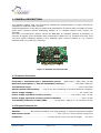
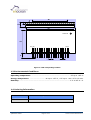
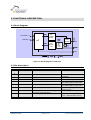
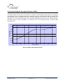
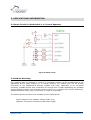
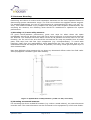
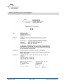
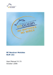
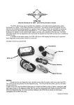
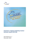
2-level Repeater Module
TCM 110
Step Code DD and above
User Manual V2.11
May 2007
Revision History
The following major modifications and improvements have been made to the initial version of
the document (TCM 110 User Manual V1.0):
Version Subject (major changes since last version)
1.1
1.2
1.3
1.4
1.5
2.0
2.1
2.11
Current consumption corrected, approval requirements modified, minor corrections
2.3 Telegram timing corrected
Declaration of conformity added
FCC/IC Approval Requirements added
Correction in current consumption.
Release for new step code DD with 2-level repeater functionality
Operation time for switching between repeater levels increased from 0.5s to 2s
Antenna drawing modified
Published by EnOcean GmbH,
Kolpingring 18a, 82041 Oberhaching
© EnOcean GmbH
All Rights Reserved
Important!
This information describes the type of component and shall not be considered as assured characteristics. No
responsibility is assumed for possible omissions or inaccuracies. Circuitry and specifications are subject to change
without notice. For the latest product specifications, refer to the EnOcean website: http://www.enocean.com.
As far as patents or other rights of third parties are concerned, liability is only assumed for components, not for
applications, processes and circuits implemented within components or assemblies.
EnOcean does not assume responsibility for use of devices described and limits its liability to the replacement of
devices determined to be defective due to workmanship. Devices or systems containing RF components must meet the
essential requirements of the local legal authorities.
EnOcean GmbH does not recommend the use of its products in life support applications and will not knowingly sell its
products for use in such applications unless it receives an adequate “products liability indemnification insurance
agreement”.
Components of the modules are considered and should be disposed of as hazardous waste. Local government
regulations are to be observed.
Packing: Please use the recycling operators known to you. By agreement we will take packing material back if it is
sorted. You must bear the costs of transport. For packing material that is returned to us unsorted or that we are not
obliged to accept, we shall have to invoice you for any costs incurred.
©EnOcean GmbH
Page 2 of 14
TCM 110 User Manual V2.11
Table of Contents
1. GENERAL DESCRIPTION________________________________________________________________ 4
1.1 Features Overview __________________________________________________________________ 4
1.2 Physical Dimensions ________________________________________________________________ 4
1.3 Environmental Conditions __________________________________________________________ 5
1.4 Ordering Information _______________________________________________________________ 5
2. FUNCTIONAL DESCRIPTION ___________________________________________________________ 6
2.1 Block Diagram _______________________________________________________________________ 6
2.2 Pin Description ______________________________________________________________________ 6
2.3 Configuration ________________________________________________________________________ 7
2.4 Received Signal Strength Indicator (RSSI) ________________________________________ 8
3. APPLICATIONS INFORMATION ________________________________________________________ 9
3.1 Basic Circuit For Switchable 1 or 2-Level Repeater _______________________________ 9
3.2 Module Mounting ____________________________________________________________________ 9
3.3 Antenna Mounting__________________________________________________________________ 10
3.4 Transmission Range _______________________________________________________________ 11
3.5 Power Supply Requirements ______________________________________________________ 11
3.6 CE Approval Requirements ________________________________________________________ 12
3.7 FCC Approval Requirements _______________________________________________________ 12
4. DECLARATION OF CONFORMITY ______________________________________________________ 14
©EnOcean GmbH
Page 3 of 14
TCM 110 User Manual V2.11
1. GENERAL DESCRIPTION
The repeater module TCM 110 of EnOcean enables the implementation of highly efficient RF
repeaters for EnOcean radio systems.
A typical application is the easy to install local optimization of system radio coverage to ensure
good radio reception behind shadowing objects or in recesses behind room corners for
example.
The TCM 110 transceiver module serves the 868 MHz air interface protocol of EnOcean. It
receives all signals of the EnOcean radio transmitters (based on e.g. modules PTM 100, STM
100) and sends refreshed signals to any EnOcean radio receiver (based on e.g. receiver
modules RCM 110, RCM 120, TCM 120).
Figure 1: Repeater module TCM 110
1.1 Features Overview
Frequency / modulation type / transmission power: ..... 868.3 MHz / ASK / max. 10 mW
Data rate (transmitter) / channel bandwidth (receiver):................. 120 kbps / 280 kHz
Transmission range: ............................................................................ 300 m free field
Signal repeater functionality: ......one or two level repeating of received EnOcean telegrams
Power supply voltage: ........................................................................... 5V +10%/-5%
Power supply operation current (receive): .............................. typ. 33mA, max. 40 mA
Power supply operation current (receive+transmit): ................................ max. 55 mA
Transmitting indication output (LED): .......... 20 mA max., approx. 3 x 2 ms within 50 ms
1.2 Physical Dimensions
Antenna:................ No antenna installed, 9 cm whip antenna or external antenna mountable
Dimensions of PCB: .......................................... 24.0 x 42.0 x 5 mm (without wiring pins)
Connector: ........................................16 pins, grid 2.0 mm (4.0 mm in length,
©EnOcean GmbH
Page 4 of 14
0.5 mm)
TCM 110 User Manual V2.11
30
2.45
5.5
1.225
Pin 16
Pin 1
42
Antenna
24
Pin 1
Pin 16
4
2
0.5
Figure 2: TCM 110 package outline
1.3 Environmental Conditions
Operating temperature: ..................................................................... -25 up to +65 °C
Storage temperature: ........................... -40 up to +85 °C, +85 up to +100 °C for 1h max.
Humidity:............................................................................................ 0 % to 95 % r.h.
1.4 Ordering Information
Type
EnOcean Ordering Code
TCM 110
S3003-K110
©EnOcean GmbH
Page 5 of 14
TCM 110 User Manual V2.11
2. FUNCTIONAL DESCRIPTION
2.1 Block Diagram
Data
LEVCONF1..2
LEVIND1..2
RF
Transmitter
TxRx
Switch
SAW
filter
MC
µC
Data
RF
Receiver
ANT
LNA
RSSI
LED
RESET
VCC
GND
Figure 3: Block diagram of TCM 110
2.2 Pin Description
Pin No.
1, 16
Symbol
GND
2
____________
5
7
8
LEVCONF1
LEVCONF2
LEVIND1
Input to set repeater level
Input to set repeater level
Output to indicate repeater level
9
LEVIND2
Output to indicate repeater level
12
LED
Transmission indicator
14
RSSI
15
VCC
Indication output of received signal
strength (peak detection)
Power supply
RESET
Function
Ground connection
Operational characteristics
External reset signal
May be left open for normal
operation
External 10kΩ pull-up needed
Internal pull-up available
1-level: HIGH, 2-level: LOW
5V CMOS output, 20mA max.
1-level: LOW, 2-level: HIGH
5V CMOS output, 20mA max.
20 mA max., approx. 3x2 ms
within 50 ms
Source impedance app. 20 KΩ
Other
©EnOcean GmbH
Page 6 of 14
5 V DC +10%/-5%, 55 mA
max. (without LED current)
Leave open
TCM 110 User Manual V2.11
VCC
4K7
RESET
100n
Figure 4: Equivalent schematics for /RESET
2.3 Configuration
The TCM 110 module implements a one or two-level repeater for EnOcean radio telegrams.
1-level repeater: If a received telegram is a valid and original (not yet repeated), the telegram
is repeated after a random delay.
2-level repeater: If a reiceived telegram is valid and original or repeated once, the telegram is
repeated after a random delay.
The repeated telegram is marked as “repeated” by an increased repeater counter.
Please note that configuration telegrams are not repeated.
Setting the repeater level:
At start-up the module the module is started as 1-level repeater.
The 2-level repeater functionality can only be activated if the external pull-up at LEVCONF1 is
available, and LEVCONF1..2 are not connected to GND at start-up of the module.
If these conditions are fulfilled the module reads the repeater level to be activated from
EEPROM. After production the 1-level configuration is stored in EEPROM.
Before each change of the repeater level LEVCONF1 and LEVCONF2 must be HIGH.
Activation of 2-level repeating: Connect LEVCONF2 to GND for >2s. LEVCONF1 must be HIGH
(pull-up) during that time. The module will then set LEVIND1 LOW and LEVIND2 HIGH and
activate the LED output for 4s. Then the new repeater level is stored in EEPROM.
Activation of 1-level repeating: Connect LEVCONF1 to GND for >2s. LEVCONF2 must be HIGH
(internal pull-up) during that time. The module will then set LEVIND1 HIGH and LEVIND2 LOW
and activate the LED output for 4s. Then the new repeater level is stored in EEPROM.
Repeater transmit timing:
The repeated signal consists of three subtelegrams as the original telegram.
Delay between received telegram and 1st subtelegram: 1 ms + n x 1 ms (integer n: 0≤n≤3)
Delay between 1st and 2nd subtelegram: 6 ms + n x 1 ms (integer n: 0≤n≤3)
Delay between 2nd and 3rd subtelegram: 18 ms + n x 1 ms (integer n: 0≤n≤11)
©EnOcean GmbH
Page 7 of 14
TCM 110 User Manual V2.11
2.4 Received Signal Strength Indicator (RSSI)
The RSSI output of the TCM 110 module is useful for transmission range tests. By indicating
the strength of an incoming RF signal, this output allows the assessment of RF link quality and
transmission range. The RSSI pin output voltage is typically 0.9 V with no RF signal, rising to
typically 2.6 V at maximum signal. The external loading should be kept to a minimum since
the RSSI output source impedance is around 20 kΩ. The following shows a typical RSSI
characteristic:
3,00
2,75
RSSI output (V)
2,50
2,25
2,00
1,75
1,50
1,25
1,00
-120
-110
-100
-90
-80
-70
-60
-50
-40
-30
-20
-10
RF input (dBm)
Figure 5: RSSI output characteristics
©EnOcean GmbH
Page 8 of 14
TCM 110 User Manual V2.11
3. APPLICATIONS INFORMATION
3.1 Basic Circuit For Switchable 1 or 2-Level Repeater
Figure 6: Basic circuit
3.2 Module Mounting
The modules may be mounted in vertical or horizontal position to the motherboard of the
application device (load module). In a vertical position, the module pins can be directly
connected to the motherboard through suitable PCB holes. Optionally or for horizontal
mounting, suitable female strip connectors for through-hole or SMD assembling are available
and are supplied ready to the required contact number (e.g. type BLY from Fischer Elektronik).
Additional module fixing may be necessary in rough environments.
The following features have to be available on the motherboard:
-
Power supply for the repeater module (GND, VCC)
-
Optional: connection to RSSI and LED output signal
©EnOcean GmbH
Page 9 of 14
TCM 110 User Manual V2.11
3.3 Antenna Mounting
Positioning and choice of receiver and transmitter antennas are the most important factors in
determining system transmission range. The TCM 110 modules are supplied without antenna.
For standard applications, the use of a whip antenna is recommended (87 mm/ 0.14 mm2 Cuwire). This antenna enables a very compact unit with good radio reception characteristics. For
mounting the antenna, the following notes should be considered to optimize the system
performance:
a) Mounting a 1/4-wave whip antenna:
For good receive/transmit performance, great care must be taken about the space
immediately around the antenna since this has a strong influence on screening and detuning
the antenna. The antenna should be drawn out as far as possible and must never be cut off.
Primarily, the far end of the wire should be mounted as far away as possible from all metal
parts, PCB strip lines and fast logic components (e.g. microprocessors). To avoid radio
frequency hash from the motherboard, which desensitizes the unit, PCB strip lines on the
motherboard should be designed as short as possible, and using a PCB ground plane layer is
also recommended.
Note that 868 MHz whip antennas do not show any directional effects under free-field radiowave propagation conditions (spot-wise radiator).
Figure 7: Specification of whip antenna ( L=89 ± 2 mm, color blue)
b) Mounting an external antenna:
For mounting the device at bad RF locations (e.g. within a metal cabinet), an external antenna
must be used. The external antenna can be connected to the equipment by a 50Ω coax feeder.
©EnOcean GmbH
Page 10 of 14
TCM 110 User Manual V2.11
3.4 Transmission Range
The main factors that influence the system transmission range are type and location of the
antennas of the receiver and the transmitter, type of terrain and degree of obstruction of the
link path, sources of interference affecting the receiver, and “dead” spots caused by signal
reflections from nearby conductive objects. Since the expected transmission range strongly
depends on this system conditions, range tests should categorically be performed before
notification of a particular range that will be attainable by a particular application.
The following figures for expected transmission range are considered by using a PTM, a STM or
a TCM radio transmitter device and the RCM or the TCM radio receiver device with preinstalled
whip antenna and may be used as a rough guide only:
•
•
•
•
•
Line-of-sight connections: Typically 30m range in corridors, up to 100m in halls
Plasterboard walls / dry wood: Typically 30m range, through max. 5 walls
Brick walls / aerated concrete: Typically 20m range, through max. 3 walls
Ferroconcrete walls / ceilings: Typically 10m range, through max. 1 ceiling
Fire-safety walls, elevator shafts, staircases and supply areas should be
considered as screening.
The angle at which the transmitted signal hits the wall is very important. The effective wall
thickness – and with it the signal attenuation – varies according to this angle. Signals should
be transmitted as directly as possible through the wall. Wall niches should be avoided. Other
factors restricting transmission range:
•
•
•
•
Switch mounted on metal surfaces (up to 30% loss of transmission range)
Hollow lightweight walls filled with insulating wool on metal foil
False ceilings with panels of metal or carbon fiber
Lead glass or glass with metal coating, steel furniture
The distance between EnOcean receivers and other transmitting devices such as computers,
audio and video equipment that also emit high-frequency signals should be at least 0.5m
Please note for use in the US and in Canada: In the US, 868 MHz frequency range is used
by Trunk Radio. Since a reduction of transmission range is to be expected near a trunk radio
station, range tests at the system’s target location should categorically be performed before
notification of a particular range in the US and in Canada!
3.5 Power Supply Requirements
In order to provide a good radio performance, a great attention must also be paid to the
power supply and a correct layout and shielding, especially when this power supply also
supplies possible sources of interference like oscillators or other digital circuits at the same
time. Digital switching is very fast and creates high frequency interferences.
A star-connected topology and at least a 10uF low-ESR tantalum or similar ceramic capacitor
is recommended to be added as close as possible to module, between the module supply pin
Vcc and GND, together with a low DC-resistance (<1 Ω) EMI-suppressor, like a ferrit bead e.g.
©EnOcean GmbH
Page 11 of 14
TCM 110 User Manual V2.11
multi layer suppressor type MLS0805-4S7-102 from Ferroxcube, series feed between the
board supply pin input and the output of the power supply rail.
The ripple on the 5V (±5%) power supply rail should be below 10mVp-p.
.
3.6 CE Approval Requirements
The modules bear the EC conformity marking CE and conforms to the R&TTE EU-directive on
radio equipment. The assembly conforms to the European and national requirements of
electromagnetic compatibility. The conformity has been proven and the according
documentation has been deposited at EnOcean. The modules can be operated without
notification and free of charge in the area of the European Union, and in Switzerland.
The following provisos apply:
•
EnOcean RF modules must not be modified or used outside their specification
limits.
•
EnOcean RF modules may only be used to transfer digital or digitized data.
Analog speech and/or music are not permitted.
•
The final product incorporating EnOcean RF modules must itself meet the
essential requirement of the R&TTE Directive and a CE marking must be affixed
on the final product and on the sales packaging each. Operating instructions
containing a Declaration of Conformity has to be attached.
•
If transmitters are used according to the regulations of the 868.3 MHz band, a
so-called “Duty Cycle” of 1% per hour for each transmitter must not be
exceeded. As the TCM 110 is a repeater, it has to be ensured by the installer that
this limit is not exceeded. Calculations showed that a repeater in a building with
200 transmitters still uses less than 1/10 of the permitted duty cycle.
Please note that a full radio approval is needed if the TCM 110 is used with another than the
1/4-wave whip antenna described in chapter 3.3a!
3.7 FCC Approval Requirements
Because of the very low radiated field strength on average, the 868.3 MHz EnOcean radio
technology can be approved in the USA and in Canada. If the TCM is operated in compliance
with the following requirements, a finished good containing this radio will comply with Part 15
of the FCC Rules and with RSS-210 of Industry Canada. Please be aware of the possibility
of reduced transmission range when using an EnOcean 868 MHz system near a US
trunk radio station!
Because dedicated timing limit conditions are claimed, no TCM module approval is possible in
general. The finished good has to be approved by a notified body for operating free of
charge in the area of the United States of America (“FCC approval”) and in Canada
(“IC approval”).
3.7.1 FCC Part 15 field strength limits
©EnOcean GmbH
Page 12 of 14
TCM 110 User Manual V2.11
The limit for 868.3 MHz according to FCC15.231 is 82 dBuV/m at 3 m distance AVERAGE. The
reduced limit for periodic transmissions according to FCC15.231e is 4 dB less. Considering the
calculated peak to average factor of the EnOcean transmitters, there should be no problem
with respect to FCC part 15 field strength limit values. The AVERAGE radiated output power of
TCM 1xx with 1/4-wave whip antenna can be calculated as follows, considering the worst case
telegram length (4BS of STM100):
•
On pulse train is min. 24 ms, max 63.3 ms, depending on software. The length
of one packet is 1.2 ms. Within a packet the duty cycle is ~50%, ~ 0.6 ms. So
we have in worst case 4 pulse trains within 100 ms with together 12 packets
with 0.6 ms TX-time.
•
Added we have a TX-time 12*0.6 ms within 100ms, this is a duty cycle of 7.2%.
So we calculate the average value 20*log(7.2/100) = -22.8 dB. The measured
radiated output power of TCM1xx is 100.8 dBµV/m at 3m distance PEAK
(Source: Test report by CeTeCom). The calculated AVERAGE radiated output
power is 100.8 dBµV/m – 22.8 dB = 78.0 dBµV/m at 3m distance and 4 dB
lower than the limit of 82 dBµV/m for 868.3 MHz according to
FCC15.231.
•
A test report containing the TCM measurement details with 1/4-wave whip
antenna is available from EnOcean on request.
3.7.2 FCC/IC operational and timing requirements
Because of the very low average to peak factor, the (corrected) field strengths of EnOcean
transmitters meet the 15.231 conditions for manually operated transmitters and the lower
field strength limit values for intentional radiators operated at a periodic rate. In addition to
the field strength limits, the following timing conditions have to be met with respect to 15.231:
•
Intentional radiators operated at a periodic rate:
Periodic transmissions of EnOcean modules at regular predetermined intervals
are allowed with respect to 15.231e, if the silent period between transmissions is
in no case less than 10 seconds.
•
Manually operated transmitters, Presence signals:
o
Periodic transmissions at regular predetermined intervals are permitted under
the conditions of 15.231e only. However, polling or supervision transmissions,
including data, to determine system integrity of transmitters used in security or
safety applications (e.g. presence signals of STM100 and STM250 based
applications) are allowed if the total duration of transmissions does not exceed
more than two seconds per hour for each transmitter. There is no limit on the
number of individual transmissions, provided the total transmission time
does not exceed two seconds per hour.
o
This means that the following system conditions must be met to comply with
Part 15 requirements under conditions of excessive data rates: It must be
ensured that the TCM radio module does not transmit data more than
1058 times per hour (manually operated telegrams and presence
telegrams). For this timing calculation the worst case of STM100 packet length
of 1.2 ms, a tolerance of 5% in packet length, a 50% on average packet
Ton/Toff ratio and all 3 redundant packets are considered.
©EnOcean GmbH
Page 13 of 14
TCM 110 User Manual V2.11
4. DECLARATION OF CONFORMITY
©EnOcean GmbH
Page 14 of 14
TCM 110 User Manual V2.11