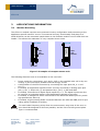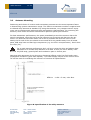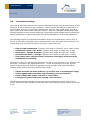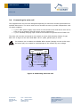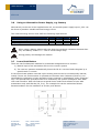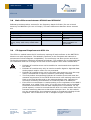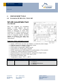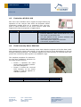
1
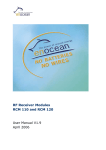
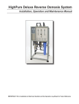
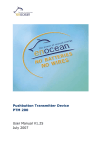
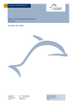
USER MANUAL V1.24 RF Sensor Transmitter Module STM 11x June 24, 2008 Patent protected: WO98/36395 DE 100 25 561 DE 101 50 128 WO 2004/051591 DE 103 01 678 A1 EnOcean GmbH Kolpingring 18a 82041 Oberhaching Germany Phone +49.89.67 34 689-0 Fax +49.89.67 34 689-50 [email protected] www.enocean.com Subject to modifications STM 11x User Manual V1.24 June 24, 2008 10:12 AM Page 1/41 USER MANUAL V1.24 STM 11X REVISION HISTORY The following major modifications and improvements have been made to the first version of this document: No 1.1 1.2 1.21 1.22 1.23 1.24 Major Changes ESD warning added; equivalent schematic of CW_0 and CW_1 corrected. Editorial changes; FCC approval requirements modified Figures in 2.6 corrected V_SC2 instead of V_SC1! Patent information added Variant STM11xC moved to separate User Manual Main differences between STM110 and STM110C added Published by EnOcean GmbH, Kolpingring 18a, 82041 Oberhaching, Germany www.enocean.com, [email protected], phone ++49 (89) 6734 6890 © EnOcean GmbH All Rights Reserved Important! This information describes the type of component and shall not be considered as assured characteristics. No responsibility is assumed for possible omissions or inaccuracies. Circuitry and specifications are subject to change without notice. For the latest product specifications, refer to the EnOcean website: http://www.enocean.com. As far as patents or other rights of third parties are concerned, liability is only assumed for modules, not for the described applications, processes and circuits. EnOcean does not assume responsibility for use of modules described and limits its liability to the replacement of modules determined to be defective due to workmanship. Devices or systems containing RF components must meet the essential requirements of the local legal authorities. The modules must not be used in any relation with equipment that supports, directly or indirectly, human health or life or with applications that can result in danger for people, animals or real value. Components of the modules are considered and should be disposed of as hazardous waste. Local government regulations are to be observed. Packing: Please use the recycling operators known to you. By agreement we will take packing material back if it is sorted. You must bear the costs of transport. For packing material that is returned to us unsorted or that we are not obliged to accept, we shall have to invoice you for any costs incurred. EnOcean GmbH Kolpingring 18a 82041 Oberhaching Germany Phone +49.89.67 34 689-0 Fax +49.89.67 34 689-50 [email protected] www.enocean.com Subject to modifications STM 11x User Manual V1.24 June 24, 2008 10:12 AM Page 2/41 USER MANUAL V1.24 STM 11X TABLE OF CONTENT 1 GENERAL DESCRIPTION...................................................................................... 5 1.1 Basic Functionality......................................................................................... 5 1.2 Typical Applications ....................................................................................... 5 1.3 Technical Data .............................................................................................. 6 1.4 Physical Dimensions ...................................................................................... 7 1.5 Environmental Conditions ............................................................................... 7 1.6 Ordering Information ..................................................................................... 7 2 FUNCTIONAL DESCRIPTION................................................................................. 8 2.1 Block Diagram .............................................................................................. 8 Module power supply ........................................................................................... 8 Power control ..................................................................................................... 9 Power supply outputs .......................................................................................... 9 Wake-up timer.................................................................................................... 9 Processor ..........................................................................................................10 RF transmitter ...................................................................................................10 2.2 Pin Description and operational characteristics..................................................10 2.3 Absolute maximum ratings ............................................................................12 2.4 Equivalent schematics of Inputs and Outputs ...................................................13 Equivalent schematic of WAKE and /WAKE inputs ...................................................13 Equivalent schematic of wake-up cycle time inputs CW_0 to CW_1............................13 Equivalent schematic of LED output ......................................................................14 Equivalent schematic of V_SC1 input ....................................................................14 Equivalent schematic of V_SC2 input ....................................................................15 Equivalent schematic of analog inputs AD_0 to AD_2 ..............................................15 Equivalent schematic of voltage outputs V_0UT and V_REF ......................................15 2.5 Encoding Scheme of CW and CP Input Pins ......................................................16 Wake-up cycle time ............................................................................................16 Presence signal time...........................................................................................16 2.6 Solar Energy Balance Calculation ....................................................................17 2.7 Radio Telegram of STM 11x ...........................................................................19 Frequency range and modulation scheme ..............................................................19 Transmission timing ...........................................................................................19 2.7 Serial Interface for module configuration .........................................................20 Serial protocol ...................................................................................................21 Command list ....................................................................................................22 2.8 Serial Data Reception via Receiver Module RCM 120 ..........................................26 3 APPLICATIONS INFORMATION ............................................................................27 3.1 Module Mounting ..........................................................................................27 3.2 Antenna Mounting ........................................................................................28 3.3 Transmission Range......................................................................................29 3.4 Connecting the solar cell ...............................................................................30 3.5 Solar Cell Handling, Soldering & Mounting........................................................31 Handling ...........................................................................................................31 Soldering ..........................................................................................................31 Gluing ..............................................................................................................33 Corrosion protection ...........................................................................................34 Shade ..............................................................................................................34 EnOcean GmbH Kolpingring 18a 82041 Oberhaching Germany Phone +49.89.67 34 689-0 Fax +49.89.67 34 689-50 [email protected] www.enocean.com Subject to modifications STM 11x User Manual V1.24 June 24, 2008 10:12 AM Page 3/41 USER MANUAL V1.24 STM 11X 3.6 3.7 3.8 3.9 Using an Alternative Power Supply, e.g. Battery ...............................................35 Learn Push Button ........................................................................................35 Main differences between STM110 and STM110C ..............................................36 CE Approval Requirements STM 11x................................................................36 4 DEVELOPMENT TOOLS .......................................................................................37 4.1 Evaluation Kit EVA 120 / EVA 120C .................................................................37 4.2 Evaluation Kit EVA 100..................................................................................38 4.3 Field Intensity Meter EPM 100 ........................................................................38 5 SPECIFICATION OF SS3513 SOLAR CELL ..............................................................39 6 DECLARATION OF CE CONFORMITY .....................................................................41 EnOcean GmbH Kolpingring 18a 82041 Oberhaching Germany Phone +49.89.67 34 689-0 Fax +49.89.67 34 689-50 [email protected] www.enocean.com Subject to modifications STM 11x User Manual V1.24 June 24, 2008 10:12 AM Page 4/41 USER MANUAL V1.24 STM 11X 1 GENERAL DESCRIPTION The extremely power-saving RF transmitter module STM 11x from EnOcean enables the implementation of wireless and maintenance-free sensors. Power supply is provided by a solar cell. An integrated energy store allows operation for several days in total darkness. 1.1 Basic Functionality Three 8-bit A/D converter inputs and 4 digital inputs facilitate multifunctional detector systems, based on passive sensing components. This allows easy and convenient monitoring of temperature, illumination, etc. – or controlling window and door states – or supervising input voltages or input currents respectively. Figure 1: STM 11x sensor transmitter module 1.2 Typical Applications • Building installation • Industrial automation • Consumer electronics The STM 11x module serves the 868 MHz air interface protocol of EnOcean. Together with the receiver module RCM120, RCM130, or the transceiver module TCM120 this module can be easily integrated into operation and control units for the realization of various application-specific system solutions. The module is part of a powerful RF system solution from EnOcean for operation and control applications. Because the RF transmitters are self-powered, maintenance-free RF systems can be implemented. EnOcean GmbH Kolpingring 18a 82041 Oberhaching Germany Phone +49.89.67 34 689-0 Fax +49.89.67 34 689-50 [email protected] www.enocean.com Subject to modifications STM 11x User Manual V1.24 June 24, 2008 10:12 AM Page 5/41 USER MANUAL V1.24 STM 11X 1.3 Technical Data Power supply Solar Power Generator (discrete optical cell), or 2.2 - 5.0V external Frequency / transmission power 868.3 MHz / 10 mW max. Data rate / Modulation type 125 kbps / ASK Transmission range 300m free field, typ. 30m indoor Module identifier individual 32-bit ID factory-programmed EnOcean telegram type 4BS (“Four Byte Sensor”) Telegram packet length (sub-telegram) No. of (redundant) packets 1.2 ms ±5% 3 packets within about 40ms, delay effected at random Input channels 3 x analog inputs (8-bit resolution), 4 x digital inputs Spontaneous wake-up differential external trigger signal, minimum wake interval 7ms Cyclic wake-up user-configurable (every 1, 10, 100, or 110 s, tolerance ± 20%) user-configurable (every wake-up signal, every 10th or every 100th) Presence signal Illumination 100 lx up to 100.000 lx Operation startup time with empty energy store < 10 min @ 400 lx Operation time during total darkness > 60 h 1) 1) storage is filled @ 1000 lx (4.2V in Goldcap) RF transmission every 17 min, 100s wake-up, temperature 25°C, Goldcap formatted Ext. power supply output 3.0 V ±3%, 1mA max., ~2.6ms (during wake-up time) Ext. voltage reference output 2.05V ±3%, 1mA max., ~2.6ms (during wake-up time) Input sample time after wake-up Transmitting indication output (LED) >1.7 ms 3.0V ±3%, 2mA max., 3 x 1.2 ms within 40ms A change of WAKE pin status forces the onboard controller instantly to check all current analog and digital input values. In addition, a user-programmable cyclic wake-up is provided. After wake-up, a radio telegram (input data, unique 32-bit sensor ID, checksum) is transmitted in case of a change of any digital input value compared to the last sending or in case of a significant change of measured analog values: >5LSB of AD_1 input, >6LSB of AD_0 or >14LSB of AD_2. In case of a triggered wake-up a radio telegram is sent in any case. In case of no relevant input change, a presence signal is sent after a user-configurable number of wake-ups to announce all current input values (sign of life). Between the wake-up phases, the module is in sleep mode for minimum power consumption. There is a serial interface which allows configuring several parameters of the module: - Threshold values of the AD inputs which lead to immediate radio transmission - Manufacturer code (information about manufacturer and type of device) In case a manufacturer code is programmed into the module and DI3=0 at wake-up the module will transmit a dedicated teach-in telegram containing the manufacturer code. Observe Precautions, electrostatic sensitive devices! EnOcean GmbH Kolpingring 18a 82041 Oberhaching Germany Phone +49.89.67 34 689-0 Fax +49.89.67 34 689-50 [email protected] www.enocean.com Subject to modifications STM 11x User Manual V1.24 June 24, 2008 10:12 AM Page 6/41 USER MANUAL V1.24 STM 11X 1.4 Physical Dimensions Dimensions of PCB 21.0 x 40.0 x 9.0 mm (incl. energy store and wiring pins) Dimensions of solar cell 35.0 x 13.0 x 1.1 mm (for details see chapter 5) Antenna pre-installed 9 cm whip antenna Connector: 20 pins, dual row male, grid 1.27 mm 20 2 19 1 ANT Figure 2: STM 11x package outlines 1.5 Environmental Conditions Operating temperature -25°C up to +65 °C Storage temperature -25°C up to +65 °C Humidity (PCB) 0% to 95% r.h. Humidity (Solar cell, rear side) 0% to 60% r.h., no condensate 1) 1) For corrosion protection, see chapter 3.5 The product life strongly depends on the temperature as the Goldcap used for energy storage degrades with higher temperature. As a reference the lifetime (capacitance reduced to 70% of nominal value) of the Goldcap is reduced from 100.000 h to 5.000 h when the temperature is raised from 25°C to 65°C. 1.6 Ordering Information Type STM 110 STM 110 EnOcean GmbH Kolpingring 18a 82041 Oberhaching Germany EnOcean Ordering Code S3001-D110 S3001-D111 Phone +49.89.67 34 689-0 Fax +49.89.67 34 689-50 [email protected] www.enocean.com Radio Frequency 868.3 MHz 868.3 MHz Solar Cell Included Not included Subject to modifications STM 11x User Manual V1.24 June 24, 2008 10:12 AM Page 7/41 USER MANUAL V1.24 STM 11X 2 FUNCTIONAL DESCRIPTION 2.1 Block Diagram V_SC1 V_SC2 *) DI_x and AD_x input values are transmitted ... - If wake-up and an input value has changed - At wake-up and presence signal time ANT (whip) RF Transmitter Goldcap LED Power, Data*) Power control & wake-up timer WAKE WAKE CW_1 CW_0 Spontaneous wake-up Wake-up (power on) Processor Digital Inputs Ready (power off) Cyclic wake-up Presence Signal (every 1,10, 100, or 110s) (every 100th, every 10th, every cyclic wake-up) Active during wake-up only V_OUT V_REF GND CP_0 A/D 8-bit DI_0 DI_1 DI_2 DI_3 AD_0 AD_1 AD_2 CP_1 Figure 3: STM 11x block diagram Module power supply The supplied solar cell has been designed especially for the STM 11x for maximum module performance at smallest dimensions. The active solar area is divided into two to provide independent module power supplies: V_SC1: Main power supply input. Must be connected to the STM 11x solar cell (small active area) or by another external energy source respectively V_SC2: Goldcap charging input by connecting to the STM 11x solar cell (big active area) The capacitance of the Goldcap may be reduced after long term storage of modules without energy supply. It may take up to one day of charging until the full capacitance is recovered. Continuous operation at temperatures higher than 50°C may decrease the capacitance of the Goldcap. This will result in shorter charging times and shorter operating times in total darkness! EnOcean GmbH Kolpingring 18a 82041 Oberhaching Germany Phone +49.89.67 34 689-0 Fax +49.89.67 34 689-50 [email protected] www.enocean.com Subject to modifications STM 11x User Manual V1.24 June 24, 2008 10:12 AM Page 8/41 USER MANUAL V1.24 STM 11X Power control The power control supervises V_SC1 supply and charging status of the energy store. It controls the power supply for wake-up timer, microprocessor, HF transmitter and the supply outputs. Power supply outputs Two power supply outputs are available: a) V_OUT b) V_REF (stabilized reference voltage) The outputs are active after wake-up during the active state of the module to drive an external sensor user circuitry. Wake-up timer The wake-up timer provides user-programmable wake-up time intervals for activating the processor and an external wake-up opportunity (WAKE pins). Features: Extremely low power consumption during sleeping time period Cyclic processor wake-up configurable by user through external pin configuration (CW_0, CW_1) The sleep mode can be terminated immediately by changing the pin status of the differential WAKE inputs. Note that the WAKE inputs are part of a special capacitor circuitry that offers lowest operating power consumption (current flow at switching over time only). WAKE and /WAKE always have to be operated via switch-over as shown in the following: WAKE WAKE GND Figure 4: External WAKE pin circuit A radio telegram is always transmitted after wake-up via WAKE pins! (change compared to STM100!) After transmission the presence signal counter is reset. See chapter 2.5 for configuration of wake-up cycle times. EnOcean GmbH Kolpingring 18a 82041 Oberhaching Germany Phone +49.89.67 34 689-0 Fax +49.89.67 34 689-50 [email protected] www.enocean.com Subject to modifications STM 11x User Manual V1.24 June 24, 2008 10:12 AM Page 9/41 USER MANUAL V1.24 STM 11X Processor Controls all functionalities after wake-up: First, the values of all measurement inputs are sampled. After that, a RF signal transmission is triggered if one or more of the following conditions are met: a) One of the input values has changed since the last radio transmission (one of the 4 digital inputs has changed or one of the 3 analog inputs has changed equal to or more than a defined value of the total measurement range), or b) Presence Signal time, that means number of wake-ups that did not cause a radio transmission has been counted to a user-configurable number (CP_0 and CP_1), or c) The wake-up has been triggered via the WAKE pins After every RF transmission, all measurement values are stored for data comparison at next wake-up time. See chapter 2.5 for configuration of presence signal timing. RF transmitter The radio transmitter is powered up by the processor when the sending condition is positive. The output LED is activated temporarily during telegram transmission. 2.2 Pin 5 6 7 Pin Description and operational characteristics Symbol AD_0 AD_1 AD_2 Function Analog inputs sampled at every wake-up. The analog input values are transmitted as sensor data bytes: AD_0 = DATA_BYTE1 AD_1 = DATA_BYTE2 AD_2 = DATA_BYTE3 2 1 4 3 DI_0 DI_1 DI_2 DI_3 EnOcean GmbH Kolpingring 18a 82041 Oberhaching Germany Digital inputs sampled at every wake-up. Digital inputs are transmitted within sensor DATA_BYTE0 (least significant 4 bits): DI_0 = Bit 0, DI_1 = Bit 1, DI_2 = Bit Phone +49.89.67 34 689-0 Fax +49.89.67 34 689-50 [email protected] www.enocean.com Operational Characteristics Sample moment after wake-up: 2.6 ms Resolution: 8-bit Input impedance: >100kΩ 1.7 ms … (1 bit = V_REF/256 = 8mV Accuracy vs. V_REF @25°C typ. ±2LSB, max ±4LSB). Relevant input change: > 5 LSB of AD_1 > 6 LSB of AD_0 > 14 LSB of AD_2 These default values may be changed. See page 22 Sample moment after wake-up: 1.7 ms … 2.6 ms Real digital TTL input with internal pull-up (change compared to STM100!) LOW voltage: <0.45 V HIGH voltage: > 2.45V Input impedance >100kΩ Subject to modifications STM 11x User Manual V1.24 June 24, 2008 10:12 AM Page 10/41 USER MANUAL V1.24 STM 11X 2, DI_3 = Bit3). DI_2 and DI_3 are also used as serial interface pins for the configuration of the module. See page 20. A signal change of WAKE inputs stops sleep mode immediately. A radio telegram is always transmitted after wake-up via WAKE pins! (change compared to STM100!) 18 20 WAKE /WAKE 12 14 CW_0 CW_1 Encoding input for processor wake-up cycle time: 1, 10, 100, or 110 seconds approximately. 13 15 CP_0 CP_1 9 V_OUT 10 V_REF 11 LED Encoding input for determining the number of cyclic wake-up signals that trigger the Presence Signal: Every wake-up signal, or every 10th, or every 100th or no presence signal. Module power supply output available during wake-up phase to drive an external sensor circuitry by the user. Also used for starting serial mode. Reference voltage output available during wake-up phase to drive an external sensor circuit by the user. Output for optional external LED to indicate every telegram transmission (short flashing) 19 V_SC1 17 V_SC2 EnOcean GmbH Kolpingring 18a 82041 Oberhaching Germany Also used for starting serial mode. Main power supply input. Connect V_SC1 in series with a Schottky diode of Type BAS 125 to SOL1 of the STM 11x solar cell (smaller area, see Figure 9). Or connect to another external energy source respectively. Goldcap charging input. Connect V_SC2 in series with a Schottky Phone +49.89.67 34 689-0 Fax +49.89.67 34 689-50 [email protected] www.enocean.com Differential input (capacitive): - connect to GND via switch over only - Resistance to GND < 100 Ω - Switch over time < 1ms - Minimum time between wake signals > 7ms - Pins should be connected to V_SC1 if not needed in application - max. external allowed leakage current 100pA Pins should be left open or connected to GND Resistance to GND < 10 Ω Cyclic wake-up time value strongly depends on actual power supply voltage and temperature (up to ±20%) Pins should be left open or connected to GND Resistance to GND < 100 Ω Input impedance >100kΩ 3.0V ±3%, ~2.6ms, IVout = 1 mA max. 2.05 V ±3%, ~2.6ms, IVref = 1 mA max. 3.0 V ±3%, 2 mA max., source impedance 470 Ω ±1%, ~3 x 1.2 ms within 40 ms When using other energy source than the supplied solar panel (see chapter 3.6): 2.2 – 5.0 V For use with the solar cell only (Vo < 5.0 V)! Subject to modifications STM 11x User Manual V1.24 June 24, 2008 10:12 AM Page 11/41 USER MANUAL V1.24 STM 11X diode of Type BAS 125 to SOL2 of the STM 11x solar cell (bigger area, see Figure 9). 8 16 GND Ground connections ANT Whip antenna λ/4 Please find recommendations on antenna mounting in chapter 3.2 Never connect an input (like CP_0..1, AD_0..2, DI_0..3) to a permanent supply voltage! These inputs should be always left open, connected to GND or connected to the own V_OUT and / or V_REF (active only during measurement time!). Otherwise they would permanently draw current from the permanent power supply and could also damage the device (see absolute maximum ratings 2.3 below) If such a function is absolutely needed, please insert a diode to avoid the problem. For socket positions, see Figure 2. 2.3 Absolute maximum ratings Symbol Parameter V_SC1, V_SC2 V_SC1 V_SC2 LED, V_REF, V_OUT, DI0..3, AD0..2, CP_0..1 LED, DI0..3, AD0..2 V_OUT CW_0, CW_1 WAKE, /WAKE ANT V_REF, V_OUT LED V_SC1, V_SC2, CW_0, CW1, WAKE, /WAKE, V_OUT, V_REF, ANT, GND CP_0, CP_1, LED, DI_0..3, AD_0..2 Module Module Solar cell Solar cell Input voltage Input current ripple Input current ripple Input voltage while µC not active (= module completely switched off or sleep timer running) Input voltage while µC active Input voltage while serial mode is active Input voltage Input voltage Input voltage Output current Output current Electrostatic discharge Min Max Units 0 5.5 95 0.2 0.7 V mA A V V_OUT 3.09 0 V_SC1 5 1 2 1 V V V V V mA mA kV 2 kV 65 95 100.000 60 °C % r.h. lx % r.h. 0 0 0 0 Electrostatic discharge Temperature Humidity Illumination Humidity -25 Exceeding these values may destroy the module! EnOcean GmbH Kolpingring 18a 82041 Oberhaching Germany Phone +49.89.67 34 689-0 Fax +49.89.67 34 689-50 [email protected] www.enocean.com Subject to modifications STM 11x User Manual V1.24 June 24, 2008 10:12 AM Page 12/41 USER MANUAL V1.24 STM 11X 2.4 Equivalent schematics of Inputs and Outputs Equivalent schematic of WAKE and /WAKE inputs WAKE ______ WAKE Equivalent schematic of wake-up cycle time inputs CW_0 to CW_1 CW_0 83n 5nA CW_1 1µ 6.8n EnOcean GmbH Kolpingring 18a 82041 Oberhaching Germany Phone +49.89.67 34 689-0 Fax +49.89.67 34 689-50 [email protected] www.enocean.com Threshold detector 1M Subject to modifications STM 11x User Manual V1.24 June 24, 2008 10:12 AM Page 13/41 USER MANUAL V1.24 STM 11X Equivalent schematic of LED output Equivalent schematic of V_SC1 input R_C1 R_STM V_SC1 C1 470µF R_C1: ~6 MΩ after 3 V applied for 10 min, >>10MΩ after 24h. R_STM: depends on wake-up cycle time, transmit intervals and supply voltage. In the following table R_STM is given at a supply voltage of 3V (typical values): R_STM [kΩ] Every wake-up Every 10th wake-up Every 100th wake-up 1s 24 63 75 10s 240 630 750 100s 2400 6300 7500 110s 2600 6900 8300 The current consumption is almost independent from the supply voltage (typical values): I_STM [µA] Every wake-up Every 10th wake-up Every 100th wake-up EnOcean GmbH Kolpingring 18a 82041 Oberhaching Germany Phone +49.89.67 34 689-0 Fax +49.89.67 34 689-50 [email protected] www.enocean.com 1s 130 50 40 10s 13 5.0 4.0 100s 1.3 0.50 0.40 110s 1.1 0.45 0.35 Subject to modifications STM 11x User Manual V1.24 June 24, 2008 10:12 AM Page 14/41 USER MANUAL V1.24 STM 11X Equivalent schematic of V_SC2 input V_SC1 C2 0.1F R_C2 V_SC2 R_C2: ~375 kΩ after 3 V applied for 10 min., ~5MΩ after 24h Equivalent schematic of analog inputs AD_0 to AD_2 Sample Switch AD_x Rs = 10k max 120p 1M Equivalent schematic of voltage outputs V_0UT and V_REF 470 V_OUT Vpulse < 1 mA LMV 358 EnOcean GmbH Kolpingring 18a 82041 Oberhaching Germany Phone +49.89.67 34 689-0 Fax +49.89.67 34 689-50 [email protected] www.enocean.com V_REF Subject to modifications STM 11x User Manual V1.24 June 24, 2008 10:12 AM Page 15/41 USER MANUAL V1.24 STM 11X 2.5 Encoding Scheme of CW and CP Input Pins The encoding input pins have to be left open or connected to GND in correspondence with the following connection schemes: Wake-up cycle time CW_0 CW_1 Wake-up cycle time NC NC 1 sec. ±20% GND NC 10 sec. ±20% NC GND 100 sec. ±20% GND GND 110 sec. ±20% Presence signal time Via CP_0 and CP_1 an internal counter is set which is decreased at every wake-up signal. Once the counter reaches zero the presence signal is transmitted. CP_0 CP_1 NC NC Number of cyclic wake-up signals that trigger the presence signal Every timer wake-up signal GND NC Every 10th timer wake-up signal NC GND Every 100th timer wake-up signal GND GND No presence signal after timer wake-up A radio telegram is always transmitted after wake-up via WAKE pins! (change compared to STM100!) After transmission the presence signal counter is reset. EnOcean GmbH Kolpingring 18a 82041 Oberhaching Germany Phone +49.89.67 34 689-0 Fax +49.89.67 34 689-50 [email protected] www.enocean.com Subject to modifications STM 11x User Manual V1.24 June 24, 2008 10:12 AM Page 16/41 USER MANUAL V1.24 STM 11X 2.6 Solar Energy Balance Calculation The following diagrams are showing operational performance data of STM110. 6 5 Voltage V_SC2[V] 4 3 2 1 0 0 5 10 15 20 25 charging Charging time time [h] [h] Charging at 1000 lx Charging at 200 lx Charging at 50 lx Figure 5: Graphs of the goldcap charging process (typ. @25°C). Measured with white light LEDs, illustration of the illumination level as fluorescent lamp equivalent (EL). Measured with 100s wake up timer. EnOcean GmbH Kolpingring 18a 82041 Oberhaching Germany Phone +49.89.67 34 689-0 Fax +49.89.67 34 689-50 [email protected] www.enocean.com Subject to modifications STM 11x User Manual V1.24 June 24, 2008 10:12 AM Page 17/41 USER MANUAL V1.24 STM 11X 6 Figure 6: STM110 operation time in darkness (typ. @25°C) 5 3 1 sec timer Voltage Voltage V_SC2[V] V_SC2[V] Voltage V_SC1 [V] 4 2 1 0 3 2 1 0 Operating time darkness[h] [h] Operating time in in darkness 6 5 3 10 sec timer Voltage V_SC2[V] Voltage V_SC1 [V] 4 2 1 0 30 25 20 15 10 5 0 Operating time darkness[h] [h] Operating time in in darkness 6 5 3 100 sec timer Voltage V_SC2[V] Voltage V_SC1 [V] 4 2 1 0 150 120 90 60 30 0 Operating time darkness[h] [h] Operating time in in darkness Telegram transmission at every wake up Telegram transmission every 10th wake up Telegram transmission every 100th wake up EnOcean GmbH Kolpingring 18a 82041 Oberhaching Germany Phone +49.89.67 34 689-0 Fax +49.89.67 34 689-50 [email protected] www.enocean.com Subject to modifications STM 11x User Manual V1.24 June 24, 2008 10:12 AM Page 18/41 USER MANUAL V1.24 STM 11X In the figure left typical values are shown. In worst case the operating time in darkness may be 20% less! 2.7 Radio Telegram of STM 11x Frequency range and modulation scheme The STM 11x operates the 868.3 MHz radio channel (868.0 – 868.6 MHz), which is exclusively released for short-time data transmission in Europe. Timing conditions can be found in chapter 3.8 of this paper. STM11x is based on ASK (amplitude shift keying) modulation with a bit rate of 125 kbit/s. Telegram content The payload of the telegram consists of: 8 bit 8 bit 8 bit 4 bit AD_2 AD_1 AD_0 DI_3..0 32 bit ID Transmission timing The transmission timing of the radio module STM 11x has been developed to avoid possible collisions with data packages of other EnOcean transmitters as well as disturbances from the environment. With each transmission cycle, 3 identical sub telegrams are transmitted. The transmission of a sub telegram lasts approximately 1.2 ms. To optimize data security, each telegram is repeated twice within about 40 ms, whereas the delay between the three transmission bursts is effected at random. EnOcean GmbH Kolpingring 18a 82041 Oberhaching Germany Phone +49.89.67 34 689-0 Fax +49.89.67 34 689-50 [email protected] www.enocean.com Subject to modifications STM 11x User Manual V1.24 June 24, 2008 10:12 AM Page 19/41 USER MANUAL V1.24 STM 11X 2.7 Serial Interface for module configuration It is possible to change some parameters of the module via a serial interface: - Read / write threshold values of AD_0 to AD_2 which lead to a transmission of a radio protocol - Read the firmware version of the module - Read / write manufacturer ID, device profile and type The following - pins are needed: LED V_OUT DI_3 as USR_RX DI_2 as USR_TX In order to activate the serial mode please take the following steps: 1. Connect LED pin to V_OUT pin 2. Activate STM11x using the timer or the WAKE inputs. The module will then enter the serial mode. It will receive information via the USR_RX (DI_3) pin and transmit information via the USR_TX (DI_2) pin. It will not react on WAKE signals or timer interrupts while in serial mode. In order to terminate the serial mode the LED pin has to be connected to GND. EnOcean GmbH Kolpingring 18a 82041 Oberhaching Germany Phone +49.89.67 34 689-0 Fax +49.89.67 34 689-50 [email protected] www.enocean.com Subject to modifications STM 11x User Manual V1.24 June 24, 2008 10:12 AM Page 20/41 USER MANUAL V1.24 STM 11X Serial protocol The data rate is 9600 baud, 1 start bit, 1 stop bit, LSB first. The inter byte time out is 50ms. The default logic value is 1(3V). A serial command consists of 14 bytes as shown in the following. SYNC_BYTE1 (A5 Hex) SYNC_BYTE0 (5A Hex) HEADER ORG DATA_BYTE0 DATA_BYTE1 DATA_BYTE2 DATA_BYTE3 DATA_BYTE4 DATA_BYTE5 DATA_BYTE6 DATA_BYTE7 DATA_BYTE8 CHECKSUM SYNC_BYTE1 SYNC_BYTE0 HEADER ORG DATA_BYTE0..8 CHECKSUM EnOcean GmbH Kolpingring 18a 82041 Oberhaching Germany (8 bit) = 0xA5 (fixed) (8 bit) = 0x5A (fixed) (8 bit) = 0x8B telegram sent from STM 0xAB telegram sent to STM (8 bit) = 0 … 255 telegram type (see description of commands) (8 bit) = 0 … 255 information (8 bit) = 0 … 255 checksum (Last 8LSB from addition of all octets except sync bytes and checksum) Phone +49.89.67 34 689-0 Fax +49.89.67 34 689-50 [email protected] www.enocean.com Subject to modifications STM 11x User Manual V1.24 June 24, 2008 10:12 AM Page 21/41 USER MANUAL V1.24 STM 11X Command list WR_SYS_AD_THRES Description: With this command the user can modify the threshold values at the analogue inputs which lead to a radio transmission. The default values are 6LSB on AD_0, 5LSB on AD_1 and 14 LSB on AD_2. The module will answer with OK_SYS_WR or ERR_SYS_WR. Command encoding Bit 7 Bit 0 0xA5 0x5A 0xAB 0x02 AD_2_MIN_VARIATION AD_1_MIN_VARIATION AD_0_MIN_VARIATION 0xXX 0xXX 0xXX 0xXX 0xXX 0xXX ChkSum AD_2_MIN_VARIATION: Threshold at AD_2: 0…0xFF LSB AD_1_MIN_VARIATION: Threshold at AD_1: 0…0xFF LSB AD_0_MIN_VARIATION: Threshold at AD_0: 0…0xFF LSB 0xXX Ignored field A reduction of the threshold values may lead to a higher number of transmissions and therefore increased energy consumption! The measurement accuracy versus V_REF is typ. ±2LSB, max ±4LSB! RD_SYS_MEM Description: With this command the user can retrieve all the configuration data from the module. The module answers with 3 telegrams: • INF_SYS_SW_VERSION • INF_SYS_ID_DEV_MAN • INF_SYS_AD_THRES EnOcean GmbH Kolpingring 18a 82041 Oberhaching Germany Phone +49.89.67 34 689-0 Fax +49.89.67 34 689-50 [email protected] www.enocean.com Subject to modifications STM 11x User Manual V1.24 June 24, 2008 10:12 AM Page 22/41 USER MANUAL V1.24 STM 11X Command encoding Bit 7 Bit 0 0xA5 0x5A 0xAB 0x40 0xXX 0xXX 0xXX 0xXX 0xXX 0xXX 0xXX 0xXX 0xXX ChkSum 0xXX ignored field INF_SYS_ID_DEV_MAN Description: This message contains the manufacturer ID, and the device profile and type. Command encoding Bit 7 Bit 0 0xA5 0x5A 0x8B 0x00 DATA_BYTE3 DATA_BYTE2 DATA_BYTE1 0x00 ID_Byte3 ID_Byte2 ID_Byte1 ID_Byte0 0x00 ChkSum Data_Byte3..0: Data_Byte3 as follows: Data_Byte2 Data_Byte1 7 6 5 4 3 2 1 0 7 6 5 4 3 2 1 0 7 6 5 4 3 2 1 0 Profile ID_Byte3..0: Type Manufacturer ID STM11x ID bytes. In order to prevent fraudulent use, the commands for writing manufacturer ID, device profile and type to the module are only available to customers signing an agreement with EnOcean! EnOcean GmbH Kolpingring 18a 82041 Oberhaching Germany Phone +49.89.67 34 689-0 Fax +49.89.67 34 689-50 [email protected] www.enocean.com Subject to modifications STM 11x User Manual V1.24 June 24, 2008 10:12 AM Page 23/41 USER MANUAL V1.24 STM 11X INF_SYS_SW_VERSION Description: This telegram contains the SW version of the module. Command encoding Bit 7 Bit 0 SW SW SW SW 0xA5 0x5A 0x8B 0x8C Version Version Version Version 0x00 Byte3 Byte2 Byte1 Byte0 0x00 0x00 0x00 0x00 ChkSum SW Version Byte3..0: Software version, MSB first INF_SYS_AD_THRES Description: This telegram contains the current threshold values at the analogue inputs which lead to a radio transmission. Command encoding Bit 7 Bit 0 0xA5 0x5A 0x8B 0x01 AD_2_MIN_VARIATION AD_1_MIN_VARIATION AD_0_MIN_VARIATION 0x00 0x00 0x00 0x00 0x00 0x00 ChkSum AD_2_MIN_VARIATION: Threshold at AD_2: 0…0xFF LSB AD_1_MIN_VARIATION: Threshold at AD_1: 0…0xFF LSB AD_0_MIN_VARIATION: Threshold at AD_0: 0…0xFF LSB EnOcean GmbH Kolpingring 18a 82041 Oberhaching Germany Phone +49.89.67 34 689-0 Fax +49.89.67 34 689-50 [email protected] www.enocean.com Subject to modifications STM 11x User Manual V1.24 June 24, 2008 10:12 AM Page 24/41 USER MANUAL V1.24 STM 11X OK_SYS_WR Description: This message is sent after successful execution of a user request. Command encoding Bit 7 Bit 0 0xA5 0x5A 0x8B 0x58 0x00 0x00 0x00 0x00 0x00 0x00 0x00 0x00 0x00 ChkSum ERR_SYS_WR Description: This message is sent if the execution of a user request has failed. Command encoding Bit 7 Bit 0 0xA5 0x5A 0x8B 0x19 0x00 0x00 0x00 0x00 0x00 0x00 0x00 0x00 0x00 ChkSum EnOcean GmbH Kolpingring 18a 82041 Oberhaching Germany Phone +49.89.67 34 689-0 Fax +49.89.67 34 689-50 [email protected] www.enocean.com Subject to modifications STM 11x User Manual V1.24 June 24, 2008 10:12 AM Page 25/41 USER MANUAL V1.24 STM 11X 2.8 Serial Data Reception via Receiver Module RCM 120 For a detailed description please refer to the User Manual of RCM 120. Type of STM 11x protocol which is seen at the serial outputs of the receiver modules is “4BS” (4 Byte Sensor): Description of STM 11x radio data content: ORG = 7 dec. always (EnOcean module type “4BS”) DATA_BYTE3 = DATA_BYTE2 = DATA_BYTE1 = DATA_BYTE0 = Bit 7 Reserved Value of AD_2 analog input Value of AD_1 analog input Value of AD_0 analog input Digital sensor inputs as follows: Bit 0 DI_3 DI_2 DI_1 DI_0 ID_BYTE3 ID_BYTE2 ID_BYTE1 ID_BYTE0 module module module module = = = = identifier identifier identifier identifier (Byte3) (Byte2) (Byte1) (Byte0) In case manufacturer ID, device profile and type have been stored in the module the following telegram will be seen on the RCM 120 serial interface if DI_3=0: Description of STM 11x learn telegram: ORG = 7 dec. always (EnOcean module type “4BS”) DATA_BYTE0..3 see below LRN Type = 1 LRN = 0 DI0..DI2: current status of digital inputs Profile, Type, Manufacturer-ID defined by manufacturer ID_BYTE3 = module identifier (Byte3) ID_BYTE2 = module identifier (Byte2) ID_BYTE1 = module identifier (Byte1) ID_BYTE0 = module identifier (Byte0) ORG Data_Byte3 Profile Type 6 Bit 7 Bit Data_Byte2 Manufacturer-ID 11 Bit Data_Byte1 Data_Byte0 ID LRN Type RE2 RE1 RE0 LRN DI2 DI1 DI0 1Bit 1Bit 1Bit 1Bit 1Bit 1Bit 1Bit 1Bit With this special learn telegram it is possible to identify the manufacturer of a device and the profile and type of a device. There is a list available describing the functionalities of the respective products. Please contact EnOcean to receive this list. EnOcean GmbH Kolpingring 18a 82041 Oberhaching Germany Phone +49.89.67 34 689-0 Fax +49.89.67 34 689-50 [email protected] www.enocean.com Subject to modifications STM 11x User Manual V1.24 June 24, 2008 10:12 AM Page 26/41 USER MANUAL V1.24 STM 11X 3 APPLICATIONS INFORMATION 3.1 Module Mounting User PCB User PCB Space required Energy stores The STM 11x module requires some external circuitry configuration and connecting to the application-specific sensoric circuit. This external circuitry should easily find place on a small PCB that can be connected upside down to the EnOcean module via the STM dual row header. This allows the realization of very compact sensor units. STM 110 Module 9 mm STM 110 Module 9 mm Figure 7: Examples of compact sensor unit The following features have to be available on the user PCB: Power supply by connecting V_SC1 and V_SC2 to the supplied solar cell or by connecting V_SC1 to another suitable external energy source Configuration of the STM firmware by connecting the input pins CW_0..1 and CP_0..1 If needed, an application-specific sensor circuitry connected to analog input pins (AD_0, AD_1, and/or AD_2) and powered by V_OUT, V_REF and GND If needed, connections to digital signal inputs DI_0..3. The digital inputs can also be used for an individual sensor type identification defined by the user. If needed, a changeover switch connected to the differential WAKE pins for providing spontaneous wake-up If needed, a light emitting diode connected between the LED and GND pins for providing optical feedback of sending To avoid radio frequency pickup from the environment, strip lines of the user circuit should be designed as short as possible, and the use of a PCB ground plane layer is recommended. EnOcean GmbH Kolpingring 18a 82041 Oberhaching Germany Phone +49.89.67 34 689-0 Fax +49.89.67 34 689-50 [email protected] www.enocean.com Subject to modifications STM 11x User Manual V1.24 June 24, 2008 10:12 AM Page 27/41 USER MANUAL V1.24 STM 11X 3.2 Antenna Mounting Positioning and choice of receiver and transmitter antennas are the most important factor in determining system transmission range. The STM11x transmitter module is supplied with a soldered whip antenna as standard. By using that antenna, very compact sensor equipment can be implemented with good radio transmission characteristics. For mounting the antenna, some notes should be considered to optimize system performance: For best transmitter performance, the space immediately around the antenna has to be strictly considered, since this has a strong influence on screening and detuning the antenna. The antenna should be drawn out as far as possible and must be never cut off. Mainly the far end of the wire should be mounted as far as possible away from all metal parts, PCB strip lines and fast logic components (e.g. the STM microprocessor). Don’t short the whip (λ/4). For a good antenna performance don’t roll up or twist the whip and please draw attention to an overall whip distance of at least 10 mm (20 mm is better) from any PCB strip, ground plane and conductive part or electric part. Note that whip antennas do not show any directional effects under free-field radio-wave propagation conditions (spot-wise radiator). The RSSI voltage output of the receiver module can be used for evaluating the influence of intuitive RF optimizations. STM11x : L=89 ± 2 mm, color blue Figure 8: Specification of the whip antenna EnOcean GmbH Kolpingring 18a 82041 Oberhaching Germany Phone +49.89.67 34 689-0 Fax +49.89.67 34 689-50 [email protected] www.enocean.com Subject to modifications STM 11x User Manual V1.24 June 24, 2008 10:12 AM Page 28/41 USER MANUAL V1.24 STM 11X 3.3 Transmission Range The main factors that influence the system transmission range are type and location of the antennas of the receiver and the transmitter, type of terrain and degree of obstruction of the link path, sources of interference affecting the receiver, and “dead” spots caused by signal reflections from nearby conductive objects. Since the expected transmission range strongly depends on this system conditions, range tests should categorically be performed before notification of a particular range that will be attainable by a particular application. The following figures for expected transmission range are considered by using a PTM, a STM or a TCM radio transmitter device and the RCM or the TCM radio receiver device with preinstalled whip antenna and may be used as a rough guide only: Line-of-sight connections: Typically 30m range in corridors, up to 100m in halls Plasterboard walls / dry wood: Typically 30m range, through max. 5 walls Brick walls / aerated concrete: Typically 20m range, through max. 3 walls Ferroconcrete walls / ceilings: Typically 10m range, through max. 1 ceiling Fire-safety walls, elevator shafts, staircases and supply areas should be considered as screening. The angle at which the transmitted signal hits the wall is very important. The effective wall thickness – and with it the signal attenuation – varies according to this angle. Signals should be transmitted as directly as possible through the wall. Wall niches should be avoided. Other factors restricting transmission range: Switch mounted on metal surfaces (up to 30% loss of transmission range) Hollow lightweight walls filled with insulating wool on metal foil False ceilings with panels of metal or carbon fiber Lead glass or glass with metal coating, steel furniture The distance between EnOcean receivers and other transmitting devices such as computers, audio and video equipment that also emit high-frequency signals should be at least 0.5m. EnOcean GmbH Kolpingring 18a 82041 Oberhaching Germany Phone +49.89.67 34 689-0 Fax +49.89.67 34 689-50 [email protected] www.enocean.com Subject to modifications STM 11x User Manual V1.24 June 24, 2008 10:12 AM Page 29/41 USER MANUAL V1.24 STM 11X 3.4 Connecting the solar cell The supplied solar cell has been designed especially for maximum module performance at smallest dimensions. The active solar area is divided into two to provide independent module power supplies: V_SC1: Main power supply input. Must be connected to the small active area of the solar cell or to another external energy source respectively V_SC2: Goldcap charging input. Must be connected to big active area of solar cell The solar cell must be connected to the module in series with Schottky Diodes of type BAS 125. In Figure 9 the dual diode BAS 125-07 (SMD, parallel pair) is used. For outdoor use in addition the BZX84-B5V1 diodes (leakage current at 2V must be below 2µA) are needed to avoid damage of the module by over voltage. SOLAR CELL 30% SOL1 GND 70% SOL2 2x BZX84-B5V1 for outdoor applications BAS 125-07W V_SC1 V_SC2 Figure 9: Connecting the solar cell EnOcean GmbH Kolpingring 18a 82041 Oberhaching Germany Phone +49.89.67 34 689-0 Fax +49.89.67 34 689-50 [email protected] www.enocean.com Subject to modifications STM 11x User Manual V1.24 June 24, 2008 10:12 AM Page 30/41 USER MANUAL V1.24 STM 11X 3.5 Solar Cell Handling, Soldering & Mounting The EnOcean solar cell technology guarantees the highest stabilized efficiency values. At the front, the solar modules have a glass covering that protects the photovoltaic layer from the effects of the environment and weather. The rear features contacts for the electrical connection. Handling Prevent injuries due to the sharp glass edges. Always handle the modules carefully, avoid damage of the glass edges that leads to glass breakage or glass chips. The layers are sensitive to punctual pressure, scratching or grinding. During handling and processing, always make sure that no particles are pushed into the coating. Scratches, imprints or particles pushed into the layer can lead to short-circuiting of the module, thus deterioration. The processing of the modules with lacquer spray processes or edge grinding could lead to an impairment of the electrical function of the module (electrostatic influences). In case of necessary module cleaning, the following cleaning agents are suggested: Kleenex (200 tissues, Code 7107, D 0261 8930, Kimberly-Clark) / highpure DI- water / Ethanol (min. 99,8 Vol.%). Soldering The solar panel has 3 connection pads on the rear side. On one side you will see the minus sign. This is the GND connection. Apparatus Soldering iron: Temperature-controlled type with 60W heater at least and +/- 5°C control range is recommended. Soldering iron tip: Slant type or point type. Temperature Measuring Device: A calibrated contact-type temperature meter (e.g. Anritsu Model No. HL-100). Materials Pb-free solder wire: Sn96.5/Ag3.0/Cu0.5, ∅ 0.8 mm, (e.g. Kester 245) Lead wire: Dependent on the type of solar cell, use 20 - 30 AWG multi-threads stranded type. For Pb-free soldering, the lead wire component shall be complied with RoHS requirement. Procedure for hand soldering Environment: Soldering operation shall be performed in a clean environment with ventilation to remove soldering fume during the operation. Soldering temperature calibration o Temperature measuring device: The device (e.g. Anritsu Model No. HL-100) shall be stabilized at room temperature prior to and during calibration. o Timing: Calibrate the soldering iron tip before the operation or every 30 minutes after the soldering. o Procedure EnOcean GmbH Kolpingring 18a 82041 Oberhaching Germany Phone +49.89.67 34 689-0 Fax +49.89.67 34 689-50 [email protected] www.enocean.com Subject to modifications STM 11x User Manual V1.24 June 24, 2008 10:12 AM Page 31/41 USER MANUAL V1.24 STM 11X (a) In Pb alloy soldering, the soldering iron shall be set up and stabilized at 240°C before and in the calibration. For Pb-free solder wire, the soldering iron shall be set up and stabilized at 255°C before and in the calibration. (b) Take little solder wire on the soldering iron tip and put the tip in contact with the contact-pad of the temperature meter for 1 minute. (c) Temperature shown on the temperature meter shall be 255°C (Pbfree) at least for one minute otherwise re-adjust the temperature setting of the soldering iron. Soldering operation Step 1: Make soldering iron tip and solder wire contact with the copper paste of solar cell together. At this moment, tin pot formed in a shape of half ball type or makes a plane type on the copper paste. All the processes shall be well done less than 2 seconds. Step 2: Melt solder wire on the top of solder lead wire. Weld the tin pot again and put the lead wire into the inside of tin pot. Take off the solder iron tip. Finish this step within 2 second also. Soldering operation on the solar cell shall be non-destructive. At any time, only make the soldering iron tip contact the copper paste of the solar cell less than 2 seconds. Attention o Hold the soldering iron at an angle of 30° to 45° with the solar cell in the welding process o Lead wire is in the contact with the copper paste at an angle of 15° o Make sure the welding process not more than the time limit and the lead wire in good contact with copper paste through the solder. Please watch out the loose contact between the lead wire and the copper paste if any o Do not move the lead wires and solar cell before cooling the tin pots o Weld soldering is always with smooth surface and with shine. Test criteria o Pull strength in vertical direction: more than 500 gram o Pull strength in horizontal direction: more than 200 gram Note 1: For pull strength test, the lead wire used should be 28-30 AWG multithreads stranded type Note 2: Lead wire breakage is excluded EnOcean GmbH Kolpingring 18a 82041 Oberhaching Germany Phone +49.89.67 34 689-0 Fax +49.89.67 34 689-50 [email protected] www.enocean.com Subject to modifications STM 11x User Manual V1.24 June 24, 2008 10:12 AM Page 32/41 USER MANUAL V1.24 STM 11X Operation illustration Step 1 Step 2 Some solder Step 3 Solder Step 4 30°-45° Lead Solder SOLAR CELL Lead wire Soldering iron Less than 2 sec Temperature meter Some solder SOLAR CELL 15° Less than 2 sec The function of the solar module may be impaired by exceeding the recommended soldering temperature and the specified soldering time! Gluing XE16-508 Loctite 403 Figure 10: Gluing the solar cell Instead of soldering it is also possible to glue the solar cell onto a PCB. It is proposed to use the following adhesives: a) GE Bayer Silicones XE16-508 (electroconductive adhesive) b) Loctite 403 (to increase mechanical stability) First the XE16-508 is put onto the contact pads of the solar cell. Then a drop of Loctite 403 is put in the middle of the solar cell. After that the solar cell is put onto the PCB. Then the solar cell is pressed onto the PCB accompanied by small rotary movements (<<1mm). Wear gloves to avoid finger prints on solar cell! The curing time of Loctite 403 is only 5 seconds once the solar cell is pressed onto the PCB. Positioning must be finished by then! EnOcean GmbH Kolpingring 18a 82041 Oberhaching Germany Phone +49.89.67 34 689-0 Fax +49.89.67 34 689-50 [email protected] www.enocean.com Subject to modifications STM 11x User Manual V1.24 June 24, 2008 10:12 AM Page 33/41 USER MANUAL V1.24 STM 11X Corrosion protection Corrosion protection is essential to the lifetime of the solar module. The solar module is extremely resistant to temperature effects. But mounting must particularly provide protection against humidity. The proper choice of suitable sealing material is important. The best method is protection by a transparent cover, mainly important for outdoor applications. Also well-suited is a casing by silicone (not acrylic!). With every kind of protection solution, it is very important that the cell edges and the metallic contact areas are covered. Figure 11: Examples of solar cell mounting Shade During installation, care should be taken to ensure that the active photovoltaic area is not shaded. The cells (strips), which produce the least current due to shade, determine the total module current. EnOcean GmbH Kolpingring 18a 82041 Oberhaching Germany Phone +49.89.67 34 689-0 Fax +49.89.67 34 689-50 [email protected] www.enocean.com Subject to modifications STM 11x User Manual V1.24 June 24, 2008 10:12 AM Page 34/41 USER MANUAL V1.24 STM 11X 3.6 Using an Alternative Power Supply, e.g. Battery Alternatively to the use of the supplied solar cell, the module power supply input V_SC1 can be driven by another suitable external energy source. The external energy source must fulfill the following requirements: Parameter Open circuit voltage Ampacity (Peak) Ampacity (continuous) Min 2.2 10 1 Typ Max 5.0 Unit V mA µA When using a battery please take care that the transistion resistance between battery and battery holder is << 10Ω to avoid voltage drop! Wrong polarity will damage the module! 3.7 Learn Push Button There are two fundamental methods for transmitter assignments to a receiver: 1.) Manual input of the transmitter ID into the receiver system 2.) The receiver systems automatically learns the ID of a received radio telegram by a special teach-in routine In the second case please note that cyclic sending sensors can be unintentionally learned, mainly if there are some sensors in operation at the same time. Because of that it is recommended to implement a learn procedure that is reacting to a dedicated “Learn Telegram” only. This special learn procedure has to be realized by the system intelligence after RCM 120 serial interface. RCM 130 features a special learn mode which allows to learn 4BS transmitters only with LRN bit (DI_3=0). For example this can be realized as follows. Recommendation for the realization of a learn push button: EnOcean GmbH Kolpingring 18a 82041 Oberhaching Germany Phone +49.89.67 34 689-0 Fax +49.89.67 34 689-50 [email protected] www.enocean.com Subject to modifications STM 11x User Manual V1.24 June 24, 2008 10:12 AM Page 35/41 USER MANUAL V1.24 STM 11X 3.8 Main differences between STM110 and STM110C EnOcean provides product variants for the frequency bands 315 MHz (for use in North America) and 868 MHz (for use in Europe). The main differences between these variants are: Parameter Frequency Antenna length Radio approval STM110 868.3 MHz 9 cm R&TTE EU directive Redundant retransmission (nominal every, every 10th every 100th wake up) Not affected at random 3.9 STM110C 315.0 MHz 15cm FCC part 15.231 RSS-210 Affected at random to meet regulation requirements CE Approval Requirements STM 11x The STM 11x module bears the EC conformity marking CE and conforms to the R&TTE EUdirective on radio equipment. The assembly conforms to the European and national requirements of electromagnetic compatibility. The conformity has been proven and the according documentation has been deposited at EnOcean. The modules can be operated without notification and free of charge in the area of the European Union and in Switzerland. EnOcean GmbH Kolpingring 18a 82041 Oberhaching Germany EnOcean RF modules must not be modified or used outside their specification limits. EnOcean RF modules may only be used to transfer digital or digitized data. Analog speech and/or music are not permitted. EnOcean RF modules must not be used with gain antennas, since this may result in allowed ERP or spurious emission levels being exceeded. The final product incorporating EnOcean RF modules must itself meet the essential requirement of the R&TTE Directive and a CE marking must be affixed on the final product and on the sales packaging each. Operating instructions containing a Declaration of Conformity has to be attached. If the STM 11x transmitter is used according to the regulations of the 868.3 MHz band, a so-called “Duty Cycle” of 1% per hour must not be exceeded. Permanent transmitters such as radio earphones are not allowed. For approval aspects, it must be ensured that the STM 11x radio module does not transmit measuring data more than 9000 times per hour. For this calculation the extraordinary short telegram length is considered including all subtelegrams. Also a tolerance of 5% in telegram length is included. Phone +49.89.67 34 689-0 Fax +49.89.67 34 689-50 [email protected] www.enocean.com Subject to modifications STM 11x User Manual V1.24 June 24, 2008 10:12 AM Page 36/41 USER MANUAL V1.24 STM 11X 4 DEVELOPMENT TOOLS 4.1 Evaluation Kit EVA 120 / EVA 120C EVA 120 is an evaluation kit for the solar powered sensor module STM110. EVA 120 contains an evaluation board, a USB adapter and an STM110 module. The evaluation board is designed to allow easy evaluation of STM110 product features and to support the development of customer specific products based on STM110. The main features of the evaluation board are listed below. Features of the evaluation board: Supply of STM110 via solar cell, battery or external power supply External control of charge / discharge cycles Optical interface for WAKE inputs Push-button connected to WAKE inputs Push-button to initiate learn telegram RS232 interface and USB adapter for configuration of the module Jumpers for setting wake and transmit cycles Potentiometers to set analog values, jumpers for digital inputs Buffered measurement of V_SC1 and V_SC2 Transmission indicator LED Temperature range –25°C / +65°C Type EVA 120 EnOcean GmbH Kolpingring 18a 82041 Oberhaching Germany EnOcean Ordering Code Scope of supply H3004-G120 • 1x Evaluation board • 1x STM110 • 1x RS232/USB adapter • 1x CDROM Phone +49.89.67 34 689-0 Fax +49.89.67 34 689-50 [email protected] www.enocean.com Subject to modifications STM 11x User Manual V1.24 June 24, 2008 10:12 AM Page 37/41 USER MANUAL V1.24 STM 11X 4.2 Evaluation Kit EVA 100 EVA 100 is an evaluation kit to support a simple setting-up operation of the receiver side when the EnOcean sensor transmitter module STM 11x is evaluated. EVA 100 supports a rapid evaluation of the serial receiver mode and supports the fast development of applications. Type EVA 100 4.3 EnOcean Ordering Code Scope of supply H3004-G100 • Evaluation board EVA-PCB • EnOcean 868 MHz radio devices STM 11x, PTM 200, RCM 110 and RCM 120 • CD with RS232 PC-link monitor software and detailed kit documentation • 230V wall power supply for EVA-PCB • Convenient equipment case Field Intensity Meter EPM 100 The EPM100 is a mobile field-intensity meter that helps the engineer to find the best installation positions for sensor and receiver. It can also be used to check disturbances in links to already installed equipment. The EPM100 displays the field intensity of received radio telegrams and interfering radio signals in the 868MHz range. The simplest procedure for determining the best installation positions for the radio sensor/receiver: Person 1 operates the radio sensor and generates pushbutton radio telegrams. Person 2 checks the received field intensity on the meter display to find the optimal installation position. Type EPM 100 EnOcean GmbH Kolpingring 18a 82041 Oberhaching Germany EnOcean Ordering Code S3004-J100 Phone +49.89.67 34 689-0 Fax +49.89.67 34 689-50 [email protected] www.enocean.com Frequency 868 MHz Subject to modifications STM 11x User Manual V1.24 June 24, 2008 10:12 AM Page 38/41 USER MANUAL V1.24 STM 11X 5 SPECIFICATION OF SS3513 SOLAR CELL EnOcean GmbH Kolpingring 18a 82041 Oberhaching Germany Phone +49.89.67 34 689-0 Fax +49.89.67 34 689-50 [email protected] www.enocean.com Subject to modifications STM 11x User Manual V1.24 June 24, 2008 10:12 AM Page 39/41 USER MANUAL V1.24 STM 11X EnOcean GmbH Kolpingring 18a 82041 Oberhaching Germany Phone +49.89.67 34 689-0 Fax +49.89.67 34 689-50 [email protected] www.enocean.com Subject to modifications STM 11x User Manual V1.24 June 24, 2008 10:12 AM Page 40/41 USER MANUAL V1.24 STM 11X 6 DECLARATION OF CE CONFORMITY EnOcean GmbH Kolpingring 18a 82041 Oberhaching Germany Phone +49.89.67 34 689-0 Fax +49.89.67 34 689-50 [email protected] www.enocean.com Subject to modifications STM 11x User Manual V1.24 June 24, 2008 10:12 AM Page 41/41