1
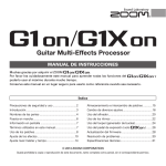
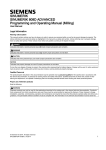
Kramer Electronics, Ltd.
USER MANUAL
Model:
482xl
Bi-directional Audio Transcoder
Contents
Contents
1
2
3
4
5
5.1
6
Introduction
Getting Started
Overview
Your Bi-directional Audio Transcoder
Connecting the Bi-directional Audio Transcoder
Adjusting the Audio Output Level
Technical Specifications
1
1
2
2
4
6
6
Figures
Figure 1: 482xl Bi-directional Audio Transcoder
Figure 2: 482xl Bi-directional Audio Transcoder – Top / Lower Side Panels
Figure 3: 482xl Bi-directional Audio Transcoder Connections
3
3
5
Tables
Table 1: Features and Functions of the 482xl Bi-directional Audio Transcoder
Table 2: Technical Specifications of the 482xl Bi-directional Audio Transcoder
4
6
i
Introduction
1
Introduction
Welcome to Kramer Electronics (since 1981): a world of unique, creative and
affordable solutions to the infinite range of problems that confront the video,
audio and presentation professional on a daily basis. In recent years, we have
redesigned and upgraded most of our line, making the best even better! Our
350-plus different models now appear in 8 Groups1, which are clearly defined
by function.
Congratulations on purchasing your Kramer Tools 482xl Bi-directional Audio
Transcoder. This product is ideal for:
Video and audio production facilities
Audio recording studios
Live sound applications
The package includes the following items:
482xl Bi-directional Audio Transcoder
Power adapter (12V DC Input)
This user manual2
2
Getting Started
We recommend that you:
Unpack the equipment carefully and save the original box and packaging
materials for possible future shipment
Review the contents of this user manual
Use Kramer high performance high resolution cables3
1 GROUP 1: Distribution Amplifiers; GROUP 2: Video and Audio Switchers, Matrix Switchers and Controllers; GROUP 3:
Video, Audio, VGA/XGA Processors; GROUP 4: Interfaces and Sync Processors; GROUP 5: Twisted Pair Interfaces;
GROUP 6: Accessories and Rack Adapters; GROUP 7: Scan Converters and Scalers; and GROUP 8: Cables and Connectors
2 Download up-to-date Kramer user manuals from our Web site: http://www.kramerelectronics.com
3 The complete list of Kramer cables is on our Web site at http://www.kramerelectronics.com
1
Overview
3
Overview
Your 482xl Bi-directional Audio Transcoder has two separate channels that
function independently of each other1:
Converting an unbalanced audio input signal to a balanced2 audio output
signal on one channel
Converting a balanced audio input signal to an unbalanced audio output
signal on the other channel
In addition, the 482xl Bi-directional Audio Transcoder:
Lets you adjust the gain or attenuation while transcoding, to compensate
for the 14dB change between IHF audio levels and the state-of-the-art
balanced DAT input levels
Is designed with very low noise and low distortion components
To achieve the best performance:
Connect only good quality connection cables, thus avoiding interference,
deterioration in signal quality due to poor matching, and elevated noise
levels (often associated with low quality cables)
Use good quality sockets and connectors to avoid signal path breaks3.
Aim for Zero Ohm connection resistance
Avoid interference from neighboring electrical appliances that may
adversely influence signal quality and position your Kramer 482xl away
from moisture, excessive sunlight and dust
4
Your Bi-directional Audio Transcoder
Figure 1, Figure 2 and Table 1 define the 482xl Bi-directional Audio
Transcoder:
1 As both channels function independently, you can use just one channel or both channels simultaneously
2 Balanced audio is more immune to noise and interference
3 Poor quality connectors tend to rust, which may cause breaks
2
KRAMER: SIMPLE CREATIVE TECHNOLOGY
Your Bi-directional Audio Transcoder
Top Side Panel
Lower Side Panel
Figure 1: 482xl Bi-directional Audio Transcoder
Top Side Panel
Lower Side Panel
Figure 2: 482xl Bi-directional Audio Transcoder – Top / Lower Side Panels
3
Connecting the Bi-directional Audio Transcoder
Table 1: Features and Functions of the 482xl Bi-directional Audio Transcoder
#
1
2
3
4
5
6
7
8
Feature
BALANCED IN 5-pin Terminal Block
Connector
UNBAL OUT 3-pin Terminal Block
Connector
UNBAL IN 3-pin Terminal Block
Connector
BALANCED OUT 5-pin Terminal
Block Connector
12V DC
UNBAL
L LEVEL Trimmer
TO BAL
R LEVEL Trimmer
BAL TO
UNBAL
9
10
5
L LEVEL Trimmer
R LEVEL Trimmer
ON LED
Function
Connect to the balanced audio source
Connect to the unbalanced audio
acceptor
Connect to the unbalanced audio source
Connect to the balanced audio acceptor
+12V DC connector for powering the unit
1
Adjust the left balanced audio output
signal level
Adjust1 the right balanced audio output
signal level
Adjust1 the left unbalanced audio output
signal level
1
Adjust the right unbalanced audio output
signal level
Illuminates when receiving power
Connecting the Bi-directional Audio Transcoder
This section describes how you can use the 482xl to convert the unbalanced
audio signal to a balanced audio signal and the balanced audio signal to an
unbalanced audio signal.
To convert the audio input signals at the UNBAL IN2 and the BALANCED
IN3 connectors, as the example illustrated in Figure 3 shows, do the following:
1. Connect the unbalanced audio source (for example, an unbalanced audio
player) to the UNBAL IN 3-pin terminal block connector.
2. Connect the BALANCED OUT 5-pin terminal block connector to the
balanced audio acceptor (for example, a balanced audio recorder).
3. Connect the balanced audio source (for example, a balanced audio player) to
the BALANCED IN 5-pin terminal block connector.
4. Connect the UNBAL OUT 3-pin terminal block connector to the unbalanced
audio acceptor (for example an unbalanced audio recorder).
5. Connect the 12V DC power adapter to the power socket and connect the
adapter to the mains electricity (not shown in Figure 3).
1 Insert a screwdriver into the small hole and carefully rotate it, trimming the appropriate level
2 To the balanced audio output
3 To the unbalanced audio output
4
KRAMER: SIMPLE CREATIVE TECHNOLOGY
Connecting the Bi-directional Audio Transcoder
Balanced
Audio Player
Balanced
Audio
Recorder
Unbalanced
Audio Recorder
Unbalanced
Audio Player
Figure 3: 482xl Bi-directional Audio Transcoder Connections
5
Technical Specifications
5.1 Adjusting the Audio Output Level
The 482xl Bi-directional Audio Transcoder comes factory pre-set for 1:1
transparency1.
To adjust the appropriate audio output levels:
1. Insert a screwdriver into one of the four small holes2 on the lower side of the
482xl Bi-directional Audio Transcoder, enabling access to the appropriate
trimmer.
2. Carefully rotate the screwdriver, adjusting the appropriate audio output level,
as required.
6
Technical Specifications
Table 2 includes the technical specifications3:
Table 2: Technical Specifications of the 482xl Bi-directional Audio Transcoder
INPUTS:
OUTPUTS:
MAX. OUTPUT LEVEL:
BANDWIDTH (-3dB):
CONTROLS:
COUPLING:
THD+NOISE:
2ND HARMONIC:
S/N RATIO:
POWER SOURCE:
DIMENSIONS:
WEIGHT:
ACCESSORIES:
OPTIONS:
1 unbalanced audio stereo on a 3-pin terminal block connector
1 balanced audio stereo on a 5-pin terminal block
1 balanced audio stereo on a 5-pin terminal block connector
1 unbalanced audio stereo on a 3-pin terminal block connector
Balanced: 21dBm; unbalanced: 21dBm@max gain
>100 kHz
-57dB to + 6dB (balanced to unbalanced level); -16dB to
+ 19dB (unbalanced to balanced level)
Balanced to unbalanced: in=AC, out=DC;
Unbalanced to balanced: in=AC, out=DC
0.049%
0.005%
95db/87dB @ balanced to unbalanced/unbalanced to balanced,
unweighted
12 VDC, 190 mA (fully loaded)
12cm x 7.5cm x 2.5cm (4.7" x 2.95" x 0.98"), W, D, H
0.3 kg. (0.66 lbs.) approx.
Power supply, mounting bracket
19" rack adapters RK-T1, RK-T3
1 Readjusting the 482xl Bi-directional Audio Transcoder will upset this transparency. However, if necessary, you can finetune both channels’ audio output levels
2 See Figure 2
3 Specifications are subject to change without notice
6
KRAMER: SIMPLE CREATIVE TECHNOLOGY
LIMITED WARRANTY
Kramer Electronics (hereafter Kramer) warrants this product free from defects in material and workmanship under the
following terms.
HOW LONG IS THE WARRANTY
Labor and parts are warranted for seven years from the date of the first customer purchase.
WHO IS PROTECTED?
Only the first purchase customer may enforce this warranty.
WHAT IS COVERED AND WHAT IS NOT COVERED
Except as below, this warranty covers all defects in material or workmanship in this product. The following are not covered
by the warranty:
1.
2.
3.
Any product which is not distributed by Kramer, or which is not purchased from an authorized Kramer dealer. If you are
uncertain as to whether a dealer is authorized, please contact Kramer at one of the agents listed in the web site
www.kramerelectronics.com.
Any product, on which the serial number has been defaced, modified or removed.
Damage, deterioration or malfunction resulting from:
i)
Accident, misuse, abuse, neglect, fire, water, lightning or other acts of nature
ii)
Product modification, or failure to follow instructions supplied with the product
iii)
Repair or attempted repair by anyone not authorized by Kramer
iv)
Any shipment of the product (claims must be presented to the carrier)
v)
Removal or installation of the product
vi)
Any other cause, which does not relate to a product defect
vii)
Cartons, equipment enclosures, cables or accessories used in conjunction with the product
WHAT WE WILL PAY FOR AND WHAT WE WILL NOT PAY FOR
We will pay labor and material expenses for covered items. We will not pay for the following:
1.
2.
3.
Removal or installations charges.
Costs of initial technical adjustments (set-up), including adjustment of user controls or programming. These costs are the
responsibility of the Kramer dealer from whom the product was purchased.
Shipping charges.
HOW YOU CAN GET WARRANTY SERVICE
1.
2.
3.
To obtain service on you product, you must take or ship it prepaid to any authorized Kramer service center.
Whenever warranty service is required, the original dated invoice (or a copy) must be presented as proof of warranty coverage,
and should be included in any shipment of the product. Please also include in any mailing a contact name, company, address, and
a description of the problem(s).
For the name of the nearest Kramer authorized service center, consult your authorized dealer.
LIMITATION OF IMPLIED WARRANTIES
All implied warranties, including warranties of merchantability and fitness for a particular purpose, are limited in duration to
the length of this warranty.
EXCLUSION OF DAMAGES
The liability of Kramer for any effective products is limited to the repair or replacement of the product at our option. Kramer
shall not be liable for:
1.
2.
Damage to other property caused by defects in this product, damages based upon inconvenience, loss of use of the product, loss
of time, commercial loss; or:
Any other damages, whether incidental, consequential or otherwise. Some countries may not allow limitations on how long an
implied warranty lasts and/or do not allow the exclusion or limitation of incidental or consequential damages, so the above
limitations and exclusions may not apply to you.
This warranty gives you specific legal rights, and you may also have other rights, which vary from place to place.
NOTE: All products returned to Kramer for service must have prior approval. This may be obtained from your dealer.
This equipment has been tested to determine compliance with the requirements of:
EN-50081:
"Electromagnetic compatibility (EMC);
generic emission standard.
Part 1: Residential, commercial and light industry"
EN-50082:
"Electromagnetic compatibility (EMC) generic immunity standard.
Part 1: Residential, commercial and light industry environment".
CFR-47:
FCC Rules and Regulations:
Part 15: “Radio frequency devices
Subpart B – Unintentional radiators”
CAUTION!
Servicing the machines can only be done by an authorized Kramer technician. Any user who makes changes or modifications to
the unit without the expressed approval of the manufacturer will void user authority to operate the equipment.
Use the supplied DC power supply to feed power to the machine.
Please use recommended interconnection cables to connect the machine to other components.
7
For the latest information on our products and a list of Kramer
distributors, visit our Web site: www.kramerelectronics.com,
where updates to this user manual may be found.
We welcome your questions, comments and feedback.
Safety Warning:
Disconnect the unit from the power supply before
opening/servicing.
Caution
Kramer Electronics, Ltd.
Web site: www.kramerelectronics.com
E-mail: [email protected]
P/N: 2900-000134 REV 1