1
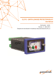
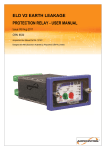
ELM Earth Leakage
Protection Relay
Designed and Manufactured in Australia by
Ampcontrol Pty Limited ACN 000 915 542
Phone: (02) 4956 5899 Fax: (02) 4956 5985
www.ampcontrol.com.au
USER MANUAL
No copies of the information or drawings
within this manual shall be made without
the prior consent of Ampcontrol.
121408 ISSUE 4 15/02/11
ELM_Manual_Issue_4_121408_150211.pdf
ELM USER MANUAL ISSUE 4
Copyright Notice
No part of this publication may be
reproduced, transmitted or transcribed
into any language by any means
without the express written permission
of Ampcontrol Pty Ltd, 250 Macquarie
Road Warners Bay, NSW 2282,
Australia.
Disclaimer
Ampcontrol Pty Ltd will make no
warranties as to the contents of this
documentation
and
specifically
disclaims any implied warranties or
fitness for any particular purpose.
Ampcontrol further reserves the right to
alter the specification of the system
and/or manual without obligation to
notify any person or organisation of
these changes.
Before You Begin
We would like to take a moment to
thank you for purchasing the ELM
Earth Leakage Relay. To become
completely familiar with this equipment
and to ensure correct operation, we
recommend that you take the time to
read this user manual thoroughly.
CRN: 8274
ELM USER MANUAL ISSUE 4
1.
Protection Systems
2.
The Need for Earth Leakage
Protection ...................................... 1
2.1
2.2
2.3
2.4
2.5
2.6
2.7
3.
................... 1
Earth Leakage Systems ............... 2
Methods of Earth leakage
Protection .................................... 2
Core Balance Protection ............. 2
Series Neutral Protection ............ 2
Earth Leakage Toroids ................ 3
Toroid Selection.......................... 3
Toroid Installation Guidelines .... 3
ELM Earth Leakage Relay
3.1
3.2
3.3
3.4
3.5
Description .................................. 4
Methods of Earth Leakage
Protection .................................... 4
Testing Procedure ....................... 4
Toroids ........................................ 4
Mode of Operation ...................... 4
4.
Specifications
5.
Equipment List............................ 5
6.
Diagrams
.............................. 5
ELM Typical Installation Diagram ...... 6
Core Balance E/L System .................... 7
Series Neutral E/L System ................... 8
Mounting Details.................................. 9
CONTENTS
ELM USER MANUAL ISSUE 4
6. Equipment maintained in accordance with
industry standards
1. Protection Systems
Earthing of electrical equipment, associated
machinery and structures is a seemingly simple
practice and is covered adequately by the
various applicable sections of Australian
Standards AS3000 or AS3007.
2. The Need for Earth Leakage
Protection
Unless properly controlled the occurrence of
an earth fault can be hazardous because it may
cause:
However, in the mining industry earthing is
somewhat more complex than normal domestic
or commercial applications and requires other
factors to be taken into consideration
particularly where trailing and/or reeling
cables supply mobile electrical equipment.
a) Frame to earth voltages dangerous to
personnel.
b) Electric arcing, which may initiate an
explosion or fire when arcing occurs in an
underground mining operation.
The protection systems are designed to provide
touch and step potentials of 50 Volts or less
when all the systems are used collectively.
The main purpose of earth fault protection is to
safeguard personnel and electrical apparatus.
However it is found that relays designed to
operate on fault limited systems are not
suitable for personal protection, i.e. users of
portable drills, grinders etc, which require trip
levels of 20-30mA, with instantaneous
operation. (Refer AS3190).
It should be clearly understood that unless all
four types of protection is incorporated in any
design, then personal protection (touch and
step potentials of 50V or less) will need to be
assessed by a competent person or authority.
The protection systems that cover coal and
shale mines are detailed in AS2081, Part 1 to
5. Although these standards do not apply to
metalliferous mining they are a good
benchmark to follow.
The most common apparatus faults in mining
applications are cable faults. Cables are most
susceptible to damage and are the major source
of dangerous electrical incidents. This applies
particularly to the flexible trailing cables
supplying power to mobile mining machines.
Part 1: General requirements for electrical
protection devices for use in coal and
shale mines.
Part 2: Earth Continuity monitoring devices.
Part 3: Earth Leakage protection devices.
Part 4: Lockout Earth fault devices (test
before energisation)
Part 5: Earth Fault Limitation (impedance
earthing)
Cable construction is such as to provide every
phase conductor with an individual conductor
screen so that crushing would cause a low
single phase to earth fault current. The
protective device, such as an Ampcontrol ELM
earth leakage relay, would then isolate the
cable and contain the sparking within the cable
before a heavy short circuit current due to a
phase to phase fault occurs.
The above standards are not a stand-alone
group and have been developed in coordination with other standards being:
Earth fault protection has been applied with
considerable success in limiting faults and
providing quick disconnection of electrical
apparatus from the supply in the event of earth
fault situations.
1. AS1740 – Underground mining
substations
2. AS1802, AS1300 – Reticulation, trailing
and reeling cables
3. AS1299, AS1300 – Plugs, adaptors,
couplers and receptacles
4. Internationally accepted voltage/time
effects on the human body based on
IEC479
5. Installation in accordance with accepted
State and Federal Regulations
A definite time operating characteristic is
provided with adjustable trip sensitivity and
time delay.
Time delay between protective units is
introduced to allow the unit close to the fault to
isolate the faulty circuit without causing the
healthy part of the system to be de-energised.
-1-
ELM USER MANUAL ISSUE 4
The automatic protection of circuits is not
intended to take the place of sound installation
practice and the regular maintenance and
testing of electrical apparatus.
2.1 Earth Leakage Systems
Desirable though it may be, it is impractical to
provide
automatic
protection
against
electrocution as a result of direct contact with a
live conductor, particularly where the electrical
reticulation is exposed to a humid or damp
atmosphere.
Care must be taken in the selection and
installation of all electrical equipment with due
regard to its required duty and the conditions
under which it may be called upon to operate.
Table 1 indicates the current values affecting
human beings.
Current mA
Symptom
1 or less
Causes no sensation - not felt
Sensation of shock, not painful,
individual can let go at will, as
muscular control is not lost
Painful shock, individual can
let go at will, as muscular
control is not lost
Painful shock, muscular
control of adjacent muscles
lost, cannot let go
Painful, severe muscular
contractions, breathing difficult
Ventricular fibrillation (a heart
condition that may result in
death)
1 to 8
8 to 15
15 to 20
20 to 50
50 to 100
(Possible)
100 to 200
(Certain)
200 and over
Where automatic earth leakage protection has
been installed it is essential that its operation
be tested often and to facilitate this a means for
testing is incorporated in all approved earth
leakage relays.
2.2 Methods of Earth Leakage Protection
Earth Leakage Protection Relays for use in
mining applications have to be designed with
reference to AS2081 for use on fault-limited
systems.
There are two methods of protection used.
They are the Core Balance and the Series
Neutral earth leakage protection systems. The
Core Balance relay performs the primary
protection in an installation protecting the
outlet supplying power to a machine. In this
application the time delay is set at
instantaneous. The neutral earth leakage relay
is the back up relay of the installation.
Severe burns, severe muscular
contractions that are so severe
that chest muscles clamp the
heart and stop it for the
duration of the shock. (This
prevents ventricular
fibrillation)
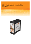
2.3 Core Balance Protection
With this method the three phases are passed
symmetrical through the toroid. If there is no
earth fault present, the vector sum of the
currents in a three-phase supply is zero. If
current from any phase flows to earth the
system becomes unbalanced. The toroid
produces an output, which trips the relay.
Table 1
It will be seen from the foregoing table that the
passage of a current of as low as 15mA
through the human body can cause loss of
muscular control to the extent of preventing
the recipient from disengaging from the live
conductor. Whereas a current in excess of
50mA is sufficient to produce a critical heart
condition from which there is little or no
chance of recovery.
A test current is injected through the window
of the toroid to test the operation of the relay.
See typical circuit, Page 7.
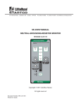
2.4 Series Neutral Protection
With this method the neutral is passed through
the toroid. An earth fault on any of the phase
conductors causes an earth current which
returns, through the toroid, to the star point of
the transformer.
A test circuit can connect a test resistor
between a phase and earth or inject a current
through the toroid as previously described. The
test resistor to earth method is recommended
It follows that as an effective safeguard against
electrocution resulting from direct contact with
a live conductor, it would be necessary to
introduce earth leakage protection designed to
operate with a fault current below 15mA,
which in the majority of cases, would be
impractical.
-2-
ELM USER MANUAL ISSUE 4
with this type of protection as this test also
proves the neutral to earth connection.
See typical circuit, Page 8.
Trying to cram cables into a small space
reduces symmetry and may lead to
problems, which are difficult to solve.
2.5 Earth Leakage Toroids
Toroids (current transformers) are not ideal
devices and if correct procedures are not
followed during installation nuisance tripping
can result. If, for example, we consider a
single-phase earth leakage system where active
and neutral pass through a toroid then at all
times currents in the two wires are equal and
opposite so that the net current through the
toroid is zero. An ideal current transformer
would have all of the flux from each wire
contained in the core and so would accurately
add the opposing fluxes to get a net result of
zero. A real current transformer has “leakage
fluxes”. That is, a very small proportion of the
total flux from each cable is not contained in
the core but in the space outside it and as a
result it may link some turns but not others,
depending on the positioning of the cables. The
effect of this is that a small output may be
obtained from the toroid where none would
arise if the device were ideal.
3. Avoid placing the toroid near any device,
which produces magnetic fields. This
includes bus bars, transformers or other
cables. Try to maintain several toroid
diameters clearance.
4. Many small cables tend to be worse than
say three large ones. Try to position the
toroid in the circuit with this in mind.
5. Toroids used for core balance earth
leakage protection cannot have bus bars
passed through the toroid.
To prevent possible nuisance tripping it is
suggested that the conductor screen of the
earth leakage toroid should be earthed one end
only, the relay end. If both ends are earthed the
possibility exists for the shield to become an
earth loop, having finite resistance and
injecting noise into the toroid leads.
The size of the error may vary from toroids of
the same type because of slight differences in
the core and the symmetry of the winding.
Problems caused in this way increase as the
toroid size increases, as currents increase and
symmetry decreases. Nuisance tripping tends
to occur when the total current rises, such as
when a large motor is started. The following
guidelines would help to avoid such problems.
2.6 Toroid Selection
1. Select the smallest internal diameter
toroid, which will allow the cables to fit
through. Avoid very large toroids
(200mm) or toroids with square apertures.
2. Only use approved toroids specified by
Ampcontrol as these have been designed to
minimise the problem.
2.7 Toroid Installation Guidelines
1. Keep cables as close to the centre of the
toroid as possible. Do not tie them to one
side of the toroid. Remember to aim at
symmetry
2. Do not bring the cables back past the
toroid within one diameter of the toroid.
-3-
ELM USER MANUAL ISSUE 4
3. ELM Earth Leakage Relay
The relay is also suitable for industry where
equipment or system earth leakage protection
is required. The relay is not suitable for
personal protection, which requires trip levels
of 20-30mA, with instantaneous operation.
(Refer AS3190).
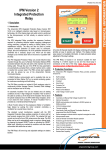
3.1 Description
The Ampcontrol ELM Earth Leakage Relay is
electronic in design and is based on
microprocessor technology. The 'Healthy' LED
flashes to indicate correct operation of the
microprocessor. The Relay uses a toroid to
measure earth fault current. A definite time
operating characteristic is provided with
adjustable trip sensitivity and time delay.
When a fault occurs and the trip level and time
delay is exceeded the relay’s trip function is
activated, operating the trip contacts connected
in the system control circuit. The 'Trip' LED is
'On' when a trip occurs. The trip condition is
latched in non-volatile memory and requires
operation of the reset input to clear the trip
condition. An internal reset is also provided on
the facia of the relay. The 'Relay' LED is 'On'
to indicate the relay is energised.
The ELM Relay continually monitors the
toroid and if the connection is lost the relay
will trip and flash the ‘CT Fault LED’.
3.2 Methods of Earth Leakage Protection
The ELM Relay is suitable for the two
methods of protection used. They are the Core
Balance and Series Neutral earth leakage
protection systems. (See previous section for
details).
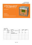
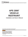
3.3 Testing Procedure
A test current is injected through the window
of the toroid to test the operation of the relay
(See typical connection diagram, Page 6). To
reset the relay press the button located on the
facia of the relay or provide an external
normally open contact (it is recommended that
a twisted pair be used between the N/O contact
and the reset input). The reset button is also
used to access the memory of the processor to
view the maximum level of leakage since the
previous trip. A section of the bar graph will
slow flash (2Hz) indicating the peak level
while, the reset button is held closed and will
continue to flash for 1 second after the reset
button is released.
A ten-segment LED bar graph indicates the %
of leakage level being detected. This reading
can be remotely monitored/displayed using the
4-20mA Output of the Relay. When the relay
measures currents with frequencies much
greater than 50Hz the bar graph LED fast
flashes (5Hz) instead of being steady. Should
the high frequency current persist until the
time delay is exceeded the relay will trip. The
'Har.Trip' LED (Harmonic Trip) is 'On' when a
trip occurs.
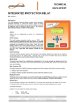
The ELM Earth Leakage Relay is housed in a
stainless steel case and can be either ‘DIN
Rail’ mounted or ‘Panel Mounted’ through a
69 x 39mm cut out. When panel mounted the
front of the ELM Relay is designed to provide
IP-56 ingress protection. There is provision to
prevent unauthorised adjustment of the trip
settings by sealing the post (in front of the
knurled nut) with a lead seal, thus preventing
the removal of the front facia cover.
3. 4 Toroids
The ELM Relay is designed for use with
Ampcontrol EL500S series Toroids. They are
available with window sizes 25, 60 & 85mm.
These allow trip settings from 100mA to 2.5A.
3.5 Mode of Operation
The relay can be operated in fail-safe or nonfail safe modes of operation.
Fail Safe Mode:
This mode is the default and preferred
method, where the relay drops out on fault
or loss of power. Power to the relay is from
the line side of the isolating device or from
an independent supply.
An internal switch mode power supply allows
the ELM to operate from 24VAC to 132VAC
or 20VDC to 185VDC.
The ELM Relay has been designed and tested
for use on fault-limited systems. To ensure
maximum protection the earth leakage system
should be used in conjunction with the other
protection systems covered by AS2081. The
collective systems are designed to limit touch
and step potentials.
Non Fail Safe Mode:
In this mode of operation the relay picks up
on fault. This method should only be used
when the supply to the relay is only
available from the load side of the isolating
-4-
ELM USER MANUAL ISSUE 4
device. To select this mode link the ‘NFS’
input terminals ('NFS' LED is 'On' when
this mode is selected).
5. Equipment List
121398
101399
120255
115438
115439
115440
115441
Note1: To restore power following a trip
condition the reset needs to be held while
re-closing the circuit breaker.
4. Specifications
Relay Supply Volts:
24 –132VAC, 20-185VDC
4-20mA Output:
The ‘Loop Powered’ current output represents
the leakage current as a percentage of the trip
level.
4mA => 0% leakage, 20mA =>120% leakage
(100% = 17.33mA)
Maximum Loop Resistance = [Vs-10] x 50,
where Vs must be greater than 10VDC and less
than 30VDC.
Relay Contacts:
1 N/O, 1 C/O. Rated at 5A 250V, 100VA
maximum.
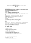
Trip and Time Delay Settings:
Two separate rotary, 16 position switches, set
the trip and time delay parameters of the relay
Switch
Position
0
1
2
3
4
5
6
7
8
9
A
B
C
D
E
F
Trip Level
mA
100
150
200
250
300
350
400
450
500
750
1000
1250
1500
1750
2000
2500
Time Delay
mS
50
100
150
200
250
300
350
400
450
500
750
1000
1500
2000
2500
3000
Dimensions: 47 H x 77 W x 116 D mm
-5-
ELM Earth Leakage Relay
ELD DIN Rail Mounting Kit
ELD-ELC/F Adapter Kit
Toroid - EL500S 25mm ID
Toroid - EL500 / 60mm ID
Toroid - EL500 / 85mm ID
Toroid - EL500 / 112mm ID
ELM USER MANUAL ISSUE 4
Typical Connection Diagram
Incoming
Supply
Remote Monitoring
Output
Alternative Toroid
Position
Relay Contacts
Shown in the
De-energised State
Supply
Transformer
(Optional)
NC-2
10
4-20mA +
Com-2
9
19
4-20mA -
NO-2
8
18
Com-1
7
17
NO-1
6
16
PWR-2
5
110Vac
Test
Circuit
ELM
15
14
Link-3
Earth
3
13
Link-2
CT-com
2
12
Link-1
11
Load
-6-
Non Fail Safe Link
PWR-1
4
CT-sig
1
Toroidal Current
Transformer
Ext Reset
10-30Vdc
PLC Analog Input
or Remote Indication Meter
ELM USER MANUAL ISSUE 4
CORE BALANCE EARTH LEAKAGE
PROTECTION
-7-
SERIES NEUTRAL EARTH LEAKAGE
PROTECTION
-8-