1
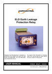
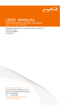
ELD V2 EARTH LEAKAGE PROTECTION RELAY - USER MANUAL Issue: R8 Aug 2011 CRN: 8530 Ampcontrol User Manual Part No: 121581 Designed and Manufactured in Australia by Ampcontrol CSM Pty Limited. ELD V2 EARTH LEAKAGE RELAY Issue: R8, Date: 10/08/2011, CRN: 8530 IMPORTANT! This manual refers to the ELD V2 Relay. A „V2‟ symbol on the fascia of the relay indicates that the ELD relay is version 2 and that this manual is relevant. For other models of the ELD Relay refer to the appropriate ELD Manual; contact Ampcontrol for further details. Safety and other Warnings WARNING! CAUTION! This safety alert symbol identifies important safety messages in this manual and indicates a potential risk of injury or even death to the personnel. When you see this symbol, be alert, your safety is involved, carefully read the message that follows, and inform other operators. This safety alert symbol identifies important information to be read in order to ensure the correct sequence of work and to avoid damage or even destruction of the equipment, and reduce any potential risk of injury or death to the personnel. Supplementary information not directly affecting safety or damage to equipment. Carefully read the message that follows, and inform other relevant personnel. Information concerning possible impact on the environment and actions required for prevention and proper response. ELDB006R8.docx Page 1 ELD V2 EARTH LEAKAGE RELAY Issue: R8, Date: 10/08/2011, CRN: 8530 Copyright Notice No part of this publication may be reproduced, transmitted or transcribed into any language by any means without the express written permission of Ampcontrol CSM Pty Ltd, 7 Billbrooke Close, Cameron Park. NSW 2285, Australia. Disclaimer Ampcontrol CSM Pty Ltd will make no warranties as to the contents of this documentation and specifically disclaims any implied warranties or fitness for any particular purpose. Ampcontrol further reserves the right to alter the specification of the system and/or manual without obligation to notify any person or organisation of these changes. Before You Begin We would like to take a moment to thank you for purchasing the ELD V2 Earth Leakage Relay. WARNING! To ensure the correct and safe operation of this equipment the user is to become completely familiar with the safety requirements and correct operating procedures detailed in this user manual. Ampcontrol Electronics Contact details: Ampcontrol CSM Pty Ltd 7 Billbrooke Close, Cameron Park, NSW, 2285 P +61 2 4903 4800 | F +61 2 4903 4888 EMAIL: [email protected] WEB: www.ampcontrolgroup.com ELDB006R8.docx Page 2 Table of Contents: ELD V2 EARTH LEAKAGE RELAY Issue: R8, Date: 10/08/2011, CRN: 8530 Safety and other Warnings ............................................................................................................................................ 1 Copyright Notice ............................................................................................................................................................ 2 Disclaimer...................................................................................................................................................................... 2 Before You Begin .......................................................................................................................................................... 2 Ampcontrol Electronics Contact details: ........................................................................................................................ 2 1 Receiving and Storage......................................................................................................................................... 4 1.1 Receiving ........................................................................................................................................................ 4 1.2 Storage after Delivery ..................................................................................................................................... 4 1.3 Unpacking of Equipment ................................................................................................................................. 4 2 General Safety ..................................................................................................................................................... 5 2.1 Personnel Safety Warnings ............................................................................................................................. 5 2.1.1 Relevant Personnel ............................................................................................................................. 5 2.1.2 Safety Communication ........................................................................................................................ 5 2.2 Safe Use of Equipment ................................................................................................................................... 5 2.2.1 Changes to Equipment ........................................................................................................................ 5 2.2.2 Equipment Knowledge ........................................................................................................................ 5 3 Overview of Earthing Protection........................................................................................................................... 6 3.1 Protection Systems ......................................................................................................................................... 6 4 The Need for Earth Leakage Protection............................................................................................................... 7 4.1 Overview of Protection Problems .................................................................................................................... 7 4.2 Earth Leakage Systems .................................................................................................................................. 7 4.3 Methods of Earth Leakage Protection ............................................................................................................. 8 4.3.1 Core Balance Protection ..................................................................................................................... 8 4.3.2 Series Neutral Protection .................................................................................................................... 8 4.4 Earth Leakage Toroids .................................................................................................................................... 9 4.4.1 Toroid Selection .................................................................................................................................. 9 4.4.2 Toroid Installation Guidelines .............................................................................................................. 9 5 ELD Earth Leakage Breaker-Operation & Testing ............................................................................................. 10 5.1 Description of Operation ............................................................................................................................... 10 5.2 Methods of Earth Leakage Protection ........................................................................................................... 10 5.3 Testing Procedure ......................................................................................................................................... 11 5.4 Toroids .......................................................................................................................................................... 11 5.5 Mode of Operation ........................................................................................................................................ 11 6 Specifications ..................................................................................................................................................... 11 7 Maintenance & Disposal .................................................................................................................................... 13 7.1 Equipment Maintenance ............................................................................................................................... 13 7.2 Disposal of System Parts .............................................................................................................................. 13 8 Equipment List ................................................................................................................................................... 13 Appendix A – Drawings ............................................................................................................................................... 14 Appendix B – Approvals ................................................................................................ Error! Bookmark not defined. ELDB006R8.docx Page 3 1 Receiving and Storage ELD V2 EARTH LEAKAGE RELAY Issue: R8, Date: 10/08/2011, CRN: 8530 1.1 Receiving All possible precautions are taken to protect the equipment against damage or losses during shipment, however before accepting delivery, check all items against the packing list or Bill of Landing. If there are shortages or evidence of physical damage, notify Ampcontrol immediately. Notify Ampcontrol within 7 days (maximum) in case of shortages or discrepancies, according to the packing list. This action will help ensure a speedy resolution to any perceived problems. Keep a record of all claims and correspondence. Photographs are recommended. Where practicable do not remove protective covers prior to installation unless there are indications of damage. Boxes opened for inspection and inventory should be carefully repacked to ensure protection of the contents or else the parts should be packaged and stored in a safe place. Examine all packing boxes, wrappings and covers for items attached to them, especially if the wrappings are to be discarded. 1.2 Storage after Delivery Where equipment is not to be installed immediately, proper storage is important to ensure protection of equipment and validity of warranty. All equipment should be stored indoors protected from the elements in a cool dry area. If storing on the ground, ensure that the storage area is not an area where water will collect. 1.3 Unpacking of Equipment The method of packing used will depend on the size and quantity of the equipment. The following cautions should be interpreted as appropriate. CAUTION! Take care when unpacking crates as the contents may have shifted during transport. Make sure that cable drums are securely attached to their shipping pallets before attempting to move them (if applicable). The disposal of packaging materials, replaced parts, or components must comply with environmental restrictions without polluting the soil, air or water. Ensure that any timber and cardboard used as packaging is disposed of in a safe and environmentally responsible manner. Where possible, dispose of all waste products i.e. oils, metals, plastic and rubber products by using an approved recycling service centre. ELDB006R8.docx Page 4 2 General Safety ELD V2 EARTH LEAKAGE RELAY Issue: R8, Date: 10/08/2011, CRN: 8530 2.1 Personnel Safety Warnings 2.1.1 Relevant Personnel Ensure all personnel directly responsible or involved with the installation, operation and maintenance of the equipment reference this manual in conjunction with any relevant risk assessments to identify all foreseeable hazards. 2.1.2 Safety Communication All safety instructions and design requirements within this manual must be communicated to all users. These requirements are necessary to identify and control any foreseeable risk associated with this piece of equipment. In the event of any damage or malfunction that results in the potential to harm the health or safety of any person; the owner/operator should notify the manufacturer immediately. 2.2 Safe Use of Equipment Equipment supplied has been manufactured within the guide lines of the relevant Australian Standards and state legislative requirements. Equipment identified within this manual has been designed for a specific intended purpose; therefore any modification or damage must be reported to the manufacturer for repair. The instructions within this manual must be observed as an aid towards achieving maximum safety during operation. 2.2.1 Changes to Equipment Changes in the design and modifications to the equipment are not permitted 2.2.2 Equipment Knowledge Experience with, or understanding of, this equipment is essential for the safe installation and removal of the equipment. If in doubt, contact Ampcontrol immediately. Mechanical and or Electrical installation, and maintenance of plant and equipment, must only be carried out by appropriately trained, qualified and competent personnel. ELDB006R8.docx Page 5 3 Overview of Earthing Protection ELD V2 EARTH LEAKAGE RELAY Issue: R8, Date: 10/08/2011, CRN: 8530 3.1 Protection Systems Earthing of electrical equipment, associated machinery and structures is a seemingly simple practice and is covered adequately by the various applicable sections of Australian Standards AS3000 or AS3007. However, in the mining industry earthing is somewhat more complex than normal domestic or commercial applications and requires other factors to be taken into consideration particularly where trailing and/or reeling cables supply mobile electrical equipment. The protection systems are designed to provide touch and step potentials of 50 Volts or less when all the systems are used collectively. It should be clearly understood that unless all four types of protection is incorporated in any design, then personal protection (touch and step potentials of 50V or less) will need to be assessed by a competent person or authority. The protection systems that cover coal, shale mines and metalliferous mining are detailed in AS/NZS 2081. Section 1, 2 and 3: General requirements for electrical protection devices for use in coal and shale mines. Section 5: Earth Continuity monitoring devices. Section 6: Earth Leakage protection devices. Section 7: Lockout Earth fault devices (test before energization) Section 4: Earth Fault Limitation (impedance earthing) Section 9: Frozen Contact Protection Devices The above standards are not a stand-alone group and have been developed in co-ordination with other standards being: AS1740 – Underground mining substations. AS1802, AS1300 - Reticulation, trailing and reeling cables. AS1299, AS1300 - Plugs, adaptors, couplers and receptacles. AS/NZS 4871 – Electrical Equipment For Mines And Quarries Internationally accepted voltage/time effects on the human body based on IEC479. Instructions for installation in accordance with accepted State and Federal Regulations. Equipment maintained in accordance with industry standards. ELDB006R8.docx Page 6 4 The Need for Earth Leakage Protection ELD V2 EARTH LEAKAGE RELAY Issue: R8, Date: 10/08/2011, CRN: 8530 4.1 Overview of Protection Problems Unless properly controlled the occurrence of an earth fault can be hazardous because it may cause: Frame to earth voltages dangerous to personnel. Electric arcing, which may initiate an explosion or fire when arcing occurs in an underground mining operation. The main purpose of earth fault protection is to safeguard personnel and electrical apparatus. However it is found that relays designed to operate on fault limited systems are not suitable for direct personal protection, i.e. users of portable drills, grinders etc, which require trip levels of 20-30mA, with instantaneous operation. (Refer AS/NZS 3190). The most common apparatus faults in mining applications are cable faults. Cables are most susceptible to damage and are the major source of dangerous electrical incidents. This applies particularly to the flexible trailing cables supplying power to mobile mining machines. Cable construction is such as to provide every phase conductor with an individual conductor screen so that crushing would cause a low single phase to earth fault current. The protective device, such as an Ampcontrol ELD earth leakage relay, would then isolate the cable and contain the sparking within the cable before a heavy short circuit current due to a phase to phase fault occurs. Earth fault protection has been applied with considerable success in limiting faults and providing quick disconnection of electrical apparatus from the supply in the event of earth fault situations. A definite time operating characteristic is provided with adjustable trip sensitivity and time delay. Time delay between protective units is introduced to allow the unit close to the fault to isolate the faulty circuit without causing the healthy part of the system to be de-energised. 4.2 Earth Leakage Systems Desirable though it may be, it is impractical to provide automatic protection against electrocution as a result of direct contact with a live conductor, particularly where the electrical reticulation is exposed to a humid or damp atmosphere. Table 4.2 (taken from IEC Standards) indicates the current values affecting human beings. Current mA Symptom 1 or less Causes no sensation - not felt 1 to 8 Sensation of shock, not painful, individual can let go at will, as muscular control is not lost 8 to 15 Painful shock, individual can let go at will, as muscular control is not lost 15 to 20 Painful shock, muscular control of adjacent muscles lost, cannot let go 20 to 50 Painful, severe muscular contractions, breathing difficult 50 to 100 (Possible) 100 to 200 (Certain) Ventricular fibrillation (a heart condition that may result in death) 200 and over Severe burns, severe muscular contractions; so severe that chest muscles clamp the heart and stop it for the duration of the shock. (This prevents ventricular fibrillation) ELDB006R8.docx Page 7 ELD V2 EARTH LEAKAGE RELAY Issue: R8, Date: 10/08/2011, CRN: 8530 It can be seen from the previous table (Table 4.2) that the passage of a current of as low as 15mA through the human body can cause loss of muscular control to the extent of preventing the recipient from disengaging from the live conductor. Whereas a current in excess of 50mA is sufficient to produce a critical heart condition from which there is little or no chance of recovery. It follows that as an effective safeguard against electrocution resulting from direct contact with a live conductor, it would be necessary to introduce earth leakage protection designed to operate with a fault current below 15mA, which in the majority of cases, would be impractical. The automatic protection of circuits is not intended to take the place of sound installation practice and the regular maintenance and testing of electrical apparatus. Care must be taken in the selection and installation of all electrical equipment with due regard to its required duty and the conditions under which it may be called upon to operate. Where automatic earth leakage protection has been installed it is essential that its operation be tested often and to facilitate this, a means for testing is incorporated in all approved earth leakage relays. 4.3 Methods of Earth Leakage Protection Earth Leakage Protection Relays for use in mining applications have to be designed and tested to AS/NZS 2081.32002 for use on fault limited systems. There are two methods of protection used. They are the Core Balance and the Series Neutral earth leakage protection systems. The Core Balance relay performs the primary protection in an installation protecting the outlet supplying power to a machine. In this application the time delay is set at instantaneous. The neutral earth leakage relay is the backup relay of the installation and can have a time delay up to a maximum of 500mS. 4.3.1 Core Balance Protection With this method the three phases are passed symmetrically through the toroid. If there is no earth fault present, the vector sum of the currents in a three-phase supply is zero. If current from any phase flows to earth the toroid flux becomes unbalanced. The toroid produces an output, which trips the relay. A test current is injected through the window of the toroid to test the operation of the relay. See typical circuit, Page 16 - Drawings. 4.3.2 Series Neutral Protection With this method the neutral is passed through the toroid. An earth fault on any of the phase conductors causes an earth current which returns, through the toroid, to the star point of the transformer. A test circuit can connect a test resistor between a phase and earth or inject a current through the toroid as previously described. The test resistor to earth method is recommended with this type of protection as this test also proves the neutral to earth connection. See typical circuit, Page 16 - Drawings. ELDB006R8.docx Page 8 4.4 Earth Leakage Toroids ELD V2 EARTH LEAKAGE RELAY Issue: R8, Date: 10/08/2011, CRN: 8530 Toroids (current transformers) are not ideal devices and if correct procedures are not followed during installation nuisance tripping can result. If, for example, we consider a single-phase earth leakage system where active and neutral pass through a toroid then at all times currents in the two wires are equal and opposite so that the net current through the toroid is zero. An ideal current transformer would have all of the flux from each wire contained in the core and so would accurately add the opposing fluxes to get a net result of zero. A real current transformer has “leakage fluxes”. That is, a very small proportion of the total flux from each cable is not contained in the core but in the space outside it and as a result it may link some turns but not others, depending on the positioning of the cables. The effect of this is that a small output may be obtained from the toroid where none would arise if the device were ideal. The size of the error may vary from toroids of the same type because of slight differences in the core and the symmetry of the winding. Problems caused in this way increase as the toroid size increases, as currents increase and symmetry decreases. Nuisance tripping tends to occur when the total current rises, such as when a large motor is started. The following guidelines would help to avoid such problems. 4.4.1 Toroid Selection i. Select the smallest internal diameter toroid, which will allow the cables to fit through. Avoid very large toroids (200mm) or toroids with square apertures. ii. Only use approved toroids specified by Ampcontrol as these have been designed to minimise the problem. 4.4.2 Toroid Installation Guidelines i. Keep cables as close to the centre of the toroid as possible. Do not tie them to one side of the toroid. Remember to aim at symmetry ii. Do not bring the cables back past the toroid within one diameter of the toroid. Trying to cram cables into a small space reduces symmetry and may lead to problems, which are difficult to solve. iii. Avoid placing the toroid near any device, which produces magnetic fields. This includes bus bars, transformers or other cables. Try to maintain several toroid diameters clearance. iv. Many small cables tend to be worse than say three large ones. Try to position the toroid in the circuit with this in mind. v. Toroids used for core balance earth leakage protection cannot have bus bars passed through the toroid. vi. To prevent possible nuisance tripping it is suggested that the conductor screen of the earth leakage toroid should be earthed one end only, the relay end. If both ends are earthed the possibility exists for the shield to become an earth loop, having finite resistance and injecting noise into the toroid leads. CAUTION! The ELD relay includes a circuit for continually testing the toroid connection. The resistance of the wiring between the relay and toroid must be kept below 1ohm. If this is not done then a “CT” fault will be detected and the relay will trip. ELDB006R8.docx Page 9 ELD V2 EARTH LEAKAGE RELAY Issue: R8, Date: 10/08/2011, CRN: 8530 5 ELD Earth Leakage Breaker-Operation & Testing 5.1 Description of Operation The Ampcontrol ELD V2 Earth Leakage Relay is electronic in design and is based on microprocessor technology. The „Healthy‟ LED flashes to indicate correct operation of the microprocessor. The Relay uses a toroid to measure earth fault current. A definite time operating characteristic is provided with adjustable trip sensitivity and time delay. When a fault occurs and the trip level and time delay is exceeded the relay‟s trip function is activated, which operates the trip contacts connected in the system control circuit. The trip „LED‟ is „On‟ when a trip occurs. The trip condition is latched in non-volatile memory and requires operation of the reset input to clear the trip condition. An internal reset is also provided on the facia of the relay. The „relay‟ LED is „On‟ to indicate the relay is energised. A ten-segment LED bar graph indicates the % of leakage level being detected. This reading can be remotely monitored/displayed using the 4-20mA Output of the Relay. When the relay measures currents with frequencies much greater than 50Hz, the bar graph LED fast flashes (5Hz) instead of being steady. Should the high frequency current persist until the time delay is exceeded the relay will trip and the „Har.Trip‟ LED (Harmonic Trip) will be illuminated. The ELD V2 Earth Leakage Relay is housed in a stainless steel case and can be either „DIN Rail‟ mounted or „Panel Mounted‟ through a 69 x 39mm cut out. When panel mounted the front of the ELD Relay is designed to provide IP56 ingress protection. There is provision to prevent unauthorised adjustment of the trip settings by sealing the post (in front of the knurled nut) with a lead seal, thus inhibiting the unauthorized removal of the front fascia cover. An internal switch mode power supply allows the ELD to operate from 25.6VAC to 132VAC or 20VDC to 185VDC. The ELD V2 Relay has been designed and tested for use on fault-limited systems. To ensure maximum protection the earth leakage system should be used in conjunction with the other protection systems covered by AS/NZS 2081. The collective systems are designed to limit touch and step potentials. The relay is also suitable for industry where equipment or system earth leakage protection is required. The relay is not suitable for personal protection, which requires trip levels of 20-30mA, with instantaneous operation. (Refer AS/NZS 3190). The ELD Relay continually monitors the toroid and if the connection is lost the relay will trip and flash the „CT Fault LED‟. See following Caution: CAUTION! The ELD relay includes a circuit for continually testing the toroid connection. The resistance of the wiring between the relay and toroid must be kept below 1ohm. If this is not done then a “CT” fault will be detected and the relay will trip. 5.2 Methods of Earth Leakage Protection The ELD V2 Relay is suitable for the two methods of protection used. They are the Core Balance and Series Neutral earth leakage protection systems. (See Section 4.3, Methods of Earth Leakage Protection, for details). ELDB006R8.docx Page 10 5.3 Testing Procedure ELD V2 EARTH LEAKAGE RELAY Issue: R8, Date: 10/08/2011, CRN: 8530 A test current is injected through the window of the toroid to test the operation of the relay (See typical connection diagram on page 16Appendix A – Drawings). To reset the relay: press the button located on the facia of the relay, or provide an external normally open contact. (It is recommended that a twisted pair be used between the N/O contact and the reset input). The reset button is also used to access the memory of the processor to view the maximum level of leakage since the previous trip. A section of the bar graph will slow flash (2Hz) indicating the peak level while the reset button is held closed, and will continue to flash for 1 second after the reset button is released. 5.4 Toroids The ELD V2 Relay is designed for use with Ampcontrol EL500S series Toroids. They are available with window sizes 25, 60, & 112mm. These allow trip settings from 100mA to 2500mA. 5.5 Mode of Operation To comply with AS/NZS 2081.3:2002 the relay can only be operated in the fail-safe mode. This is the default mode, where the relay drops out on fault or loss of power. Power to the relay is from the line side of the isolating device or from an independent supply. 6 Specifications Relay Supply Volts: 25.6 –132VAC, 20-185VDC Power Consumption Approx. 4VA 4-20mA Output: The „Loop Powered‟ current output represents the leakage current as a percentage of the trip level. 4mA => 0% leakage, 20mA =>120% leakage (100% = 17.33mA) Maximum Loop Resistance = [Vs-10] x 50, where Vs must be greater than 10VDC and less than 30VDC. 4 – 20mA accuracy ± 2% of full scale. Relay Contacts: 1 N/O, 1 C/O. Rated at 5A 250V. Relay to Toroid Loop resistance < 1 ohm Dimensions: Overall: Cut-out: ELDB006R8.docx 77 W x 47 H x 116 D mm 69 W x 39 H mm Page 11 ELD V2 EARTH LEAKAGE RELAY Issue: R8, Date: 10/08/2011, CRN: 8530 Trip and Time Delay Settings: * Two separate rotary, 16 position switches, set the trip and time delay parameters of the relay Switch Position Trip Level mA Time mS 0 100 50 1 150 100 2 200 150 3 250 200 4 300 250 5 350 300 6 400 350 7 450 400 8 500 450 9 750 500 A 1000 500 B 1250 500 C 1500 500 D 1750 500 E 2000 500 F 2500 500 Delay * Read the following warning: WARNING! The above table refers to Version 2 of the ELD Relay, designed and tested to AS/NZS 2081.3:2002. Switch positions 9 to F have been modified from the Version 1 relay to comply with the 2002 version of the standard. Verify you have the correct version of the relay by checking that „V2‟ is printed on the fascia, as shown in the image on the front cover of this document, before selecting positions 9 to F of this table. ELDB006R8.docx Page 12 ELD V2 EARTH LEAKAGE RELAY Issue: R8, Date: 10/08/2011, CRN: 8530 7 Maintenance & Disposal 7.1 Equipment Maintenance WARNING! The ELD has no user serviceable parts. All repairs must be carried out by Ampcontrol personnel only. If a fault develops return the ELD to Ampcontrol for repair. It is essential that no attempt be made to repair the ELD as any attempt to dismantle or repair the ELD can seriously compromise the safety of the unit and the consequence can be fatal. The ELD V2 Earth Leakage Protection Relay does not have any customer serviceable parts and is not provided with any user adjustments. 7.2 Disposal of System Parts The electronic equipment discussed in this manual must not be treated as general waste. By ensuring that this product is disposed of correctly you will be helping to prevent potentially negative consequences for the environment and human health which could otherwise be caused by incorrect waste handling of this product. 8 Equipment List 115161 101399 120255 115437 115637 101656 ELD V2 Earth Leakage Relay ELD DIN Rail Mounting Kit ELD ELC/F Adaptor Kit Toroid 25 mm ID Toroid 60 mm ID Toroid 112 mm ID 144756 Toroid 300mm ID 121581 ELD V2 User Manual ELDB006R8.docx Page 13 ELD V2 EARTH LEAKAGE RELAY Issue: R8, Date: 10/08/2011, CRN: 8530 Appendix A – Drawings Drawing Number Description ELDA001 General Arrangement with Cut-out Details ELDE002 Typical Connection Diagram The drawings appear in the following pages in the same order in which they are listed in the table above. ELDB006R8.docx Page 14 ELD V2 EARTH LEAKAGE RELAY Issue: R8, Date: 10/08/2011, CRN: 8530 ELDB006R8.docx Page 15 ELD V2 EARTH LEAKAGE RELAY Issue: R8, Date: 10/08/2011, CRN: 8530 ELDB006R8.docx Page 16 ELD V2 EARTH LEAKAGE RELAY Issue: R8, Date: 10/08/2011, CRN: 8530 ELDB006R8.docx Page 17 ELD V2 EARTH LEAKAGE RELAY Issue: R8, Date: 10/08/2011, CRN: 8530 CAUTION! The ELD relay includes a circuit for continually testing the toroid connection. The resistance of the wiring between the relay and toroid must be kept below 1ohm. If this is not done then a “CT” fault will be detected and the relay will trip. ELDB006R8.docx Page 18