1
Institute for Software Integrated Systems
Vanderbilt University
Nashville Tennessee 37235
TECHNICAL REPORT
TR #: ISIS-04-503
Title: Embedded Software Composition and Verification
Authors: P. Volgyesi, M. Maroti, S. Dora, E. Osses, A. Ledeczi, T. Paka
Copyright © 2004 Vanderbilt University
Embedded Software Composition and
Verification
Abstract. Developing networked embedded systems involves reasoning
about complex interactions between software modules, including operating system and middleware services and application-specific components, various hardware units and the environment. Component-based
design addresses this challenge by allowing engineers to partition the
embedded application into several components along well-defined interfaces. The interface specification formalism is of crucial importance in
supporting isolated component development and testing. We propose a
hierarchical interface automaton language for the design of embedded
software components and applications. The formalism allows the specification of structural, as well as behavioral aspects of components. The
paper develops automated analysis techniques for asserting compatibility
and composability of embedded software components. A prototype modeling environment and integrated verification tools targeting TinyOS, a
representative embedded operating system, are also presented.
1
Introduction
Networked embedded systems constitute a relatively new category of systems
that necessitates the development and application of novel systems and software
engineering techniques. These systems are tightly coupled to physical processes
and distributed across a relatively large number of processing nodes often having
limited resources and communication capabilities. The highly distributed nature
of computing in networked embedded systems implies that each node must be
equipped with a sophisticated middleware—a distributed operating system that
provides global services for the applications. The middleware layer is a key ingredient of these systems: it encapsulates services that are reusable across a number
of specific problems, yet independent of the underlying hardware infrastructure,
which is managed by the operating system.
The middleware is expected to support various coordination services beyond
basic communication protocols. Coordination services range from simple eventand time-based coordination to complex algorithms for leader election, spanning tree formation, protocols for distributed consensus, distributed transactions, group communication services, clock synchronization. Because of resource
limitations, a complex, monolithic middleware layer that contains all services for
all applications is not feasible. Rather, an approach is needed that can configure
only the required services into the middleware.
Component based design can address these requirements. The advantages of
using components stem from the fact that they can be developed and tested in
isolation, and systems can be built and updated incrementally. Designed with
adequate generality, components can be reused in different applications. Furthermore, building the middleware layer from components makes it possible to
include only the services needed by the application conserving precious system
resources.
TinyOS [2], an operating system designed specifically for networked embedded systems, extends this approach to the operating system level. Even the most
basic system modules of TinyOS are regular components that can be augmented
or replaced for different applications and/or platforms. nesC, the implementation
language of TinyOS [5], defines a component model that relies on bidirectional
interfaces and enables an efficient implementation that avoids dynamic component creation. TinyOS applications are statically linked graphs of event-driven
components.
Real-world networked embedded systems are built from hundreds of components interacting through various interfaces. Manual wiring of components, a
tedious and error prone task in nesC, can be automated by composition tools,
such as Gratis [4]. However, the truly challenging, yet critical ingredient for the
development of large scale applications is the automatic verification of component composition.
Most programming errors during application composition are either the result
of incorrectly used components or the bad interaction of multiple components,
some of which could be operating system components not even developed by
the user. We address these sources of programming errors by introducing a formalism for interface specification based on the Interface Automata language.
A prototype modeling environment and integrated verification tool for TinyOS
applications is also presented.
In the following sections an overview of TinyOS and the baseline modeling environment is presented. Then the formalism for modeling component interfaces
is defined. Next the composition and compatibility verification of hierarchical
interface automata is described. How these automata can be used to validate
existing hand-written components, as well as assemblies of components, is presented afterwards. Finally, the use of the proposed formalism and verification
tools are illustrated through a case study.
2
TinyOS
TinyOS is a component-based configurable operating system with a very small
footprint specifically designed for severely resource constrained devices such as
the nodes in a typical networked embedded systems [2]. TinyOS is a graph of
software components implementing the basic functionalities that an application
might need, such as basic I/O, timers, wireless communication etc. Each application consists of application-specific components, written by the application designer, and a subset of the TinyOS components. This way an application-specific
TinyOS instance is created for each application providing only the services the
application needs, which conserves system resources.
A TinyOS application is a hierarchical graph of components that is scheduled
by a simple FIFO-based non-preemtive scheduler. Components communicate
with each other through commands and events, which are executed immediatelly
via function calls. Commands propagate downward; they are issued by higher
level components to lower level ones. Events propagate upward; they are signaled
by lower level components and handled by higher level ones. Events at the lowest
level are generated by the hardware itself in the form of interrupts. Commands
at the highest level are initiated by tasks. Tasks are intended to perform a
short amount of processing and return control to the scheduler. They can only
be preempted by hardware events not by other tasks. This task model enables
TinyOS to have a single call stack.
The latest version of TinyOS (version 1.1) is implemented in nesC [5]. nesC,
an extension of C, is developed specifically to support the TinyOS model of
computation. It disallows dynamic memory allocation and dynamic dispatch
making nesC programs statically analyzable and optimizable.
The three major building blocks of a nesC application are interfaces, modules
and configurations. An interface is a set of related events and/or commands. In
other words, an interface is a set of function declarations. The provider of an
interface must implement the commands, while the user of the interface must
implement the events.
Modules and configurations are both components. Modules are the elementary building blocks; they have procedural nesC code associated with them to
specify their functionality. Configurations are the composite components; they
contain modules and/or other configurations and the wiring specification connecting the various interfaces of the contained components together. Every nesC
(and TinyOS) application has a single top level configuration [5].
3
Gratis
A TinyOS application is a hierarchical component assembly where interface declarations, module implementations and component configurations, i.e. wiring
specifications, are specified in numerous text files. Graphical representation of
the same information increases the readability and understandability of the application architecture and helps in avoiding configuration errors, such as the
omission of the wiring specification of one or more interfaces of a component.
The Graphical Development Environment for TinyOS (Gratis) is a typical
application of Model Integrated Computing (MIC) in general, and the Generic
Modeling Environment (GME), in particular [3]. GME is a metaprogrammable
toolkit for creating domain-specific modeling environments. GME metamodels
specify the modeling language of the application domain. They are used to automatically configure GME for the domain, that is, to create a modeling environment that has native support of the target modeling language.
GME models take the form of graphical, multi-aspect, attributed entityrelationship diagrams. Their syntax is defined by the metamodels specified in
a UML class diagram-based notation. The static semantics of a model are augmented by OCL constraints [8] that are also part of the metamodels. They are
enforced by a built-in constraint manager during model building time. The dynamic semantics are applied by the model interpreters, i.e. by the process of
translating the models to source code, configuration files, database schema or
any other artifact the given application domain calls for.
This approach fits component-based software development very nicely. The
interface of the individual components can be modeled along with a link to their
implementation. The model editor can enforce the composition rules to make sure
that only valid component assemblies are allowed. More sophisticated analysis
can be performed by interfacing to outside tools. Finally, model interpreters can
generate the glue code that ties the final system together.
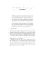
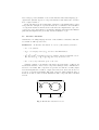
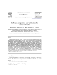
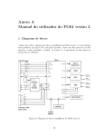
Fig. 1. The simplified metamodel of Gratis
The simplified metamodel of Gratis defines the mapping of TinyOS concepts
to GME concepts, as shown in Fig. 1. The three basic building blocks of Gratis
models are interfaces, modules and configurations. An interface consists of a set
events and commands. Both events and commands are functions. The return
type is captured by a textual attribute, while the arguments are modeled with
contained objects each having its own type declaration. A module contains a set
of interface references (interface ref) and its nesC code as a textual attribute.
A reference is a graphical object that points to another object contained elsewhere in the model hierarchy. This is captured in the metamodel by a directed
connection pointing from the interface to the interface ref metamodel in Fig. 1.
Interfaces are declared at the global level and modules do not contain them directly; they just refer to their declaration through the use of references. This
allows multiple modules using and/or implementing the same interface declarations. Also, when an interface needs to be modified, it is done at one place
and all interface references in all components will refer to the updated interface
automatically.
Similarly, configurations contain references to interfaces, modules (module ref)
and other configurations (configuration ref). Interface references contained in
modules and configurations appear as ports in higher level configurations. Component wiring specifications are expressed in Gratis as connections between interfaces and/or interface ports in configurations. In fact, two different kinds of
connections are used in configurations. A LINK specifies that a component uses
and another provides an interface. An EQUTE connection specifies that the interface the given configuration uses/provides is delegated down to a contained
component that either implements it or delegates it further down the component
hierarchy. Fig. 2 depicts an example application modeled in Gratis illustrating
these concepts, which was originally introduced in [5].
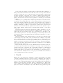
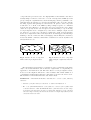
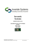
Fig. 2. Top level model of the Surge application in Gratis.
This application preiodically samples a photo sensor and reports the measured readings to a base station. The communication is based on ad-hoc multihop routing over the wireless network, where the nodes organize themselves into
a spanning tree rooted at the base station. Each node maintains the address of its
parent in the tree, advertising its depth in each radio message that it transmits.
A node selects its parent by listening to messages and choosing the node with
the smallest depth; to seed the creation of the spanning tree, the base station
periodically broadcasts beacon messages with depth 0 [5]. The entire routing
logic is implemented by the MultiHop component and hidden from the applica-
tion developer. The routing block itself is a composite component, which uses
the MultiHopSend, MultiHopRoute and MultiHopRouteSelect sub-components.
At the top level the participating components are Main, the standard entry
point of all applications in TinyOS, TimerC, the abstraction layer of hardware
timers, Photo, the photo sensor driver, MultiHop, the previously mentioned communication service provider, Leds, the hardware LED driver, and SurgeM, the
sole application specific module. Module and configuration components are depicited in dark and light colors, respectively. The ports of components are the
provided and used interfaces. This example will be used throughout the paper.
The only information captured textually in Gratis is the procedural code of
module implementations. The model interpreter generates all the nesC files containing interface, module and configuration specifications automatically. Keeping
the graphical models and the corresponding nesC files in synch is a challenge,
especially because a large code base of TinyOS components exists in text form
only. Therefore, the Gratis model interpreter is bi-directional; not only does it
generate the nesC files from graphical models, but it is also capable of parsing existing source files and building the corresponding models automatically.
The main use of this parsing feature is to automatically generate the graphical
equivalent of the TinyOS system components and to provide them as a library
to the user in the Gratis environment. This library can then be refreshed when
new TinyOS releases become available without any modifications to existing
graphical application models.
4
Temporal Models of Component Interfaces
Traditional programming languages and interface description methods—such as
CORBA or COM IDL—capture only the type aspects of software components.
The access points of a given component are enumerated along with their accepted
and returned parameter types in terms of values and domains. TinyOS and its
implementation language nesC [5] is no exception to this: component interfaces
are defined by a set of function declarations. Compatibility checking provided by
compilers guarantees that the user of a function provides the required parameters
and handles the returned value in a type-safe manner.
Even in trivial applications, the access points of a software component are
not isolated, dependencies and complex relationships might impose additional
constraints on the use of their services. Typical patterns—such as initialization
before use—can be found in almost every component. A component providing
communication services may have more sophisticated restrictions that are inherent in the communication protocol. Even if the legal order and dependencies of
the function calls are described in the documentation of the component as informal rules, automatic tools and formal methods cannot verify these constraints.
Graphical models of traditional interfaces enable us to understand and build
complex applications, however, they do not extend the information captured
in the textual representation. Effective composition and reuse of software components demands deeper understanding and specification of component inter-
faces. Our proposed formalism—based on the Interface Automata language [1]—
captures the dynamic aspects of component interfaces and enables us to describe
more complex behavior.
In the following sections, formal rules of interface compatibility will be given
along with the description of practical methods for verification and validation
of component interfaces and interaction. We have also implemented a proof-ofconcept prototype environment of our interface language that targets the TinyOS
platform and augments the previously described Gratis tool [4].
4.1
Interface Automata
Our interface modeling language is based on the definition of Interface Automaton, which we will reproduce here.
Definition 1. An interface automaton P consists of the following elements:
– SP , a set of states,
– SPinit , a nonempty subset of SP , known as the initial states,
H
– AIP , AO
P and AP , mutually disjoint sets of input, output and internal actions.
H
We denote by AP = AIP ∪ AO
P ∪ AP the set of all actions, and
– TP , a set of steps, where TP ⊆ SP × AP × SP .
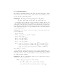
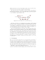
A simple example of an interface automaton is given in Fig. 3. The model
describes the interface of the Comm component, which provides communication
services to its clients. The component accepts the init and the sendM sg input
actions and signals the sendDone output action. However, these actions are not
accepted or generated arbitrarily. The legal orders are defined with the help of
states s0, s1 and s2, where s0 is the initial state. The component has no internal
actions.
init?
s0
sendMsg?
s1
s2
sendDone!
init
sendMsg
sendDone
Fig. 3. The Interface Automaton Comm
A trivial compatible component App can be constructed by replicating the
states and steps of component Comm, but inverting the direction of its actions,
thus input actions in Comm become output actions in App and vice versa. In
their composition, the two automata are advancing together step by step, always
transmitting or receiving an action that is accepted or sent by the other.
In general, the cross-product of the set of states in the original components
generates the state space of the composite automaton. A step in the product
might be either a shared step, which advances both of the original automata
together—as we have seen in the previous paragraph, or an independent step in
one of the building blocks.
Compatibility analysis must focus on composite states, where one of the
original automata initiates a shared step, but the other component is not prepared for accepting this action in its respective state. We denote these composite
states as illegal states. There are two basic approaches to handle illegal states
with respect to compatibility. The “pessimistic” approach defines two components incompatible, if any illegal state is reachable in their composition, i.e. there
exists a sequence of steps whose first state is one of the initial composite states
and whose last state is the illegal state. The “optimistic” approach considers
two components compatible if there is some environment—a third automaton—
under which the composite automaton behaves correctly.
The pessimistic approach demands strict compatibility, and it guarantees
that independently of additional components, the verified modules will work
together correctly. When the product system is closed—each action is internal—
the pessimistic and optimistic approaches coincide. In this paper we are following
the pessimistic approach; detailed discussion of the optimistic method can be
found in [1].
4.2
Hierarchical Interface Automata
Interface Automata have similar limitations to Finite State Machines: in their
flat form both languages have problems with describing complex behavior and
state space. We propose additional constructs to the original automata language
to overcome these problems.
In embedded applications external events from the physical environment
might arrive in any moment regardless of the current state of the application.
These external events are propagated through the software components via interrupts and function calls. Therefore, to build compatible components, their
interface models need to handle these events in all states resulting in a potentionally large number of steps. Hierarchical states enable us to simplify these
possibly incomprehensible models.
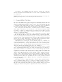
Fig. 4 shows the hierarchical interface model of a simple data logger component, Recorder. By receiving a start input signal, the component enters into a
loop of data acquisition (getData, dataRdy) using for example a sensor peripheral and data storage (saveData). The module must be prepared to receive a
stop signal and leave the loop at any moment.
The flat interface model of the same component is given in Fig. 5. Even for
this simple component, the benefits of the hierarchical model are noticeable, not
only because we have spared two “arrows” in the model, but because it depicts
the essence of the stop signal and preserves visual clarity. If the logic in the
recording loop needs refinement, the hierarchy ensures that the stop signal will
be handled in the new states, as well, which is not true in the flat scenario.
getData!
start?
dataRdy?
dataRdy?
getData!
start?
s11
s0
s12
stop!
saveData!
s13
s1
s0
s2
s3
saveData!
s1
stop!
start
stop
getData
dataRdy
saveData
Fig. 4. Hierarchical interface model of
Recorder.
start
stop
Fig. 5. Flat
Recorder.
getData
dataRdy
interface
saveData
model
of
The original Interface Automata language is a superb formalism for specifying interfaces in event driven systems where each component has its own thread
of control and the components engage one another asynchronously via events.
However, the concepts of interface automata cannot be mapped to typical embedded applications easily, where the software components are linked together
and communicate via function calls. Since our primary goal was to provide interface models for TinyOS components, we had to address the following issues:
– What constitutes an action in these applications? Is it only the function call
that conveys information, or its return also?
– Interface Automata make decisions based purely on the received actions,
unlike in procedural systems where actions are accompanied by quantitative
parameters that have strong influence on the control flow.
– In monolithic embedded applications the assumptions of parallel execution
and asynchronous message passing no longer hold. Implicit constraints restrict the execution of an automaton that are inherent in sequential execution.
To address the first problem, we have chosen the function calls as the sole
representation of actions in the interface model. Our decision was influenced by a
feature provided by the nesC compiler, which allows to “fan out” a function call
to multiple functions, that itself raises the question of what the return value of
a function means. The second question may be resolved by introducing multiple
actions for a given function, however, an extension of the interface language with
action parameters is an area of further study.
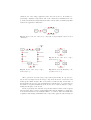
The last problem has driven us to introduce another modification to the
original language. Fig. 7 depicts the interface automata of a common embedded
component that provides access to the display LEDs of the hardware. Our driver
is fairly simple: it allows to turn off or on both of its supervised LEDs (red and
green). Using the original interface automata language and the pessimistic compatibility rules, the interface becomes incomprehensible, since it needs to handle
incoming requests disregarding its current state. In practice, this component
would turn on or off all of the LEDs by using a simple sequence of commands
in an atomic way. Therefore, we have introduced non-preemptable states, which
enable us to specify atomic action sequences as shown in Fig. 6. Upon entering
a non-preemptable state—designated by solid circles—multiple output actions
are allowed to be sent before entering a regular state again. Non-preemptable
states can be implemented in several ways: the most trivial approach is interrupt
masking or the use of mutexes. The nesC language and the TinyOS concurrency
model has similar constructs, which make a distinction between asynchronous
and synchronous code.
rOn!
On?
On?
gOn!
rOn!
gOn!
s1
s0
s1
On?
Off?
s0
s2
rOff!
Off?
On?
On
Off
redOn
redOff
greenOn
Off?
s5
Off?
rOff!
gOff!
greenOff
Fig. 6. Interface model of component
LEDs with non-preemptable states.
On
s3
On?
Off?
Off?
On?
On?
Off?
s4
On?
gOff!
Off
redOn
Off?
redOff
greenOn
greenOff
Fig. 7. Interface model of component
LEDs using the original automata language.
The hierarchical representation of interfaces can be transformed automatically to the traditional flat notation, thus the original rules of compatibility are
applicable to hierarchical models. The introduction of non-preemptable states,
however, needs a slight modification to these formulae. The formal definition of
compatibility in Hierarchical Interface Automata is given in the next section.
The definition of hierarchical interface automata follows.
Definition 2. A hierarchical interface automaton P consists of the following
elements:
– elements of regular interface automata as defined in Definition 1.
– HP , a set of hierarchical states, each of which is a subset of SP together with
a selected element, called the initial sub-state of the hierarchical state. Steps
originating from hierarchical states are implicitly defined for each contained
sub-state. Steps entering into hierarchical states are implicitly defined for the
contained initial sub-state.
– SPnp , a set of non-preemptable states, SPnp ⊆ SP . The automaton does not
accept input actions in non-preemptable states.
4.3
Visual Language Specification
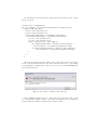
Temporal interface models complement the traditional interfaces of TinyOS components, thus integrating these automaton concepts into the existing Gratis language is the natural choice. The metamodel of the hierarchical interface automata language is shown in Fig. 8. The module, interface and FunctionBase
meta objects are joint concepts in the original Gratis and the automata language; they connect the type based and temporal models. The multi-aspect
capability of the modeling environment enables the separate visualization of the
alternative representations of component interfaces. The apparent symmetry in
the metamodel stems from the fact that the language can capture the temporal
models of both components and interfaces.
TinyOS interfaces and modules can contain states (mState and iState) that
can be nested, and actions (actionRef and FunctionBase, that can be used to
connect states. Special boolean attributes of the state object may designate it
as an initial (IsInit) or non-preemptable (IsPreemptable) state.
Fig. 8. The metamodel of the Hierarchical Interface Automata language
4.4
Composition Rules
We consider two hierarchical interface automata composable if there is no conflict
between their actions, thus they only possess common actions which move the
product automaton along shared steps.
Definition 3. Two interface automata P and Q are composable if
H
O
O
I
I
AH
P ∩ AQ = ∅, AQ ∩ AP = ∅, AP ∩ AQ = ∅, and AP ∩ AQ = ∅.
As we have seen previously, the composite automaton consists of the product
of the original (leaf) states and the conjunction of actions reduced by the set of
joint actions. Composite steps are defined as for normal interface automata; the
only difference is in the special treatment of intermediate states: input actions
in the original automata are not accepted while the other component resides in
a non-preemptable state.
Definition 4. If two interface automata P and Q are composable, their product
P × Q is defined by
SP ×Q = SP × SQ ,
np
},
SPnp×Q = { (s, t) ∈ SP ×Q | s ∈ SPnp ∨ t ∈ SQ
init
init
SPinit
× SQ
,
×Q = SP
AIP ×Q = AIP ∪ AIQ \ Ashared
P ×Q ,
O
O
shared
AO
P ×Q = AP ∪ AQ \ AP ×Q ,
H
H
shared
AH
P ×Q = AP ∪ AQ ∪ AP ×Q ,
np
TP ×Q = { ((s, t), a, (s0 , t)) | (s, a, s0 ) ∈ TP ∧ a ∈
/ Ashared
P ×Q ∧ t ∈ (SQ \ SQ ) }
np
∪ { ((s, t), a, (s, t0 )) | (t, a, t0 ) ∈ TQ ∧ a ∈
/ Ashared
P ×Q ∧ s ∈ (SP \ SP ) }
∪ { ((s, t), a, (s0 , t0 )) | (s, a, s0 ) ∈ TP ∧ (t, a, t0 ) ∈ TQ ∧ a ∈ Ashared
P ×Q },
where Ashared
P ×Q = AP ∩ AQ .
The definition of illegal states is the key step towards understanding compatibility between components. Compared to the informal description of illegal
states given earlier, we had to alter the definition because non-preemptable states
are excluded from the analysis.
Definition 5. The set of illegal states in the product of hierarchical interface
automata P and Q are defined by
n
SPillegal
(s, t) | (s, t) ∈ SP ×Q ∧ ∃a ∈ AP ∩ AQ
×Q =
³¡
¢
np
a ∈ AO
/ SQ
∧ ∃(s, a, s0 ) ∈ TP ∧ @(t, a, t0 ) ∈ TQ
P ∧t∈
¡
¢´ o
∨ a ∈ AO
/ SPnp ∧ ∃(t, a, t0 ) ∈ TQ ∧ @(s, a, s0 ) ∈ TP
.
Q∧s∈
According to the pessimistic approach one has to traverse the composite
interface automaton from its initial state to decide on the compatibility between
the components.
Definition 6. We consider two hierarchical interface automata P and Q compatible if no illegal states can be reached from the initial states.
5
Compatibility Checking
The previous definitions for composability and compatibility may be enforced
by custom algorithms using graph- or game theoretical [1] foundations. The
Generic Modeling Environment provides access to the model database through
a documented API, which makes it possible to implement these algorithms in
the form of model interpreters using conventional procedural languages.
The development and maintenance of such interpreters are time consuming
tasks, slight modifications to the metamodel of the automata language might
necessiate a complete reconstruction at the interpreter level, while—in most
cases—only common sense assures consistency between the formal definitions
and the procedural algorithms.
For the reasons above we started to explore alternative approaches, which
reduce the time and effort needed to map formal rules into executable algorithms.
One of our promising methods utilizes Prolog [6] to automatically generate logical
predicates based on the visual interface specifications. The generated statements
and the logic program counterparts of our formal rules are then merged in the
prolog interpreter, where compatibility checks are performed.
Althought the procedural part of model checking reduced to a simple code
generator by using logic programs, it still exhibits redundancy, since the concepts
of the metamodel have to be reproduced in the source code of the interpreter.
With the use of the constraint language that is natively supported by the modeling environment, this remaining part can be also eliminited.
The Object Constraint Language (OCL) [8] is a formal extension of UML
based on mathematical first-order logic. OCL expressions are used to fully specify the static semantics of a domain, i.e. the set of rules that specify the wellformedness of domain models, which cannot be fully described by UML class
diagrams. The OCL is a multi-sorted predicate language. The domains are the
classes of the UML metamodel, and the elements of these domains are the instances of these classes. Relations between the domains are UML associations.
Typical logical connectives (not, and, or, implies), the universal (forAll) and
existential (exists) first-order quatifiers and various other predefined relations
(=, <>, in, etc.) and operators (parent, any, etc.) are avaliable, making OCL a
rich, typed language.
The main objective of using OCL was to describe static semantics and intricate constraints, which cannot be captured by visual notation. However, the
expressiveness of the language makes it possible to analyse dynamic behavior—
like discovering reachable states. Moreover, the declarative nature of the OCL
language provides an ideal ground to implement and execute formal rules.
To demonstrate the effectiveness of this approach the OCL version of Definition 3 is given:
context meta::configuration
inv: let modules = self.referenceParts(meta::module_ref) in
comps->forAll(mr1,mr2 |
let m1 = mr1.refersTo() in
let m2 = mr2.refersTo() in
m1.referenceParts(meta::actionRef)->forAll(ar1 |
m2.referenceParts(meta::actionRef)->forAll(ar2 |
let f1 = ar1.refersTo() in
let f2 = ar2.refersTo() in
((m1 <> m2) and (f1 = f2)) implies
m1.referenceParts(meta::interface_ref)->any(ir1 |
ir1.refersTo() = f1.parent()).ByInterfaceType
<> m2.referenceParts(meta::interface_ref)->any(ir2 |
ir2.refersTo() = f2.parent()).ByInterfaceType
)
)
)
)
After incorporating the OCL variant of the composition rule into the metamodel of the hierarchical interface automata domain violations of composability
in each TinyOS configuration models are detected by the ConstraintManager,
as it is shown in Fig. 9.
Fig. 9. Composability constraint violation message
The remaining definitions can be easily mapped as well; the entire toolset
for compatibility checking consists of few OCL constraints, that are tightly integrated with the definition (metamodel) of their domain.
6
Model Verification
Interface automata capture only the surface of software components, because
these descriptions are not sufficient for automatic code synthesis or simulation.
They can be constructed even after the implementation phase of the component,
as it is the case when dealing with existing TinyOS modules. Therefore, some
kind of automatic verification is needed assuring that consistency between the
formal model and the implementation is maintained.
Model verification with existing source code—especially if the code was not
created with a model centric approach—is a cumbersome if not impossible task.
Analyzing sources written in traditional procedural languages like C implies
heuristic methods. Their dependency on the target implementation language
makes the effort questionable.
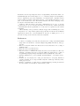
We have chosen a different approach, which“interrogates” the existing modules and instead of trying to understand the source files, it generates additional
code based on the interface models. The generated software behaves like a wrapper around the component to be tested, it generates each signal which is accepted
by the component and it is prepared to receive all of the events coming from
the module. The wrapper code reckons with the specified order of events, it
executes the interface automata by transmitting actions in proper states and
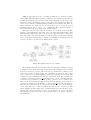
catching unexpected incoming messages. Fig. 10 demonstrates the model verification process. This simple, yet powerful approach treats existing modules as
black box components, therefore, it can handle even the most obfuscated source
code.
a?
b?
s0
s1
c?
s2
s3
d!
s5
d
e
f
g
b
f!
s4
a
g?
e!
c
wrapper generator
Component
s7
s6
model
Tester
Fig. 10. The model verification process
The prototype implementation of our black box testing approach targets the
TinyOS platform. It requires manual intervention in those interface states where
alternative output steps can be made by the tester, though automatic exhaustive
testing could be easily achieved, as well.
7
Case Study
To demonstrate the expressiveness of the hierarchical interface automata language and the benefits of automatic composition checks, we further refine the
visual model of the Surge application introduced in section 3. In addition to
presenting compatible temporal models of the central and communication components, an alternative implementation will be shown where a small design flaw
renders the application unreliable.
Fig. 11. Top level model of the Surge component. Non-preemptable states are used
extensively.
Fig. 13. Model of the P hoto component’s service loop.
Fig. 12. Model of the Surge component’s busy loop.
Fig. 14. Model of the M ultiHop component’s service loop.
The top level model of the Surge component is given in Fig. 11. Upon receiving an Std.start input action the Surge component enters the started state and
starts up the Timer module. The started state is refined in Fig. 12. Because of
the hierarchy, the Std.stop action is handled in each sub-state of started, thereby
the number of explicit transitions in the model can be reduced without compromising the integrity of the model.
In the started state the automaton repeatedly waits for timer events, requests
data from the A/D converter, sends samples through the multi-hop routing network and then waits for the transmit buffer to be cleared. After successful data
acquisition and message transmission the component toggles the yellow and green
LEDs respectively. Note how non-preemptive states, denoted by filled circles,
prevent the model from growing complicated and unreadable.
The temporal models of the multi-hop routing and ADC components are
shown in Fig. 14 and Fig. 13. Albeit only the inner service loops are shown, the
models present the restriction of both components clearly: they are not prepared
to process multiple requests simultaneously.
Fig. 15. Model of the faulty Surge component’s busy loop.
The Surge component overcomes this limitation by waiting for ADC.dataReady
and Send.sendDone events before advancing to subsequent states and completing
the iteration, thereby facilitating trivial flow control in the system. In the case
of the multi-hop communication, it even detects congestion—new Timer.fired
event arrives while the component is still waiting for the previous message to be
sent—and signals this situation by turning on the red LED.
The erroneous implementation of the Surge component shown in Fig. 15 differs exactly in this regard. The automaton depicts a typical mistake; it essentially
discards an event coming from the multi-hop component. After its first iteration
the Surge component may acquire a new sample from the A/D module, while
the communication component is still in its sending state, where the Send.send
event is not accepted. This application is unreliable, its operation depends on
the timing properties of the data acquisition, periodic timer and task scheduling. This error—a reachable illegal state—is caught by automatic verification.
In contrast, manual debugging of similar problems may easily become a time
consuming task.
8
Conclusions
The proposed model-based approach to the component-based development of
networked embedded systems places a special emphasis on interface specification. The presented formalism captures both the temporal and the type aspects
of interfaces. It also facilitates the composition and verification of components
and component assemblies. The experience gained by using the prototype modeling environment and the integrated verification tools can help in refining and
extending these concepts and techniques in the future.
The Surge example clearly demonstrates the benefits of the proposed extensions to the interface automata language, that is the introduction of state
hierarchies and non-preemptable states. Compatibility checks with OCL constraintsalthough unconventionalprove to be extremely simple and straightforward to implement, given the availability of a built-in OCL constraint checker
in the baseline modeling environment. In fact, composability rules have become
part of the metamodels of the hierarchical interface automaton language; they
specify the well-formedness of the models.
Function call-based inter-component communication is a topic of ongoing
research, since it does not fit the automata model perfectly: return values and
constraints inherent in sequential flow of control are not captured by the current
formalism.
The scalability of the presented verification approach is a limiting factor; the
composition of n components requires O(n2 ) pair-wise checks. For most TinyOS
applications, this is not a serious limitation; however, it might prove to be a
problem for large scale networked embedded systems.
References
1. de Alfaro, L., Henzinger, T.A.: Interface Automata. Proceedings of the Ninth Annual
Symposium on Foundations of Software Engineering (FSE). ACM Press, 2001, pp.
109-120
2. Hill, J. at al: System Architecture Directions for Networked Sensors. Proceedings of
ASPLOS, 2000
3. Reference removed for blind review
4. Reference removed for blind review
5. Gay, D., Levis, P., von Behren, R., Welsh, M., Brewer, E. and Culler, D.: The nesC
Language: A Holistic Approach to Networked Embedded Systems. Proceedings of
Programming Language Design and Implementation (PLDI) 2003, June 2003
6. SICStus: SICStus Prolog User’s Manual. Swedish Institute of Computer Science,
Sweden
7. Garland, S.J. and Lynch, N.A.: Using I/O automata for developing distributed
systems. Foundations of Component-Based Systems. Cambridge University Press,
2000, pages 285-312
8. Warmer, J. and Kleppe, A.: The Object Constraint Language: Getting Your Models
Ready for MDA, Second Edition. Addison-Wesley, 2003