1
visual model of the Surge application introduced in section 3. In addition to
presenting compatible temporal models of the central and communication components, an alternative implementation will be shown where a small design flaw
renders the application unreliable.
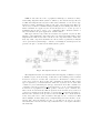
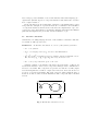
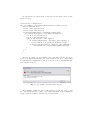
Fig. 11. Top level model of the Surge component. Non-preemptable states are used
extensively.
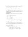
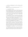
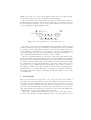
Fig. 13. Model of the P hoto component’s service loop.
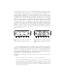
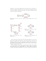
Fig. 12. Model of the Surge component’s busy loop.
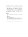
Fig. 14. Model of the M ultiHop component’s service loop.
The top level model of the Surge component is given in Fig. 11. Upon receiving an Std.start input action the Surge component enters the started state and
starts up the Timer module. The started state is refined in Fig. 12. Because of
the hierarchy, the Std.stop action is handled in each sub-state of started, thereby
the number of explicit transitions in the model can be reduced without compromising the integrity of the model.
In the started state the automaton repeatedly waits for timer events, requests
data from the A/D converter, sends samples through the multi-hop routing network and then waits for the transmit buffer to be cleared. After successful data
acquisition and message transmission the component toggles the yellow and green