1
1788HP-EN2PA - User Manual Rev 5.06
MODULE OPERATION & INSTALLATION
CHAPTER 2
The 1788HP-EN2PA module is designed to operate within the Allen-Bradley Logix
controller system using CIP Ethernet. All power required for the module’s operation must
be derived from an external 24V power supply. Please refer to electrical specifications for
current consumption.
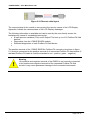
LCD Display
PA Bus
24V Power supply
RJ45 Ethernet
Figure 2.1: 1788HP-EN2PA Layout
PABUS:
24V PWR:
RJ45:
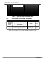
Connector Pin 1 -> PA “+” terminal, Connector Pin 3 -> PA – terminal. Pin 4
is used for the cable shield.
Connector Pin 1 -> “+” terminal, Connector Pin 2 -> “-“ terminal
Connector Pin 1 & 3 and Connector Pin 2 & 4 are twisted pairs as shown
below in figure 2.2.
.
Page 4 of 31