1
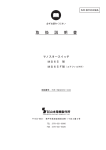
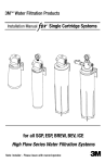
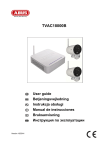
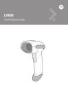
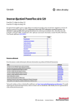
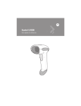
Product Information Český 注意 注意:若未阅读产品文档以及“ 其它资源” 小节中提及的有关安装、配置、 运行或维护设备的相关文档,请勿安装、配置、运行或维护本产品。请访问 http://www.rockwellautomation.com/literature 或联系您当地的销售办事处或 罗克韦尔自动化代表,以获取产品文档。 注意: 在您完整閱讀本產品相關文件及其他關於安裝、 配置、 操作或 維護設備等資料之前、 請勿安裝、 配置、 操作或維護此產品。您可到下列 網站下載所有產品相關文件 http://www.rockwellautomation.com/literature , 或聯繫洛克威爾自動化當地辦公室。 ВНИМАНИЕ: Не устанавливайте, не конфигурируйте, не запускайте в эксплуатацию и не поддерживайте работу продукта до прочтения технической документации по продукту и документации в разделе Дополнительные материалы для инсталлирования, конфигурирования, запуска в эксплуатацию и поддержки работы продукта. Чтобы ознакомиться с документацией по продукту, перейдите по ссылке http://www.rockwellautomation.com/literature или свяжитесь с локальным офисом продаж или представителем Rockwell Automation. UWAGA: Nie instaluj i nie uruchamiaj tego urządzenia dopóki nie zapoznasz się z instrukcją użytkownika produktu. Aby uzyskać dokumentację produktu przejdź do strony internetowej http://www.rockwellautomation.com/literature lub skontaktuj się z lokalnym biurem sprzedaży lub przedstawicielstwem firmy Rockwell Automation. UPOZORŇENÍ: Neprovádějte instalaci, konfiguraci, provoz ani údržbu, pokud jste dosud nepřečetli dokumentaci k produktu a dokumenty obsažené v sekci Doplňující informace pro instalaci, konfiguraci, provoz a údržbu. Tuto dokumentaci můžete získat na http://www.rockwellautomation.com/literature nebo od obchodního zástupce společnosti Rockwell Automation. These documents contain additional information concerning the installation, programming, and application of the AC drive. English The user manual is available in multiple languages at http://www.rockwellautomation.com/literature. Select publication language and type “520-UM001“ in the search field. Deutsch Das benutzer handbuch steht in mehreren Sprachen unter http://www.rockwellautomation.com/literature zur Verfügung. Wählen Sie Ihre Sprache aus, und geben Sie „520-UM001“ in das Suchfeld ein. Français La manuel utilisateur est disponible dans différentes langues à l’adresse suivante: http://www.rockwellautomation.com/literature. Sélectionner la langue puis taper « 520-UM001 » dans le champ de recherche. Italiano La manuale d'uso è disponibile in varie lingue sul sito http://www.rockwellautomation.com/literature. Selezionare la lingua desiderata e digitare “520-UM001“ nel campo di ricerca. Español Puede encontrar el manual del usuario en varios idiomas en http://www.rockwellautomation.com/literature. Selecione el idioma de publicación y escriba “520-UM001“ en el campo de búsqueda. Português O manual de usuário está disponível em várias línguas em http://www.rockwellautomation.com/literature. Seleccione a língua de publicação e entre com “520-UM001“ no espaço de busca. 한국의 Frame Screw Size Screw Torque A B C D E M5 (#10...24) M5 (#10...24) M5 (#10...24) M5 (#10...24) M8 (5/16 in.) 1.56...1.96 Nm (14...17 lb-in.) 1.56...1.96 Nm (14...17 lb-in.) 1.56...1.96 Nm (14...17 lb-in.) 2.45...2.94 Nm (22...26 lb-in.) 6.0...7.4 Nm (53...65 lb-in.) 中文 (简体) ᣣᧄ Русский "520-UM001" . 从以下网页可以获得用户手册的多种语言的版本: http://www.rockwellautomation.com/literature 。 请选择出版物的语言, 并在搜索栏输入“520-UM001” 印。 ࡙ࠩ࠭ࡑ࠾ࡘࠕ࡞ߩᄙ⸒⺆ ߪ9GDࠨࠗ࠻ http://www.rockwellautomation.com/literatureߡߦޓᚻߢ߈ߔޕ ⸒⺆ࠍㆬᛯߒޔ ᬌ⚝ࡈࠖ࡞࠼ߦޟ7/ޕߐߛߊߡߒࡊࠗ࠲ߣޠ Руководство пользователя на других языках можно найти по адресу http://www.rockwellautomation.com/literature. Выберите язык и введите в окно поиска «520-UM001». 中文 以下網頁提供使用手册的多國語言版本: (繁體) http://www.rockwellautomation.com/literature 。請選擇出版語言,並於搜尋欄鍵入 Ā80ā 即可。 Publication 520-PC001B-EN-P - June 2013 Ship Weight 140 (5.51) 168 (6.61) 207 (8.15) 247 (9.72) 280 (11.02) 1.1 (2.4) 1.6 (3.5) 2.3 (5.0) 3.9 (8.6) 12.9 (28.4) EMC Filters See the PowerFlex 525 User Manual for instructions on complying with the EMC Directive. Dimensions are in mm and (in.). D B F A E • Protect the cooling fan by avoiding dust or metallic particles. • Do not expose to a corrosive atmosphere. • Protect from moisture and direct sunlight. G Minimum Mounting Clearances Vertical mounting is shown. If mounting horizontally, apply same clearances plus 50 mm (2.0 in.) clearance from the top and bottom of enclosure to allow for proper airflow. Vertical Vertical, Zero Stacking No clearance required between drives. I 50 mm (2.0 in.) 25 mm (1.0 in.) Esc Sel Esc Sel Sel I F C D E F G H I A 55.0 (2.17) 70.0 (2.76) 70.0 (2.76) 80.0 (3.15) 80.0 (3.15) 72.0 (2.83) 87.0 (3.43) 109.0 (4.29) 130.0 (5.12) 155.0 (6.10) 234.0 (9.21) 270.0 (10.63) 275.0 (10.83) 310.0 (12.20) 390.0 (15.35) 30.0 (1.18) 35.0 (1.38) 37.0 (1.46) 33.0 (1.30) 32.0 (1.26) 223.0 (8.78) 258.0 (10.16) 263.0 (10.35) 298.0 (11.73) 375.0 (14.76) 54.0 (2.13) 58.0 (2.28) 76.0 (2.99) 90.0 (3.54) 110.0 (4.33) 20.0 (0.79) 25.0 (0.98) 25.0 (0.98) 33.0 (1.30) 33.0 (1.30) 23.0 (0.91) 24.0 (0.94) 28.0 (1.10) 28.0 (1.10) 28.0 (1.10) 5.5 (0.22) 5.5 (0.22) 5.5 (0.22) 5.5 (0.22) 5.5 (0.22) B D Esc H B E Esc C E A C 50 mm (2.0 in.) Sel Output Ratings Input Ratings Branch Circuit Protection Normal Heavy Duty Duty Voltage Range HP kW HP kW 50 mm (1) (2.0 in.) 50 mm (1) (2.0 in.) Esc Esc Sel Sel Esc Esc Sel 140M Motor Protectors (2) (3) IP20/Open Type Watts Loss Catalog No.(1) 50 mm (2.0 in.) Contactors 50 mm (2.0 in.) Fuse Ratings Min./Max. Fuses and Circuit Breakers 100...120V AC (-15%, +10%) – 1-Phase Input, 0...230V 3-Phase Output 25B-V2P5N104 0.5 0.4 0.5 0.4 2.5 85...132 1.3 9.6 15/20 140M-C2E-C10 100-C12 27.0 25B-V4P8N104 1.0 0.75 1.0 0.75 4.8 85...132 2.5 19.2 25/40 140M-D8E-C20 100-C23 53.0 25B-V6P0N104 1.5 1.1 1.5 1.1 6.0 85...132 3.2 24.0 30/50 140M-F8E-C25 100-C23 67.0 Sel 200...240V AC (-15%, +10%) – 1-Phase Input, 0...230V 3-Phase Output 25 mm (1.0 in.) 50 mm (2.0 in.) Vertical with Fan Kit (1) (2) 25B-A2P5N104 25B-A4P8N104 25B-A8P0N104 25B-A011N104 (2) 50 mm (2.0 in.) Vertical, Zero Stacking with Fan Kit No clearance required between drives. Enclosure Rating(1) Ambient Temperature Min. Vertical IP 20/Open Type IP 30/NEMA 1/UL Type 1 IP 20/Open Type IP 30/NEMA 1/UL Type 1 IP 20/Open Type Vertical, Zero Stacking Horizontal with Control Module Fan Kit(4)(5) Horizontal, Zero Stacking with IP 20/Open Type Control Module Fan Kit(4)(5) (1) Max. Max. Max. with (No Derate) (Derate)(2) Fan Kit (Derate)(3)(5) 50 °C (122 °F) 45 °C (113 °F) 45 °C (113 °F) 40 °C (104 °F) -20 °C (-4 °F) 50 °C (122 °F) 45 °C (113 °F) 60 °C (140 °F) 55 °C (131 °F) 55 °C (131 °F) 50 °C (122 °F) – 70 °C (158 °F) – 65 °C (149 °F) – 70 °C (158 °F) – 65 °C (149 °F) IP 30/NEMA 1/UL Type 1 rating requires installation of the PowerFlex 520-Series IP 30/NEMA 1/UL Type 1 option kit, catalog number 25-JBAx. For catalogs 25B-D1P4N104 and 25B-E0P9N104, the temperature listed under the Max. (Derate) column is reduced by 5 °C (9 °F) for all mounting methods. For catalogs 25B-D1P4N104 and 25B-E0P9N104, the temperature listed under the Max. with Fan Kit (Derate) column is reduced by 10 °C (18 °F) for vertical and vertical with zero stacking mounting methods only. Catalogs 25B-D1P4N104 and 25B-E0P9N104 cannot be mounted using either of the horizontal mounting methods. Requires installation of the PowerFlex 520-Series Control Module Fan Kit, catalog number 25-FANx-70C. (2) (3) (4) (5) Drive Dimensions Ratings are in kW and (HP). Frame 1-Phase 1-Phase 1-Phase 3-Phase 3-Phase 3-Phase 3-Phase 100...120V 200...240V 200...240V 200...240V 380...480V 380...480V 525...600V w/ Filter w/ Filter A C 0.4 (0.5) 0.75...1.1 (1.0...1.5) – 0.4...0.75 (0.5...1.0) 1.5...2.2 (2.0...3.0) – 0.4...0.75 (0.5...1.0) 1.5...2.2 (2.0...3.0) – D – – – E – – – B 0.4...2.2 (0.5...3.0) 3.7 (5.0) 5.5 (7.5) 7.5 (10.0) 11.0...15.0 (15.0...20.0) 0.4...2.2 (0.5...3.0) 4.0 (5.0) 5.5...7.5 (7.5...10.0) 11.0...15.0 (15.0...20.0) – 0.4...2.2 (0.5...3.0) 4.0 (5.0) 5.5...7.5 (7.5...10.0) 11.0...15.0 (15.0...20.0) 18.5...22.0 (25.0...30.0) IP20/Open Type Dimensions are in mm and (in.). Weights are in kg and (lb). C A D Esc B Sel 25B-A2P5N114 25B-A4P8N114 25B-A8P0N114 25B-A011N114 0.4...2.2 (0.5...3.0) 3.70 (5.00) 5.5...7.5 (7.5...10.0) 11.0...15.0 (15.0...20.0) 18.5...22.0 (25.0...30.0) 25B-B2P5N104 25B-B5P0N104 25B-B8P0N104 25B-B011N104 25B-B017N104 25B-B024N104 25B-B032N104 25B-B048N104 25B-B062N104 0.5 1.0 2.0 3.0 0.4 0.75 1.5 2.2 2.5 4.8 8.0 11.0 170...264 170...264 170...264 170...264 1.7 2.8 4.8 6.0 6.5 10.7 18.0 22.9 10/15 15/25 25/40 30/50 140M-C2E-C10 140M-C2E-C16 140M-F8E-C25 140M-F8E-C25 100-C09 100-C12 100-C23 100-C37 29.0 50.0 81.0 111.0 0.5 1.0 2.0 3.0 0.4 0.75 1.5 2.2 0.5 1.0 2.0 3.0 0.4 0.75 1.5 2.2 2.5 4.8 8.0 11.0 170...264 170...264 170...264 170...264 1.7 2.8 4.8 6.0 6.5 10.7 18.0 22.9 10/15 15/25 25/40 30/50 140M-C2E-C10 140M-C2E-C16 140M-F8E-C25 140M-F8E-C25 100-C09 100-C12 100-C23 100-C37 29.0 53.0 84.0 116.0 0.5 1.0 2.0 3.0 5.0 7.5 10.0 15.0 20.0 0.4 0.75 1.5 2.2 3.7 5.5 7.5 11.0 15.0 0.5 1.0 2.0 3.0 5.0 7.5 10.0 15.0 15.0 0.4 0.75 1.5 2.2 3.7 5.5 7.5 11.0 11.0 2.5 5.0 8.0 11.0 17.5 24.0 32.2 48.3 62.1 170...264 170...264 170...264 170...264 170...264 170...264 170...264 170...264 170...264 1.2 2.7 4.3 6.3 9.6 12.2 15.9 20.1 25.6 2.7 5.8 9.5 13.8 21.1 26.1 34.8 44.0 56.0 6/6 10/15 15/20 20/30 30/45 35/60 45/70 60/90 70/125 140M-C2E-B40 140M-C2E-B63 140M-C2E-C10 140M-C2E-C16 140M-F8E-C25 140M-F8E-C32 140M-F8E-C45 – – 100-C07 100-C09 100-C12 100-C23 100-C23 100-C37 100-C43 100-C60 100-C72 29.0 50.0 79.0 107.0 148.0 259.0 323.0 584.0 708.0 100-C07 100-C07 100-C09 100-C09 100-C23 100-C23 100-C23 100-C37 100-C43 27.0 37.0 80.0 86.0 129.0 170.0 221.0 303.0 387.0 380...480V AC (-15%, +10%) – 3-Phase Input, 0...460V 3-Phase Output 25B-D1P4N104 25B-D2P3N104 25B-D4P0N104 25B-D6P0N104 25B-D010N104 25B-D013N104 25B-D017N104 25B-D024N104 25B-D030N104 0.5 1.0 2.0 3.0 5.0 7.5 10.0 15.0 20.0 0.4 0.75 1.5 2.2 4.0 5.5 7.5 11.0 15.0 0.5 1.0 2.0 3.0 5.0 7.5 10.0 15.0 15.0 0.4 0.75 1.5 2.2 4.0 5.5 7.5 11.0 11.0 1.4 2.3 4.0 6.0 10.5 13.0 17.0 24.0 30.0 323...528 323...528 323...528 323...528 323...528 323...528 323...528 323...528 323...528 1.7 2.9 5.2 6.9 12.6 14.1 16.8 24.1 30.2 1.9 3.2 5.7 7.5 13.8 15.4 18.4 26.4 33.0 3/6 6/10 10/15 10/15 20/30 20/35 25/40 35/60 45/70 140M-C2E-B25 140M-C2E-B40 140M-C2E-B63 140M-C2E-C10 140M-C2E-C16 140M-D8E-C20 140M-D8E-C20 – – 380...480V AC (-15%, +10%) – 3-Phase Input with EMC Filter, 0...460V 3-Phase Output 25B-D1P4N114 25B-D2P3N114 25B-D4P0N114 25B-D6P0N114 25B-D010N114 25B-D013N114 25B-D017N114 25B-D024N114 25B-D030N114 0.5 1.0 2.0 3.0 5.0 7.5 10.0 15.0 20.0 0.4 0.75 1.5 2.2 4.0 5.5 7.5 11.0 15.0 0.5 1.0 2.0 3.0 5.0 7.5 10.0 15.0 15.0 0.4 0.75 1.5 2.2 4.0 5.5 7.5 11.0 11.0 1.4 2.3 4.0 6.0 10.5 13.0 17.0 24.0 30.0 323...528 323...528 323...528 323...528 323...528 323...528 323...528 323...528 323...528 1.7 2.9 5.2 6.9 12.6 14.1 16.8 24.1 30.2 1.9 3.2 5.7 7.5 13.8 15.4 18.4 26.4 33.0 3/6 6/10 10/15 10/15 20/30 20/35 25/40 35/60 45/70 140M-C2E-B25 140M-C2E-B40 140M-C2E-B63 140M-C2E-C10 140M-C2E-C16 140M-D8E-C20 140M-D8E-C20 – – 100-C07 100-C07 100-C09 100-C09 100-C23 100-C23 100-C23 100-C37 100-C43 27.0 37.0 81.0 88.0 133.0 175.0 230.0 313.0 402.0 25B-D037N114 25.0 18.5 20.0 15.0 37.0 323...528 30.8 33.7 45/70 140M-F8E-C45 100-C43 602.0 25B-D043N114 30.0 22.0 25.0 18.5 43.0 323...528 35.6 38.9 50/80 140M-F8E-C45 100-C60 697.0 525...600V AC (-15%, +10%) – 3-Phase Input, 0...575V 3-Phase Output 25B-E0P9N104 25B-E1P7N104 25B-E3P0N104 25B-E4P2N104 25B-E6P6N104 25B-E9P9N104 25B-E012N104 25B-E019N104 25B-E022N104 25B-E027N104 25B-E032N104 (1) (2) (3) E 0.4 0.75 1.5 2.2 200...240V AC (-15%, +10%) – 3-Phase Input, 0...230V 3-Phase Output Ambient Operating Temperatures Mounting 0.5 1.0 2.0 3.0 200...240V AC (-15%, +10%) – 1-Phase Input with EMC Filter, 0...230V 3-Phase Output For Frame E with Fan Kit only, clearance of 95 mm (3.7 in.) is required. For Frame E with Fan Kit only, clearance of 12 mm (0.5 in.) is required. ㇠㟝㣄 ⬘⎨㛰http://www.rockwellautomation.com/literature . E 57.5 (2.26) 72.5 (2.85) 90.5 (3.56) 116 (4.57) 160 (6.30) • Mount the drive upright on a flat, vertical and level surface. PowerFlex 525 Frames Additional Resources D 172 (6.77) 172 (6.77) 184 (7.24) 212 (8.35) 279 (10.98) Mounting Considerations ᵈᗧ㧦 ᵈᗧ㧦ຠߩ⾗ᢱ߅ࠃ߮ㅊട⾗ᢱߦ⸥タߩⵝ⟎ߩขઃߌޔ᭴ᚑޔᠲޔ ߹ߚߪߦ㑐ߔࠆ⾗ᢱࠍ߅⺒ߺߦߥࠆ߹ߢߪߩߎޔຠߩขઃߌޔ ᭴ᚑޔᠲߪߚ߹ޔࠍⴕߥࠊߥߢߊߛߐޕຠߩ⾗ᢱࠍ ᚻߔࠆߦߪ ޔ9GDࠨࠗ࠻㧦http://www.rockwellautomation.com/literature ߦ ࠕࠢࠬߔࠆ߆ߩࡦ࡚ࠪࡔ࠻ࠝ࡞ࠚ࠙ࠢ࠶ࡠߪߚ߹ޔ༡ᬺ߹ߚߪ ⽼ᄁઍℂᐫ߹ߢߏㅪ⛊ߊߛߐޕ 주의사항 : 제품 매뉴얼 혹은설치 , 구성 , 가동 , 유지와 관련된 추가 지침서를 완전히 숙지하기 전까지 본 제품을 설치 혹은 가동하 지 마십시오 . 본 제품과 관련된 매뉴얼 혹은 문서를 원하시면 사이트 http://www.rockwellautomation.com/literature 를 방문 해주시거나 해당 지역의 로크웰 오토메이션대리점으 로 문의하십시오 . C 152 (5.98) 180 (7.09) 220 (8.66) 260 (10.24) 300 (11.81) Amps ATTENTION: Do not install, configure, operate or maintain this product until you have read the product documentation and the documents in the Additional Resources section for installing, configuring, operating or maintaining equipment. To get the product documentation go to http://www.rockwellautomation.com/literature or contact your local sales office or Rockwell Automation representative. ATTENTION: Ne pas installer, configurer, exploiter ou maintenir ce produit tant que vous n’avez pas lu sa documentation et les documents de la rubrique Documents connexes pour l’installation, la configuration, l’exploitation et la maintenance de l’équipement. Pour obtenir de la documentation, rendez-vous sur le site http://www.rockwellautomation.com/literature ou contactez votre agence commerciale Rockwell Automation locale ou son représentant. ACHTUNG: Für die Installation, Konfiguration, den Betrieb und die Wartung dieses Produkt lesen Sie sich bitte zunächst die Produktdokumentation sowie die Dokumente im Abschnitt “Weitere Informationen” durch. Die entsprechende Produktdokumentation finden Sie unter http://www.rockwellautomation.com/literature oder kontaktieren Sie Ihr lokales Vertriebsbüro bzw. einen Rockwell Automation-Mitarbeiter. ATENCIÓN: No instale, configure, opere ni mantenga este producto hasta que haya leído la documentación del producto y los documentos en la sección Recursos adicionales para la instalación, configuración, operación o mantenimiento de equipo. Para conseguir la documentación, diríjase a http://www.rockwellautomation.com/literature o póngase en contacto con su oficina regional de ventas o representante de Rockwell Automation. ATENÇÃO: Não instale, configure, opere ou mantenha este produto até que você leia a documentação do produto e os documentos na seção Recursos adicionais para a instalação, configuração, operação ou manutenção do equipamento. Para conseguir a documentação, visite http://www.rockwellautomation.com/literature ou entre em contato con seu escritório de vendas regional ou representante da Rockwell Automation. ATTENZIONE: Non installare, configurare, attivare o riparare questo prodotto senza avere prima letto la relativa documentazione nonchè i documenti indicati nella sezione Ulteriori Risore riguardanti l'installazione, la configurazione, l'attivazione o la riparazione dell'apparecchiatura. Per la documentazione sul prodotto visitare il sito http://www.rockwellautomation.com/literature o contattare l'ufficio vendite o il rappresentate Rockwell Automation di zona. B 72 (2.83) 87 (3.43) 109 (4.29) 130 (5.12) 185 (7.28) kVA ATTENTION: • Before installing, configuring, operating or maintaining this product, read this document and the documents listed in the Additional Resources section for installing, configuring, or operating equipment. Users should familiarize themselves with installation and wiring instructions in addition to requirements of all applicable codes, laws, and standards. • Installation, adjustments, putting into service, use, assembly, disassembly, and maintenance shall be carried out by suitably trained personnel in accordance with applicable code of practice. • If this equipment is used in a manner not specified by the manufacturer, the protection provided by the equipment may be impaired. • Solid state equipment has operational characteristics differing from those of electromechanical equipment. Safety Guidelines for the Application, Installation and Maintenance of Solid State Controls, publication SGI-1.1, available from your local Rockwell Automation sales office or online at http://www.rockwellautomation.com/literature describes some important differences between solid state equipment and hard-wired electromechanical devices. A A B C D E Amps Catalog Number 25B Frame Frame PowerFlex 525 Adjustable Frequency AC Drive Uživatelská příručka je k dispozici ve více jazykových verzích na adrese http://www.rockwellautomation.com/literature. Zvolte jazyk publikace a do vstupního pole pro vyhledávání zadejte „520-UM001“. Polski Instrukcja obsługi dostępna jest w wielu językach na stronie http://www.rockwellautomation.com/literature. Wybrać język publikacji, w polu wyszukiwania wpisać “520-UM001”. PowerFlex® 525 Adjustable Frequency AC Drive User Manual, publication 520-UM001: Detailed information on the parameters and specifications of the PowerFlex 525 drive. AC Drive Installation Considerations, publication DRIVES-IN003: Provides additional information needed to properly install PowerFlex AC drives. Wiring and Grounding Guidelines for Pulse Width Modulated (PWM) AC Drives, publication DRIVES-IN001: Provides basic information needed to properly wire and ground PWM AC drives. Industrial Automation Wiring and Grounding Guidelines, publication 1770-4.1: Provides general guidelines for installing a Rockwell Automation industrial system. 0.5 1.0 2.0 3.0 5.0 7.5 10.0 15.0 20.0 25.0 30.0 0.4 0.75 1.5 2.2 3.7 5.5 7.5 11.0 15.0 18.5 22.0 0.5 1.0 2.0 3.0 5.0 7.5 10.0 15.0 15.0 20.0 25.0 0.4 0.75 1.5 2.2 3.7 5.5 7.5 11.0 11.0 15.0 18.5 0.9 1.7 3.0 4.2 6.6 9.9 12.0 19.0 22.0 27.0 32.0 446...660 446...660 446...660 446...660 446...660 446...660 446...660 446...660 446...660 446...660 446...660 1.4 2.6 4.3 6.1 9.1 12.8 15.4 27.4 31.2 28.2 33.4 1.2 2.3 3.8 5.3 8.0 11.2 13.5 24.0 27.3 24.7 29.2 3/6 3/6 6/10 10/15 10/20 15/25 20/30 30/50 35/60 35/50 40/60 140M-C2E-B25 140M-C2E-B25 140M-C2E-B40 140M-C2E-B63 140M-C2E-C10 140M-C2E-C16 140M-C2E-C16 – – 140M-F8E-C32 140M-F8E-C32 100-C09 100-C09 100-C09 100-C09 100-C09 100-C16 100-C23 100-C30 100-C30 100-C30 100-C37 22.0 32.0 50.0 65.0 95.0 138.0 164.0 290.0 336.0 466.0 562.0 Normal and Heavy duty ratings are available for drives above 15 HP / 11 kW. The AIC ratings of the Bulletin 140M Motor Protector Circuit Breakers may vary. See Bulletin 140M Motor Protection Circuit Breakers Application Ratings. Manual Self-Protected (Type E) Combination Motor Controller, UL listed for 208 Wye or Delta, 240 Wye or Delta, 480Y/277 or 600Y/347. Not UL listed for use on 480V or 600V Delta/Delta, corner ground, or high-resistance ground systems. Integral Keypad Power Wiring No. Menu Location Rating/Type Standard (Option 1) 600V, 90 °C (194 °F) XHHW2/RHW-2 Anixter B209500-B209507, Belden 29501-29507, or equivalent Tray rated 600V, 90 °C (194 °F) RHH/RHW-2 Anixter OLF-7xxxxx or equivalent Tray rated 600V, 90 °C (194 °F) RHH/RHW-2 Anixter 7V-7xxxx-3G or equivalent Standard (Option 2) Class I & II; Division I & II ➊ ENET LINK EtherNet/IP Esc ➋ Terminal Blocks Programmable terminal functions. Sel Frame A, B, C and D Frame E L1/R L2/S L3/T T1/U T2/V T3/W Display/LED (Color) ➊ ENET (Steady) – Adapter connected to network and drive controlled via Ethernet. ENET (Flashing) – Adapter connected to network but drive not controlled via Ethernet. LINK (Steady) – Adapter connected to network but not transmitting data. LINK (Flashing) – Adapter connected to network and transmitting data. Fault Status (Red) L1/R L2/S L3/T T1/U T2/V T3/W DC- DC- DC+ BRBR+ BR- DC+ BR+ Description ➋ L1/R, L2/S, L3/T Input Line Voltage Connection T1/U, T2/V, T3/W Motor Phase = Connection Switch any two motor leads to change forward direction. Key Esc (1) Safety +24V Step 1.76...2.16 Nm (15.6...19.1 lb-in.) 1.76...2.16 Nm (15.6...19.1 lb-in.) 1.76...2.16 Nm (15.6...19.1 lb-in.) 1.76...2.16 Nm (15.6...19.1 lb-in.) 3.09...3.77 Nm (27.3...33.4 lb-in.) 1. Press the Up Arrow or Down Arrow to scroll to an AppView group (G1...G8). 01 02 03 SRC 04 05 06 07 08 +24V Relay 1 N.O. Relay 1 Common Relay 2 Common Relay 2 N.C. 11 R1 +10V 12 R2 13 R5 14 R6 15 0-10V 0/4-20 mA 16 17 18 30V DC 50 mA Non-inductive 19 (1) Stop DigIn TermBlk 02/(2) Start/Run FWD DigIn TermBlk 03/ Direction/Run REV R2 S1 S2 S+ Typical Typical SRC wiring SNK wiring 11 12 or or Sel or or 13 03 14 04 15 05 16 1. Press the Up Arrow or Down Arrow to scroll to the CustomView group (GC). F127 Example Displays or 2. Press Enter to view the parameters that can be added to the CustomView group. DigIn TermBlk 07/Pulse FWD FWD DigIn TermBlk 08 3. Press the Up Arrow or Down Arrow to scroll through the list of parameters. +24V DC +10V DC Analog Common Pot must be 1...10 k ohm 2 W min. 4-20mA Input Analog Output or Description Opto Output 1 24V (3) Common Opto Output 2 PROGRAM Key(s) 1. Press the Up Arrow or Down Arrow to scroll to the CustomView group (GC). Example Displays or 06 17 18 07 08 C1 2. Press Enter to view the parameters that are in the CustomView group. 3. Press the Up Arrow or Down Arrow to scroll to the command GC---. 5. Press the Up Arrow or Down Arrow to scroll through the list of parameters. (2) Two wire control shown. For three wire control use a momentary input on I/O Terminal 02 to command (3) a start. Use a maintained input for I/O Terminal 03 to change direction. When using an opto output with an inductive load such as a relay, install a recovery diode parallel to the relay as shown, to prevent damage to the output. General Grounding Requirements U/T1 V/T2 W/T3 Sel or FWD FWD or Sel or FWD PROGRAM No. Fault Description F000 F002(1) No Fault Auxiliary Input F003 Power Loss – Check remote wiring. Verify communications programming for intentional fault. Monitor the incoming AC line for low voltage or line power interruption. Check input fuses. Reduce load. Monitor the incoming AC line for low voltage or line power interruption. F007(1) Motor Overload F008(1) Heatsink OvrTmp F009(1) CC OvrTmp SHLD IMPORTANT The MOV to ground jumper must be removed if the drive is installed on an ungrounded (IT mains) or resistive grounded distribution system. Tighten screw after jumper removal. Prepare For Drive Start-Up ATTENTION: Power must be applied to the drive to perform the following start-up procedures. Some of the voltages present are at incoming line potential. To avoid electric shock hazard or damage to equipment, only qualified service personnel should perform the following procedure. Thoroughly read and understand the procedure before beginning. If an event does not occur while performing this procedure, Do Not Proceed. Remove All Power including user supplied control voltages. User supplied voltages may exist even when main AC power is not applied to the drive. Correct the malfunction before continuing. F012 HW OverCurrent F013 Ground Fault F015(1) Load Loss F021(1) Output Ph Loss F029(1) Analog In Loss F033 F038 F039 F040 F041 F042 F043 F048(1) Auto Rstrt Tries Phase U to Gnd Phase V to Gnd Phase W to Gnd Phase UV Short Phase UW Short Phase VW Short Params Defaulted TED 966X LIS UL ® IN TED 966X LIS UL508C C UL ® IN D CO T EQ N SRC (Source) Mode: 18...24V = ON 0...6V = OFF Bauart geprüft CSA 22.2 Functional N223 .. TUV Rheinland D CO T EQ N Safety Type approved LV Directive 2006/95/EC: EN 61800-5-1 EMC Directive 2004/108/EC: EN 61800-3:2004 AC156 KCC: Article 58-2 of Radio Waves Act, Clause 3 GOST-R: POCC US.ME92.H00040 SNK (Sink) Mode: 0...6V = ON 18...24V = OFF II (2) G D Analog Control Inputs 4-20 mA Analog: 250 Ω input impedance 0-10V DC Analog: 100 kΩ input impedance External Pot: 1...10 kΩ, 2 W min. Programmable Output, Form A and Form B Resistive Rating: 3.0 A @ 30V DC, 125V AC and 240V AC Inductive Rating: 0.5 A @ 30V DC, 125V AC and 240V AC Opto Outputs 30V DC, 50 mA Non-inductive Protective Features To clear a fault – press the Stop key if P045 [Stop Mode] is set to a value between 0...3, cycle power, set A551 [Fault Clear] to 1 or 2, or cycle digital input if t062, t063, t065...t068 [DigIn TermBlk xx] is set to 13. F006(1) Motor Stalled Approvals Recommended Fuse Type: UL Class J, T or Type BS88; 600V (550V) or equivalent. Recommended Circuit Breakers: HMCP or equivalent. Fault Codes F004(1) UnderVoltage F005(1) OverVoltage Output Frequency: 0...500 Hz (Programmable) Efficiency: 97.5% (Typical) FWD 6. Press Enter to delete the parameter from the CustomView group. The LCD display will show a confirmation. 19 Input/Output Ratings Analog Outputs (10-bit) 0-10V: 1 kΩ min. 4-20 mA: 525 Ω max. Fuses and Circuit Breakers Comm Common C2 Specifications FWD Opto Common RJ45 Shield These faults may be cleared by the auto-restart routine. Control Output To delete parameters from the CustomView parameter group: Step Both of the safety inputs (Safety 1, Safety 2) are not enabled. Check safety input signals. If not using safety, verify and tighten jumper for I/O terminals S1, S2 and S+. SW OverCurrent Verify connections between motor and load. Verify level and time requirements. Drive Overload Reduce load or extend Accel Time. Power Unit Check maximum ambient temperature has not been exceeded. Cycle power. Replace drive if fault cannot be cleared. DSI Net Loss Cycle power. Check communications cabling. Check Modbus or DSI setting. Check Modbus or DSI status. Opt Net Loss Cycle power. Check communications cabling. Check network adapter setting. Check external network status. EN Net Loss Cycle power. Check communications cabling. Check EtherNet/IP setting. Check external network status. Autotune Failure The autotune function was either cancelled by the user of failed. Restart procedure. DSI Comm Loss Cycle power. Check communications cabling. Check Modbus or DSI setting. Check Modbus or DSI status. Modify using C125 [Comm Loss Action]. Connecting I/O terminals C1 and C2 to ground may improve noise immunity. Replace wiring, Modbus master device or control module. Opt Comm Loss Cycle power. Reinstall option card in drive. Modify using C125 [Comm Loss Action]. Replace wiring, port expander, option card or control module. EN Comm Loss Cycle power. Check EtherNet/IP setting. Check drive’s Ethernet settings and diagnostic parameters. Modify using C125 [Comm Loss Action]. Replace wiring, Ethernet switch or control module. Encoder Loss Check Wiring. If P047, P049 or P051 [Speed Referencex] = 16 “Positioning” and A535 [Motor Fdbk Type] = 5 “Quad Check”, swap the Encoder channel inputs or swap any two motor leads. Replace encoder. Function Loss Close input to the terminal and cycle power. Parameter Chksum Set P053 [Reset to Defalts] to 2 “Factory Rset”. External Storage Set P053 [Reset to Defalts] to 2 “Factory Rset”. C Connect Err Clear fault and verify all parameter settings. Do not remove or install the control module while power is applied. Incompat C-P The control module could not recognize the power module. Cycle power. Flash with newer firmware version. Replace drive if fault cannot be cleared. Replaced C-P The control module was mounted to a power module with a different power rating. Set P053 [Reset to Defalts] to any of the reset options. Mismatch C-P The control module was mounted to a different drive type power module. Set P053 [Reset to Defalts] to any of the reset options. Keypad Membrane Keypad membrane failure/disconnected. Cycle power. Replace control module if fault cannot be cleared. Safety Hardware Safety input enable hardware malfunction. One of the safety inputs is not enabled. Check safety input signals. If not using safety, verify and tighten jumper for I/O terminals S1, S2 and S+. Replace control module if fault cannot be cleared. uC Failure Cycle power. Replace control module if fault cannot be cleared. I/O Board Fail Cycle power. Replace drive or control module if fault cannot be cleared. Flash Update Req Perform a firmware flash update operation to attempt to load a valid set of firmware. NonRecoverablErr Clear fault or cycle power to the drive. Replace drive or control module if fault cannot be cleared. DSIFlashUpdatReq Perform a firmware flash update operation using DSI communications to attempt to load a valid set of firmware. Digital Control Inputs (Input Current = 6 mA) FWD 4. Press Enter to add the parameter to the CustomView group. The LCD display will show a confirmation. 0-10V (or ±10V) Input drive setting. The drive is shipped with a jumper installed between I/O Terminals 01 and 11. Remove this jumper when using I/O Terminal 01 as a stop or enable input. Esc F111 F126 FWD DigIn TermBlk 06 IMPORTANT I/O Terminal 01 is always a stop input. The stopping mode is determined by the R/L1 S/L2 T/L3 F110 F114 F122 F125 FWD Sel Key(s) 4. Press Enter or Sel to view the parameters that are stored in the CustomView group. 02 F106 FWD CustomView Parameter Group DigIn TermBlk 05 (1) Jumper Location Example Displays SRC 01 F094 F100 F101 F105 F107 You can copy one entire AppView parameter group to the CustomView parameter group as shown above or add individual parameters as show below. SNK Digital Input R5 R6 F091 F109 3. Press the Up Arrow or Down Arrow to scroll to the command G1->GC. Digital In DigIn TermBlk 07 Sel Analog Out 0-10V R1 Potentiometer 2. Press Enter or Sel to enter a group. The rightmost digit of the last viewed parameter in that group will flash. Step C1 Pulse In F083 Name Reverse Key(s) Digital Common C2 0/4-20mA F082 (1) Safe-Torque-Off SNK Key Start 4. Press Enter or Sel to add all the parameters in this AppView group to the CustomView group. The LCD display will show a confirmation. S2 S+ Name AppView Parameter Groups Torque Control I/O Wiring Block Diagram S1 Stop Minimum Wire Size(1) Control Terminal Block Safety 2 Key 0.8 mm2 (18 AWG) 2.1 mm2 (14 AWG) 2.1 mm2 (14 AWG) 5.3 mm2 (10 AWG) 8.4 mm2 (8 AWG) Maximum/minimum sizes that the terminal block will accept – these are not recommendations. Safety 1 Fault and Diagnostic Consists of list of codes for specific fault conditions. Modified Functions from the other groups with values changed from default. Network Network functions that are shown only when a comm card is used. AppView and CustomView Functions from the other groups organized for specific applications. Enter Select F081 Advanced Program Remaining programmable functions. The parameters in the AppView™ parameter groups can be quickly added to the CustomView™ parameter group by doing the following: Power Terminal Block Specifications 5.3 mm2 (10 AWG) 8.4 mm2 (8 AWG) 8.4 mm2 (8 AWG) 13.3 mm2 (6 AWG) 26.7 mm2 (3 AWG) Sel F072 F080 Advanced Display Advanced drive operating conditions. Name Up Arrow Down Arrow screws are tightened to the recommended torque before applying power to the drive. Frame Maximum Wire Size(1) Key Escape DC Bus Connection Dynamic Brake Resistor Connection Safety Ground – PE IMPORTANT Terminal screws may become loose during shipment. Ensure that all terminal A B C D E Name F064 F070 F073 Logic Programmable logic functions. No. F063(1) F071 Communications Programmable communication functions. Power Terminal Block DC+, DCBR+, BR- Parameter Group & Description Basic Display Commonly viewed drive operating conditions. Basic Program Commonly used programmable functions. FWD Terminal Fault F059(1) Safety Open Recommended Shielded Wire Monitor the AC line for high line voltage or transient conditions. Bus overvoltage can also be caused by motor regeneration. Extend the decel time or install dynamic brake resistor. Increase P041, A442, A444 or A446 [Accel Time x] or reduce load so drive output current does not exceed the current set by parameter A484 or A485 [Current Limit x]. Check for overhauling load. An excessive motor load exists. Reduce load so drive output current does not exceed the current set by parameter P033 [Motor OL Current]. Verify A530 [Boost Select] setting. Check for blocked or dirty heat sink fins. Verify that ambient temperature has not exceeded the rated ambient temperature. Check fan. Check product ambient temperature. Check for airflow obstruction. Check for dirt or debris. Check Fan. Check programming. Check for excess load, improper A531 [Boost Select] setting, DC brake volts set too high or other causes of excess current. Check the motor and external wiring to the drive output terminals for a grounded condition. Verify connections between motor and load. Verify level and time requirements. Verify motor wiring and motor. An analog input is configured to fault on a signal loss. A signal loss has occurred. Check for broken/loose connections at inputs. Check parameters. Correct the cause of the fault and manually clear. Check the wiring between the drive and motor. Check motor for grounded phase. Replace drive if fault cannot be cleared. Check the motor and drive output terminal wiring for a shorted condition. Replace drive if fault cannot be cleared. Motor Protection: I2t overload protection – 150% for 60 s, 200% for 3 s (Provides Class 10 protection) Overcurrent: 200% hardware limit, 300% instantaneous fault Over Voltage: 100...120V AC Input – Trip occurs @ 405V DC bus voltage (equivalent to 150V AC incoming line) 200...240V AC Input – Trip occurs @ 405V DC bus voltage (equivalent to 290V AC incoming line) 380...480V AC Input – Trip occurs @ 810V DC bus voltage (equivalent to 575V AC incoming line) 525...600V AC Input – Trip occurs @ 1005V DC bus voltage (equivalent to 711V AC incoming line) Under Voltage: 100...120V AC Input – Trip occurs @ 190V DC bus voltage (equivalent to 75V AC incoming line) 200...240V AC Input – Trip occurs @ 190V DC bus voltage (equivalent to 150V AC incoming line) 380...480V AC Input – Trip occurs @ 390V DC bus voltage (equivalent to 275V AC incoming line) 525...600V AC Input – If P038 = 3 “600V” trip occurs @ 487V DC bus voltage (344V AC incoming line); – If P038 = 2 “480V” trip occurs @ 390V DC bus voltage (275V AC incoming line) Control Ride Through: Minimum ride through is 0.5 s - typical value 2 s Faultless Power Ride Through: 100 ms Rockwell Automation Support Rockwell Automation provides technical information on the Web to assist you in using its products. At http://www.rockwellautomation.com/support/, you can find technical manuals, a knowledge base of FAQs, technical and application notes, sample code and links to software service packs, and a MySupport feature that you can customize to make the best use of these tools. For an additional level of technical phone support for installation, configuration, and troubleshooting, we offer TechConnect support programs. For more information, contact your local distributor or Rockwell Automation representative, or visit http://www.rockwellautomation.com/support/. Installation Assistance If you experience a problem within the first 24 hours of installation, review the information that is contained in this manual. You can contact Customer Support for initial help in getting your product up and running. United States or Canada 1.440.646.3434 Outside United States Use the Worldwide Locator at or Canada http://www.rockwellautomation.com/support/americas/phone_en.html, or contact your local Rockwell Automation representative. New Product Satisfaction Return Rockwell Automation tests all of its products to ensure that they are fully operational when shipped from the manufacturing facility. However, if your product is not functioning and needs to be returned, follow these procedures. United States Outside United States Contact your distributor. You must provide a Customer Support case number (call the phone number above to obtain one) to your distributor to complete the return process. Please contact your local Rockwell Automation representative for the return procedure. Documentation Feedback Your comments will help us serve your documentation needs better. If you have any suggestions on how to improve this document, complete this form, publication RA-DU002, available at http://www.rockwellautomation.com/literature/. The drive was commanded to write default values to EEPROM. Clear the fault or cycle power to the drive. Program the drive parameters as needed. Allen-Bradley, Rockwell Software, Rockwell Automation, PowerFlex, AppView, CustomView and TechConnect are trademarks of Rockwell Automation, Inc. Trademarks not belonging to Rockwell Automation are property of their respective companies. Publication 520-PC001B-EN-P - June 2013 Supersedes Publication 520-PC001A-EN-P – December 2012 Copyright © 2013 Rockwell Automation, Inc. All rights reserved.