1
CHLORIDE CROSS Rack HV
STS 16 A, 32 A and 63 A
4. Monitoring, Control and Communication
4.1 General
CROSS Rack shall incorporate the
necessary controls, instruments and
indicators to allow the operator to monitor
the system status and performance,
as well as to take appropriate actions.
• LED 11 & 12 - Static Switch Status
Indicator
LED ON = Static Switch CLOSED
LED OFF = Static Switch OPEN
• LED 13 - Output Alarm
LED13 ON = Switching Inhibited due to
Output short circuit and/or SCR open fault
4.2 Control signals
4.4 Control panel
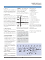
CROSS Rack is fitted with a control
panel on the front part of the unit. This
includes a mimic panel and warning
lights (LED) to indicate the operating
status of the unit in real time.
The status of the sources, the static
switches, the By-pass, the load condition
and the maximum operating temperature
are all monitored continuously.
The functions of the LED are described
in par. 4.3. On the control panel a pushbutton is also present which allows the
user to set the priority between the
sources and a LED which indicates the
current priority.
4.3 Mimic LED display
The controls are located on the front
panel (see Fig.1).
S1
S2
Priority selection button
Press to select system
priority Source S1 or S2
Refer to para 2.1 for more
information about the
behaviour of CROSS Rack
during Priority Selection
Reset button
Press to reset permanent
block (see SCR Open Fault
Alarm)
Note: The Reset command is accepted
only if both sources are within the
tolerances and they are synchronised.
4.5 Output user signals:
• LED 1 & 2 - Priority Source Indicator
LED 1 ON and LED 2 OFF = Priority on S1
LED 1 OFF and LED 2 ON = Priority on S2
• LED 4 Summary Alarm
This LED is illuminated under the
following alarm conditions:
- If at least one source is out of tolerance
- If there is a loss of synchronisation
between the sources
- If the Bypass switch is closed
- If the system is in Over-temperature
- If there is an Output short circuit
- If there is a general SCR fault
- If there is a blocked fan
- If the EPO is active
- If the Backfeed Detector is active
• A summary alarm contact is available
as a cable screw terminal connector,
interfaced with a voltage free relay
contact (NO/NC 1A 220Vac).
The summary alarm is activated
under the conditions described in
4.3. for LED 4.
Digital Outputs list:
• Summary Alarm
• Priority on S1 / S2
• Output Short Circuit
• SCR-Open Fault
• System Over-temperature
• Bypass S1 Closed
• Bypass S2 Closed
• EPO Active
• S1 Out Of Tolerance
• S2 Out Of Tolerance
• Sources Synchronised
• S1 Static Switch Open/Closed
• S2 Static Switch Open/Closed
• Backfeed detector active S1
• Backfeed detector active S2
• Fan failure
Digital outputs are optoisolated signals
(phototransistors); the power supply
has to be provided externally
(maximum current 3mA, maximum DC
voltage +15V).
4.6 Input user signals:
Emergency power Off (EPO). When
the EPO is activated, all the static
switches are opened.
• CROSS Rack is also equipped
with a full set of digital optically
isolated output contacts. These
contacts can be accessed from the
rear panel of the unit on a 25-pin
socket.
• LED 6 & 7 - By-pass Switch Status
Indicators
LED ON = By-pass Switch CLOSED
LED OFF = By-pass Switch OPEN
S1
S2
• LED 8 & 9 - Source S1 and S2
Status Indicators
LED ON = Source OK
LED OFF = Source OUT OF TOLERANCE
• LED 10 - Loss of Synchronisation
Indicator
LED ON = Sources NOT SYNCHRONISED
LED OFF = Sources SYNCHRONISED
MKA4ST0UKCROSSR/CROSS Rack/Rev. 4-12/2007/UK
Figure 1. A view of the display and control panel.
04