1
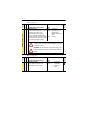
Document Update
PowerFlex 70 User Manual Additions and Corrections
Reference
PowerFlex 70 User Manual, Publication 20A-UM001A-EN-P – August
2000.
New General Precautions
!
!
!
ATTENTION: Risk of injury or equipment damage exists. DPI or
SCANport host products must not be directly connected together via
1202 cables. Unpredictable behavior can result if two or more devices
are connected in this manner.
ATTENTION: A risk of injury or equipment damage exists in
firmware version 1.011 and earlier. When there is a combination of long
shielded motor cables, high source impedance, low speed, light motor
load and parameter 190 [Direction Mode] is set to “Unipolar” or
“Bipolar,” an unexpected change in motor direction may occur. If these
conditions exist, choose one of the following corrective actions:
• Set parameter 190 to “Reverse Dis”
• Set parameters 161 and 162 to “Disabled”
• Install a properly sized Dynamic Brake resistor
ATTENTION: Nuisance tripping may occur in firmware version
1.011 and earlier due to unstable currents. When using a motor that is
connected for a voltage that is different from the drive (e.g., using a
230V connected motor with a 460V drive) the following adjustment
must be made to “Stability Gain” using DriveExplorer software and a
personal computer.
Motor Nameplate Voltage
--------------------------------------------------------------- × 128
Drive Rated Voltage
Any adjustment made to “Stability Gain” must be manually restored if
the drive is reset to defaults or is replaced.
If unstable currents are still present after making the adjustment,
contact the factory for assistance.
2
!
ATTENTION: The “adjust freq” portion of the bus regulator function
is extremely useful for preventing nuisance overvoltage faults resulting
from aggressive decelerations, overhauling loads, and eccentric loads.
It forces the output frequency to be greater than commanded frequency
while the drive's bus voltage is increasing towards levels that would
otherwise cause a fault; however, it can also cause either of the
following two conditions to occur.
1. Fast positive changes in input voltage (more than a 10% increase
within 6 minutes) can cause uncommanded positive speed changes;
however an “OverSpeed Limit” fault will occur if the speed reaches
[Max Speed] + [Overspeed Limit]. If this condition is unacceptable,
action should be taken to 1) limit supply voltages within the
specification of the drive and, 2) limit fast positive input voltage
changes to less than 10%. Without taking such actions, if this operation
is unacceptable, the “adjust freq” portion of the bus regulator function
must be disabled (see parameters 161 and 162).
2. Actual deceleration times can be longer than commanded
deceleration times; however, a “Decel Inhibit” fault is generated if the
drive stops decelerating altogether. If this condition is unacceptable, the
“adjust freq” portion of the bus regulator must be disabled (see
parameters 161 and 162). In addition, installing a properly sized
dynamic brake resistor will provide equal or better performance in most
cases.
Note: These faults are not instantaneous and have shown test results
that take between 2 and 12 seconds to occur.
3
Revised Attention Statement
Refer to page 1-9
!
ATTENTION: A contactor or other device that routinely disconnects
and reapplies the AC line to the drive to start and stop the motor can
cause drive hardware damage. The drive is designed to use control input
signals that will start and stop the motor. If an input device is used
occasionally, an auxiliary contact on that device should also be wired to
a digital input programmed as an “Enable” function. The input device
must not exceed one operation per minute or drive damage will occur.
Bipolar Wiring Diagram
Replaces the diagram on page 1-13.
Input/Output
Analog Voltage
Input - Bipolar(1)
±10V Input 100 ohm input
impedance
Connection Example(2)
Standard Bipolar
Joystick Bipolar
18
18
19
361
to
366
19
or
22
-10V Com +10V
Power Source
(1)
(2)
Refer to the Attention statement on page 1-9 for important bipolar wiring information.
Examples are based on factory default parameter settings. Refer to previous page for parameters
that are related to the individual inputs/outputs.
Start Up Menu
Replaces diagram on page 2-3.
Main Menu:
Start-Up
Input Voltage
Motor Data and
Ramp Times
Motor Tests
Speed Limits
Configure for
Alternate Input
Voltage
Enter Motor NP
Data, Stop Mode,
Accel/Decel
Ramp Times
Optimize Torque
and
Verify Direction
Set Min/Max
Speed and
Direction Control
Speed Control
Start/Stop/I/O
Configure
Configure
Source, Value
Control Method
and Scale for
(2 Wire/3 Wire), I/O,
Speed References Digital Inputs/Outputs
and Analog Outputs
Done /
Exit
4
New Important Notes About Parameter Groups
No. Parameter Name and Description
Related
Group
Slip Comp
File C
Refer to page 3-15.
Values
Important: Parameters in the Slip Comp Group are used to enable and tune the
Slip Compensation Regulator. In order to allow the Slip Compensation Regulator
to control drive operation, parameter 080 [Speed Mode] must be set to 1 “Slip
Comp”.
No. Parameter Name and Description
Related
Group
Process PI
File C
Refer to page 3-15.
Values
Important: Parameters in the Process PI Group are used to enable and tune the
PI Loop. In order to allow the PI Loop to control drive operation, parameter 080
[Speed Mode] must be set to 2 “Process PI”.
Corrections To Parameters
No. Parameter Name and Description
002 [Commanded Freq]
Value of the active frequency command.
Values
Default:
Related
Group
File A
Refer to page 3-8.
Read Only
Min/Max: –/+[Maximum Speed]
Display: 0.1 Hz
No. Parameter Name and Description
016 [Analog In1 Value]
017 [Analog In2 Value]
Value of the signal at the analog inputs.
Values
Default:
Related
Group
File A
Refer to page 3-8.
Read Only
Min/Max: 4.000/20.000 mA
–/+10.000V
Display: 0.001 mA or 0.001 Volt
5
No. Parameter Name and Description
045 [Motor NP Power]
Set to the motor nameplate rated power.
32
Values
Default:
Related
Group
File B
Refer to page 3-9.
Based on Drive Type
046
Min/Max: 0.0/100.0
Display: See [Mtr NP Pwr Units]
No. Parameter Name and Description
047 [Motor OL Hertz]
Values
Default:
Related
Group
File B
Refer to page 3-10.
Motor NP Hz/3
Selects the output frequency below which Min/Max: 0.0/Motor NP Hz
the motor operating current is derated.
Display: 0.1 Hz
The motor thermal overload will generate
a fault at lower levels of current.
042
220
No. Parameter Name and Description
055 [Maximum Freq]
Values
Default:
Related
Group
File B
Refer to page 3-10.
110.0 or 130.0 Hz
083
Sets the highest frequency the drive will Min/Max: 5.0/400.0 Hz
output.
Display: 0.1 Hz
Refer to parameter 083 [Overspeed Limit].
Related
No. Parameter Name and Description
Values
056 [Compensation]
Enables/disables correction options.
En
a
Re ble J
flec erk
tW
ave
Group
File B
Refer to page 3-10.
x x x x x x x x x x x x x x 1 1
15 14 13 12 11 10 9 8 7 6 5 4 3 2 1 0
Nibble 4
Nibble 3
Nibble 2
Nibble 1
Bit #
Factory Default Bit Values
1 =Enabled
0 =Disabled
x =Reserved
6
No. Parameter Name and Description
DYNAMIC CONTROL (File D)
Stop/Brake Modes
158 [DC Brake Level]
Values
Default:
Related
Group
File D
Refer to page 3-18.
[Rated Amps]
Defines the maximum DC brake current in Min/Max: 0/[Rated Amps] × 1.5
percentage of drive rated current.
(Equation yields
approximate maximum
The DC braking voltage used in this
value.)
function is created by a PWM algorithm
and may not generate the smooth holding Display: 0.1 Amps
force needed for some applications. Refer
to the PowerFlex Reference Manual.
!
ATTENTION: If a hazard of injury due to movement of equipment
or material exists, an auxiliary mechanical braking device must be
used to stop the motor.
!
ATTENTION: This feature should not be used with synchronous or
permanent magnet motors. Motors may be demagnetized during
braking.
No. Parameter Name and Description
163 [DB Resistor Type]
Selects whether the internal or an
external DB resistor will be used.
Values
Default:
Options:
Related
File D
Stop/Brake Modes Group
Refer to page 3-19.
0
“Internal Res”
0
1
2
“Internal Res”
“External Res”
“None”
161
162
7
No. Parameter Name and Description
Related
Group
File E
Refer to page 3-23.
Values
211 [Drive Alarm 1]
212
De
c
Drv el Inh
i
Drv OL L bt
OL vl 2
Lvl
1
Int
DB
An Re
lg s
Str in L OH
A o
Po t Pw ss
we rU
Un r Lo p
d
s
Pre erVo s
chr ltag
gA e
ctv
Diagnostics
UTILITY (File E)
Alarm conditions that currently exist in the drive.
x x x x x x 0 0 0 x 0 0 0 0 0 0
15 14 13 12 11 10 9 8 7 6 5 4 3 2 1 0
Nibble 4
Nibble 3
Nibble 2
Nibble 1
Bit #
1 =Condition True
0 =Condition False
x =Reserved
No. Parameter Name and Description
Related
Group
File E
Refer to page 3-27.
Values
238 [Fault Config 1]
De
c
Au el Inh
tR i
Sh st T bt
e ri
Mo ar Pi es
tor n
Ov
erL
Un
d
de
Po rVo
we ltag
rL e
oss
UTILITY (File E)
Faults
Enables/disables annunciation of the listed faults.
x x x x x x x x x 1 0 0 1 x 1 0
15 14 13 12 11 10 9 8 7 6 5 4 3 2 1 0
Nibble 4
Nibble 3
Nibble 2
Nibble 1
Bit #
Factory Default Bit Values
1 =Enabled
0 =Disabled
x =Reserved
No. Parameter Name and Description
Related
Group
File E
Refer to page 3-28.
Values
259 [Alarm Config 1]
De
c
Drv el Inh
i
Drv OL L bt
OL vl 2
Lvl
1
Int
D
An BRe
lg i s O
Str n L H
A o
Po t Pw ss
w r
Un er Lo Up
d
s
Pre erVo s
chr ltag
gA e
ctv
Alarms
UTILITY (File E)
Enables/disables alarm conditions that will initiate an active drive alarm.
x x x x x x 1 1 1 x 1 1 1 1 1 1
15 14 13 12 11 10 9 8 7 6 5 4 3 2 1 0
Nibble 4
Nibble 3
Nibble 2
Nibble 1
Bit #
Factory Default Bit Values
1 =Enabled
0 =Disabled
x =Reserved
8
No. Parameter Name and Description
342 [Analog Out1 Sel]
Values
Default:
Options:
Analog Outputs
INPUTS & OUTPUTS (File J)
Selects the source of the value that drives Options:
the analog output.
0
1
2
3
4
5
6
7
8
9
10
11
12
13
“Output Freq”
“Commanded Freq”
“Output Amps”
“Torque Amps”
“Flux Amps”
“Output Power”
“Output Volts”
“DC Bus Volts”
“PI Reference”
“PI Feedback”
“PI Error”
“PI Output”
“%Motor OL”
“%Drive OL”
Related
Group
File J
Refer to page 3-34.
0
“Output Freq”
See Table
[Analog Out1 Lo] Value
[Analog Out1 Hi] Value
[Analog Out Absolut]
= Disabled
[Analog Out Absolut]
= Enabled
–[Maximum Freq]
–[Maximum Speed]
0 Amps
–200% Rated
0 Amps
0 kW
0 Volts
0 Volts
–100%
–100%
–100%
–100%
0%
0%
0 Hz
0 Hz
0 Amps
0 Amps
0 Amps
0 kW
0 Volts
0 Volts
0%
0%
0%
0%
0%
0%
+[Maximum Freq]
+[Maximum Speed]
200% Rated
200% Rated
200% Rated
200% Rated
120% Rated
200% Rated
100%
100%
100%
100%
100%
100%
001
002
003
004
005
007
006
012
135
136
137
138
220
219
No. Parameter Name and Description
343 [Analog Out1 Hi]
Sets the analog output value when the
source value is at maximum.
344 [Analog Out1 Lo]
Sets the analog output value when the
source value is at minimum.
Values
Default:
Related
Group
File J
Refer to page 3-34.
10.0 Volt
Min/Max: 0.0/10.0 Volts
Display: 0.1 Volt
Default: 0.0 Volt
342
342
Min/Max: 0.0/10.0 Volts
Display: 0.1 Volt
No. Parameter Name and Description
363 [Digital In3 Sel]
Selects the function for the digital inputs.
Values
Default:
Related
Group
File J
Refer to page 3-35.
18
“Auto/ Manual”
9
No. Parameter Name and Description
381 [Dig Out1 Level]
385 [Dig Out2 Level]
Sets the relay activation level for options
10 – 15 in [Digital Outx Sel]. Units are
assumed to match the above selection
(i.e. “At Freq” = Hz, “At Torque” = Amps).
Values
Default:
Related
Group
File J
Refer to page 3-36.
0.0
0.0
380
Min/Max: 0.0/819.2
Display: 0.1
Correction To Fault Action
Fault
Analog In Loss
No.
29
Type(1)
Refer to page 4-4.
➀
➂
➁
Anlg Cal Chksum 108
(1)
Description
An analog input is configured to
fault on signal loss. A signal loss
has occurred.
Configure with [Anlg In 1, 2 Loss]
on page 3-33.
The checksum read from the
analog calibration data does not
match the checksum calculated.
Action
1. Check parameters.
2. Check for broken/loose
connections at inputs.
Replace drive.
See page 4-1 for a description of fault types.
Fault
Decel Inhibit
(1)
No.
24
Type(1)
New Fault
➂
Description
The drive is not following a
commanded deceleration
because it is attempting to limit
bus voltage.
See page 4-1 for a description of fault types.
Action
1. Verify input voltage is within drive
specified limits.
2. Verify system ground impedance
follows proper grounding
techniques.
3. Disable bus regulation and/or
add dynamic brake resistor and/
or extend deceleration time.
10
Renumbered Testpoint Codes and Functions
Refer to page 4-10.
Code Selected in
[Testpoint x Sel]
1
2
3
4
5
6
7
8
9
10
11-99
Function Whose Value is
Displayed in [Testpoint x Data]
DPI Error Status
Heatsink Temperature
Active Current Limit
Active PWM Frequency
Lifetime MegaWatt Hours
Lifetime Run Time
Lifetime Powered Up Time
Lifetime Power Cycles
Life MegaWatt Fraction
Life MegaWatt Fraction Units
Reserved for Factory Use
11
Notes:
12
To contact Drives Technical Support . . .
Tel: (1) 262 512-8176, Fax: (1) 262 512-2222
Email: [email protected]
Online: www.ab.com/support/abdrives
Reach us now at www.rockwellautomation.com
Wherever you need us, Rockwell Automation brings together leading
brands in industrial automation including Allen-Bradley controls,
Reliance Electric power transmission products, Dodge mechanical power
transmission components, and Rockwell Software. Rockwell Automation's
unique, flexible approach to helping customers achieve a competitive
advantage is supported by thousands of authorized partners, distributors
and system integrators around the world.
Americas Headquarters, 1201 South Second Street, Milwaukee, WI 53201-2496, USA, Tel: (1) 414 382-2000, Fax: (1) 414 382-4444
European Headquarters SA/NV, Boulevard du Souverain 36, 1170 Brussels, Belgium, Tel: (32) 2 663 0600, Fax: (32) 2 663 0640
Asia Pacific Headquarters, 27/F Citicorp Centre, 18 Whitfield Road, Causeway Bay, Hong Kong, Tel: (852) 2887 4788, Fax: (852) 2508 1846
Publication 20A-DU001B-EN-P – March 2001
307288-Q01
Supersedes November 2000
Copyright 2001 Rockwell International Corporation. All rights reserved. Printed in USA.