1
Allen-Bradley
StrataScan Bar
Code Readers
(Cat. Nos. 2755-LHR-5B,
2755-LHR-3C,
2755-LHR-5C, and
2755-LHR-5BX1)
User
Manual
Important User
Information
Because of the variety of uses for the products described in this
publication, those responsible for the application and use of this
control equipment must satisfy themselves that all necessary steps
have been taken to assure that each application and use meets all
performance and safety requirements, including any applicable laws,
regulations, codes and standards.
The illustrations, charts, sample programs and layout examples
shown in this guide are intended solely for purposes of example.
Since there are many variables and requirements associated with any
particular installation, Allen-Bradley does not assume responsibility
or liability (to include intellectual property liability) for actual use
based upon the examples shown in this publication.
Allen-Bradley publication SGI-1.1, Safety Guidelines for the
Application, Installation, and Maintenance of Solid-State Control
(available from your local Allen-Bradley office), describes some
important differences between solid-state equipment and
electromechanical devices that should be taken into consideration
when applying products such as those described in this publication.
Reproduction of the contents of this copyrighted publication, in
whole or in part, without written permission of Allen-Bradley
Company, Inc., is prohibited.
Throughout this manual we use notes to make you aware of safety
considerations:
!
ATTENTION: Identifies information about practices
or circumstances that can lead to personal injury or
death, property damage or economic loss.
Attention statements help you to:
• identify a hazard
• avoid the hazard
• recognize the consequences
Important:
Identifies information that is critical for successful
application and understanding of the product.
toc–i
Preface
Chapter Objectives . . . . . . . . . . . . . . . . . . . . . . . . . . . . . . . . . . .
Contents of this Manual . . . . . . . . . . . . . . . . . . . . . . . . . . . . . . . .
Conventions Used in this Manual . . . . . . . . . . . . . . . . . . . . . . . . .
Intended Audience . . . . . . . . . . . . . . . . . . . . . . . . . . . . . . . . . . . .
Related Publication . . . . . . . . . . . . . . . . . . . . . . . . . . . . . . . . . . .
Technical Support Services . . . . . . . . . . . . . . . . . . . . . . . . . . . . . .
Introduction to StrataScan
Bar Code Readers
Chapter 1
Hardware Features
Chapter 2
Required Tools and Equipment . . . . . . . . . . . . . . . . . . . . . . . . . . .
Procedures . . . . . . . . . . . . . . . . . . . . . . . . . . . . . . . . . . . . . . . . .
Reader Features . . . . . . . . . . . . . . . . . . . . . . . . . . . . . . . . . . . . .
Holographic Scanning Disc . . . . . . . . . . . . . . . . . . . . . . . . . . . .
Disc Operation . . . . . . . . . . . . . . . . . . . . . . . . . . . . . . . . . .
Reader LEDs . . . . . . . . . . . . . . . . . . . . . . . . . . . . . . . . . . . . .
Interface Box Features . . . . . . . . . . . . . . . . . . . . . . . . . . . . . . . . .
Decoding . . . . . . . . . . . . . . . . . . . . . . . . . . . . . . . . . . . . . . . . . .
Safety Information . . . . . . . . . . . . . . . . . . . . . . . . . . . . . . . . . . . .
Laser Labels . . . . . . . . . . . . . . . . . . . . . . . . . . . . . . . . . . . . . .
Catalog Numbers 2755-LHR-5B and -5BX1 . . . . . . . . . . . . . . . .
Catalog Numbers 2755-LHR-3C and -5C . . . . . . . . . . . . . . . . . .
Scan Beam Strata . . . . . . . . . . . . . . . . . . . . . . . . . . . . . . . . . . . .
Reader Catalog Numbers . . . . . . . . . . . . . . . . . . . . . . . . . . . . . . .
Accessories . . . . . . . . . . . . . . . . . . . . . . . . . . . . . . . . . . . . . . . .
Designing Your System
1–1
1–2
2–1
2–2
2–3
2–3
2–4
2–5
2–6
2–7
2–7
2–7
2–8
2–9
2–9
Chapter 3
Setup Goals . . . . . . . . . . . . . . . . . . . . . . . . . . . . . . . . . . . . . . . .
Symbol Height and Length . . . . . . . . . . . . . . . . . . . . . . . . . . . . . .
Symbol Quality . . . . . . . . . . . . . . . . . . . . . . . . . . . . . . . . . . . . . .
Symbol Orientation . . . . . . . . . . . . . . . . . . . . . . . . . . . . . . . . . . .
Tilt, Pitch, and Skew . . . . . . . . . . . . . . . . . . . . . . . . . . . . . . . . . .
Tilt . . . . . . . . . . . . . . . . . . . . . . . . . . . . . . . . . . . . . . . . . . . . .
Pitch . . . . . . . . . . . . . . . . . . . . . . . . . . . . . . . . . . . . . . . . . . . .
Skew . . . . . . . . . . . . . . . . . . . . . . . . . . . . . . . . . . . . . . . . . . .
Determining Read Range . . . . . . . . . . . . . . . . . . . . . . . . . . . . . . .
Catalog Number 2755-LHR-5B and 2755-LHR-5BX1 . . . . . . . . .
Catalog Numbers 2755-LHR-3C and 2755-LHR-5C . . . . . . . . . .
Installing Your Hardware
P–1
P–1
P–2
P–2
P–2
P–2
3–1
3–2
3–2
3–3
3–3
3–4
3–4
3–4
3–5
3–5
3–5
Chapter 4
RS232 Installations . . . . . . . . . . . . . . . . . . . . . . . . . . . . . . . . . . .
PLC or PC to the Reader . . . . . . . . . . . . . . . . . . . . . . . . . . . . .
PLC or PC to the Reader and Interface Box . . . . . . . . . . . . . . . .
4–2
4–2
4–4
Publication 2755–6.13
toc–ii
Master/slave Installation (Without Interface Box) . . . . . . . . . . . . . . .
PLC or PC to the Reader, Reader to a Second Reader . . . . . . . .
Master/slave Installation (With Interface Box) . . . . . . . . . . . . . . . . .
PLC or PC to the Reader, Interface Box, and a Second Reader . .
Maintenance and
Troubleshooting
Chapter 5
Specifications
Appendix A
Cleaning the Scan Window . . . . . . . . . . . . . . . . . . . . . . . . . . . . . .
Troubleshooting the Readers . . . . . . . . . . . . . . . . . . . . . . . . . . . .
Technical Support Services . . . . . . . . . . . . . . . . . . . . . . . . . . . . . .
StrataScan Bar Code Reader Specifications . . . . . . . . . . . . . . . . .
Interface Box Specifications . . . . . . . . . . . . . . . . . . . . . . . . . . . . .
Power Supply Specifications . . . . . . . . . . . . . . . . . . . . . . . . . . . . .
StrataScan Bar Code Reader Dimensions . . . . . . . . . . . . . . . . . . .
Catalog Number 2755-LHR-5B . . . . . . . . . . . . . . . . . . . . . . . . .
Catalog Numbers 2755-LHR-3C, -5C and -5BX1 . . . . . . . . . . . .
Interface Box Dimensions . . . . . . . . . . . . . . . . . . . . . . . . . . . . . . .
Catalog Number 2755-LHB-1 . . . . . . . . . . . . . . . . . . . . . . . . . .
Power Supply Dimensions . . . . . . . . . . . . . . . . . . . . . . . . . . . . . .
Replacement Part Number 77126-896-01 . . . . . . . . . . . . . . . . .
Mounting Bracket Dimensions . . . . . . . . . . . . . . . . . . . . . . . . . . .
Replacement Part Number 77126-898-01
(for reader 2755-LHR-5B) . . . . . . . . . . . . . . . . . . . . . . . . . . . . .
Replacement Part Number 77126-898-02
(for readers 2755-LHR-3C, -5C and -5BX1) . . . . . . . . . . . . . . . .
Cable Pinouts
A–2
A–3
A–3
A–4
A–4
A–4
A–5
A–5
A–5
A–5
A–6
A–6
A–7
B–2
B–2
B–3
B–4
B–4
B–5
B–6
B–7
B–8
B–9
B–10
Appendix C
Compliance to European Union Directives . . . . . . . . . . . . . . . . . . .
Low Voltage Directive . . . . . . . . . . . . . . . . . . . . . . . . . . . . . . . .
Declaration of Conformity . . . . . . . . . . . . . . . . . . . . . . . . . . . . . . .
Publication 2755–6.13
5–1
5–2
5–5
Appendix B
Reader Pinouts . . . . . . . . . . . . . . . . . . . . . . . . . . . . . . . . . . . . . .
RS-232 Port . . . . . . . . . . . . . . . . . . . . . . . . . . . . . . . . . . . . . .
Interface Box Port . . . . . . . . . . . . . . . . . . . . . . . . . . . . . . . . . .
Power Supply Port . . . . . . . . . . . . . . . . . . . . . . . . . . . . . . . . . .
Hand–Held Port Pinouts . . . . . . . . . . . . . . . . . . . . . . . . . . . . . . . .
Interface Box Pinouts . . . . . . . . . . . . . . . . . . . . . . . . . . . . . . . . . .
Power Supply Pinouts . . . . . . . . . . . . . . . . . . . . . . . . . . . . . . . . .
Reader Master/slave Cable Pinouts . . . . . . . . . . . . . . . . . . . . . . . .
Reader Null Modem Cable Pinouts . . . . . . . . . . . . . . . . . . . . . . . .
Interface Box Cable Pinouts . . . . . . . . . . . . . . . . . . . . . . . . . . . . .
Interface Box Master/slave Cable Pinouts . . . . . . . . . . . . . . . . . . .
European Union Directives
4–8
4–8
4–10
4–10
C–1
C–1
C–2
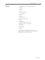
Chapter Objectives
Read this chapter to familiarize yourself with the rest of the manual.
You will learn about:
• contents of this manual
• conventions used in this manual
• intended audience
• related publications
• technical support
Contents of this Manual
The following table describes the contents of this manual.
Chapter
Title
Contents
Preface
Describes the purpose, background, and scope of
this manual. Also specifies the audience for whom
this manual is intended.
1
Introduction to StrataScan
Bar Code Readers
Provides an introduction for the use of the
StrataScan Bar Code Readers.
2
Hardware Features
Provides an overview of the readers and interface
boxes. Includes a description of accessory items.
3
Designing Your System
Gives specific criteria for setup, symbols, symbol
orientation and head range.
4
Installing Your Hardware
Describes how to connect your system hardware.
5
Maintenance and
Troubleshooting
Describes how to maintain and troubleshoot your
system hardware.
Appendix A
Specifications
Provides physical, electrical, environmental, and
functional specifications for the readers and
interface boxes.
Appendix B
Cable Pinouts
Lists the cable pinouts.
Appendix C
European Union
Directives
Provides requirements for readers when used
within the European Union.
Publication 2755-6.13
P–2
Preface
Conventions Used in this
Manual
The following conventions are used throughout this manual.
• Bulleted lists such as this one provide information, not procedural
steps.
• Numbered lists provide sequential steps.
• Italic type is used for emphasis.
• Text within square brackets in this font represent the keys you
press.
Intended Audience
No special knowledge is required to understand this document or use
the StrataScan Bar Code Readers (Catalog Nos. 2755-LHR-5B,
2755-LHR-3C, 2755-LHR-5C and 2755-LHR-5BX1).
!
Related Publication
ATTENTION: Use of controls or adjustments or
performance of procedures other than those specified
herein may result in hazardous laser light exposure.
The following table lists an additional publication related to the
StrataScan Bar Code Readers.
Publication Number
Technical Support Services
Publication 2755-6.13
Title
2755-6.14
StrataSet Programming Software Programming Guide
2755-921
Bar Code Basics
If you have any questions about the StrataScan Bar Code Reader,
please consult this manual first. If you can’t find the answer, contact
your local Allen-Bradley support office or distributor.
Introduction to StrataScan Bar
Code Readers
This chapter can help you to get started using the StrataScan Bar
Code Readers. We base the procedures here on the assumption that
you have an understanding of bar code readers and control
equipment.
Because it is an introduction, this chapter does not contain detailed
explanations about the procedures listed. It does, however, reference
other chapters in this book where you can get more information.
If you have any questions or are unfamiliar with the terms used or
concepts presented in the procedural steps, always read the
referenced chapters and other recommended documentation before
trying to apply the information.
This chapter tells you:
• what tools and equipment you need
• procedures for getting your system up and running
Required Tools and
Equipment
Have the following tools and equipment ready:
• screwdriver
• drill
• tape measure
• personal computer with StrataScan software
Publication 2755-6.13
1–2
Introduction to StrataScan Bar Code Readers
Procedures
1.
Check the contents of shipping boxes.
Unpack the shipping boxes while making sure that the contents include:
•
•
•
•
•
•
•
StrataScan Holographic reader
(Catalog No. 2755–LHR–5B, –3C, –5C or 5BX1)
Reference
Chapter 4
(Installing Your
Hardware)
Mounting bracket (Catalog No. 77126–898–01 or –02)
Power supply (12V dc) (Catalog No. 77126–896–01)
Disk-based Hardware User Manual (Catalog No. 2755–6.13-DISK)
StrataScan Bar Code Readers Instruction Sheet, Pub. No. 2755–5.16
On-line Programming Guide (Catalog No. 2755–6.14-DISK) included with Programming software
Self–Mailer [Catalog No. 41062–002–01(A)]
If the contents are incomplete, call your local Allen-Bradley representative for assistance.
2.
Design the system.
Each application must be evaluated carefully. Successful bar code scanning begins with quality bar
code symbols and the correct number, type, and location of readers, decoders, and package sensors.
Refer to the following when designing your system.
•
•
Publication 2755-6.13
Position the reader at a distance from the symbol that is within the range specified. A read rate
test should be made to verify the range, and also to ensure optimum scanning and decoding.
If a package sensor is used, position it so it can sense the package before the symbol reaches
the scan area.
Reference
Chapter 3
(Designing Your
System)
Introduction to StrataScan Bar Code Readers
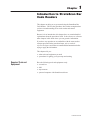
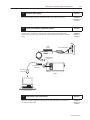
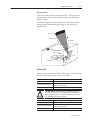
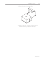
3.
Install the reader.
1–3
Reference
Mount the reader(s) (Catalog Nos. 2755-LHR–3C, 2755-LHR–5C, 2755-LHR–5B, 2755-LHR–5BX1)
to the mounting bracket(s) (Catalog No. 77126–898–01 or 77126–898–02).
Chapter 4
(Installing Your
Hardware)
Mounting
Bracket
Reader
Make sure placement of the mounting bracket allows you to connect the reader to the interface box
(Catalog No. 2755-LHB–1). Skip this information and step #4 if you are not using an interface box.
The standard cable (Catalog No. 2755–LHC–2) from the interface box to the reader is 10 ft. long
(3.05 m).
Interface Box
To interface box (8–pin connector)
To 15-pin
connector
Reader
Publication 2755-6.13
1–4
Introduction to StrataScan Bar Code Readers
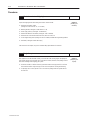
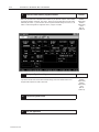
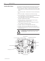
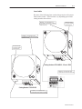
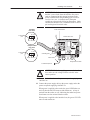
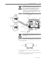
4.
Install the interface box.
Reference
Mount the interface box to your mounting surface after having attached the sensor/relay leads to the
sensor terminal block inside the interface box. Make sure that the 3 power leads from the interface
box power cord are connected to their correct locations on the power terminal block and grounding
posts terminals inside the interface box case.
Screw Holes
Interface
Box
Screw Holes
Sensor Terminal Block
Power Terminal Block
Interface
Box
Grounding posts
Power Cable
Sensor
Cable
To Power Receptacle
Sensor housing
Publication 2755-6.13
Chapter 4
(Installing Your
Hardware)
Introduction to StrataScan Bar Code Readers
5.
Install the power supply.
Reference
Place the power supply (Catalog No. 77126–896–01) within 12 ft. (3.66 m) of the scanner.
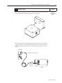
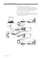
6.
1–5
Chapter 4
(Installing Your
Hardware)
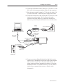
Connect the hardware components together.
Reference
Chapter 4
(Installing Your
Hardware)
If you are using an interface box, connect the reader, power supply and package detect to the
interface box. If you are not using an interface box, connect the reader to the host device and power
supply.
Power
Supply
To Power Receptacle
Grounding Pin
To Reader (9-pin
connector)
To Reader (25-pin
connector)
To PC (9-pin
connector)
Reader
7.
Apply power to the reader system.
After all your hardware components are installed and connected, apply power to the interface box
first, then your reader system.
Reference
Chapter 4
(Installing Your
Hardware)
Publication 2755-6.13
1–6
Introduction to StrataScan Bar Code Readers
8.
Check the reader defaults, program as needed.
Make sure you have DOS or Windows–based software on your personal computer. Run StrataSet
Programming software, Catalog No. 2755–LHS–1. Make sure that communications has been established with your reader. e.g., read a test bar code to verify that the default settings are correct (i.e., the
reader is communicating with the configuration device). Program as needed.
9.
Change configuration settings as necessary.
If you need to set the reader to other than the default settings, refer to the software manual. Exit
Program mode and place the reader in Run mode.
Publication 2755-6.13
10.
Connect the system to host.
11.
Run your application.
Reference
StrataSet
Programming
Software
Programming
Guide
(Pub. No.
2755–6.14)
Reference
StrataSet
Programming
Software
Programming
Guide
(Pub. No.
2755–6.14)
Hardware Features
This chapter describes the features of the StrataScan Bar Code
Readers (Catalog Nos. 2755-LHR-5B, 2755-LHR-3C, 2755-LHR-5C
and 2755-LHR-5BX1) and interface box (Catalog No. 2755-LHB-1).
Included are descriptions of:
• reader features
• interface box features
• decoding
• safety information
• scan beam options
• accessories
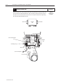
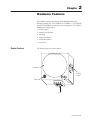
Reader Features
The reader features are shown below.
Scan Window
Mounting
Bracket
Speaker
LEDs
Ports
Publication 2755-6.13
2–2
Hardware Features
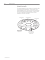
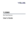
Holographic Scanning Disc
The rotating holographic disc takes the place of a focusing lens, light
collection lens, and a rotating mirror. The disc contains 15 to 21
separate holographic sectors. Each sector has its own focal distance,
light collection aperture, and mirror scan angle. As the disc rotates,
each sector is operational, providing the reader an excellent
opportunity to scan a bar code symbol.
Scanning Element
Large Area Receiver
(for long focal length
holographic lens)
Publication 2755-6.13
Receiving Elements
Small Area Receiver
(for short focal length
holographic lens)
Scanning Element
Hardware Features
2–3
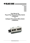
Disc Operation
As the disc rotates, the laser beam hits the disc. The laser beam is
then projected onto the mirror and then projected out through the
reader’s window.
The reflected light travels toward the mirror. The reflected light is
then projected onto the rotating disc where it is detected by an
internal sensor.
Bar Code
Reflected Light
Laser Beam
Detector
Mirror
Scan Disc
Laser
Reader LEDs
There is one green and one red LED on the readers. The table below
provides an explanation of the reader’s LED status.
LED State
Indicates
Solid Red
the reader has power.
Solid Red, Flashing Green
the reader has transmitted a successful read or the
reader is in program mode.
Flashing Red and Green
the reader has a motor failure.
ATTENTION: With a software command, both the
red and green LED’s can exchange their meanings. If
that command is active, then the following table with
the following LED states applies.
!
LED State
Indicates
Solid Green
the reader has power.
Solid Green, Flashing Red
the reader has transmitted a successful read or the
reader is in program mode.
Flashing Green and Red
the reader has a motor failure.
Publication 2755-6.13
2–4
Hardware Features
Interface Box Features
The interface box routes signals between the readers and an external
package detect. The interface box has the following components:
• Power transformer. Supplies a stepped down and isolated voltage
that produces the 12V dc power for the interface box and external
sensor.
• F2 control fuse holder. Contains the 12V dc fuse for the interface
box.
• F1 triac fuse holder. Contains the fuse for the triac output.
• Power terminal block. Provides the input connection point for the
AC line that supplies power to the interface box.
• Triac terminal block. Provides the output connection point for
the reader–controlled power output.
• LED status indicators. Provides the status of power supply,
package detect, and sensor alarm circuits.
• Voltage selector switch. Allows you to configure the interface
box to match the incoming line voltage.
• J1 jumper. Allows you to configure the sensor input.
• J2 jumper. Allows you to configure the sensor input alarm.
• Package detect terminal block. Provides the connection point for
the package detect.
!
ATTENTION: Before applying power to the interface
box, make sure the voltage selector switch is in the
correct position.
Power Transformer
F1 Triac Fuse Holder F2 Control Fuse Holder
Package Detect Terminal Block
J2 Jumper
Power Terminal Block
Triac Terminal
Block
Grounding posts
LED Status Indicators
Publication 2755-6.13
Voltage
Selector
Switch
J1 Jumper
Hardware Features
Decoding
2–5
The readers can decode the following symbologies:
• UPC/EAN
• Codabar
• Code 11
• Code 39
• Code 39 Full ASCII
• Code 39 Mod 43
• Code 93
• Code 128
• Interleaved 2 of 5
• Interleaved 2 of 5 Mod 10
• Paraf
• MSI Plessey
• MSI Plessey Mod 10 Check digit
• MSI Plessey Mod 10/10 Check digit
• UK Plessey
• Airline 2 of 5
• Matrix 2 of 5
• telepen
Refer to Chapter 2 of StrataSet Programming Software
Programming Guide (Publication No. 2755–6.14) for more
information on the code types listed above.
Publication 2755-6.13
2–6
Hardware Features
Safety Information
This equipment has been tested and found to comply with limits for a
Class A digital device, pursuant to Part 15 of the FCC Rules. These
limits are designed to provide reasonable protection against harmful
interference when the equipment is operated in a commercial
environment. This equipment generates, uses and can radiate radio
frequency energy and, if not installed and used in accordance with
the instruction manual, may cause harmful interference to radio
communications. Operation of this equipment in a residential area is
likely to cause harmful interference, in which case the user will be
required to correct the interference at his/her own expense. Any
unauthorized changes or modifications to this equipment could void
the user’s authority to operate this device.
This digital apparatus does not exceed the Class A limits for radio
noise emissions from digital apparatus set out in the Radio
Interference Regulations of the Industry Canada.
!
!
!
!
!
Publication 2755-6.13
ATTENTION: Never attempt to look at the laser
beam, even if the scanner appears to be nonfunctional.
Doing so could result in hazardous laser light exposure.
ATTENTION: Use of controls, adjustments, or
performance of procedures other than those specified
herein may result in hazardous laser light radiation
exposure.
ATTENTION: Never open the scanner in an attempt
to look into the device or to service the laser scanner.
ATTENTION: The use of optical instruments with the
laser equipment will increase eye hazard.
ATTENTION: If it is necessary to disable the scanner
light emission, unplug the power supply’s AC power
plug from its AC power source.
Hardware Features
2–7
Laser Labels
Be aware of the following laser caution, danger and avoid exposure
labels on the readers. Their locations vary depending upon reader
catalog number shown below:
DANGER – Laser light when open.
AVOID DIRECT EXPOSURE TO BEAM
(hidden from view)
AVOID EXPOSURE
Laser light is emitted
from this aperture.
DANGER – Laser light when open.
AVOID DIRECT EXPOSURE TO BEAM
(hidden from view)
AVOID EXPOSURE
Laser light is emitted
from this aperture.
Catalog Numbers 2755-LHR-3C, -5C and - 5BX1
DANGER – Laser light when open.
AVOID DIRECT EXPOSURE TO BEAM
Catalog Number 2755-LHR-5B
DANGER – Laser light when open.
AVOID DIRECT EXPOSURE TO BEAM
Publication 2755-6.13
2–8
Hardware Features
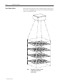
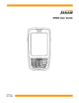
Scan Beam Strata
Scan beams are projected to focus in different strata as shown below.
The various overlapping focus areas give the StrataScan holographic
reader its great depth of field.
Note:
Publication 2755-6.13
This pattern or number of strata
is different for each of the
reader models.
Hardware Features
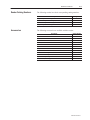
Reader Catalog Numbers
The following readers have their corresponding catalog numbers:
Description
Accessories
2–9
Catalog Number
High density, five laser holographic reader
2755-LHR-5B
Medium density, three laser holographic reader
2755-LHR-3C
Medium density, five laser holographic reader
2755-LHR-5C
High density, five laser holographic reader
2755-LHR-5BX1
The following accessories are available with the readers:
Description
Catalog Number
Interface box
2755-LHB-1
Master/Slave cable for readers
2755-LHC-1
Interface box cable
2755-LHC-2
Master/Slave cable for interface box
2755-LHC-3
Null modem cable for readers
2755-LHC-11
Unterminated communications cable
2755-LHC-12
Replacement cover for 2755-LHR-5B
77126-899-01
Replacement cover for 2755-LHR-3C, -5C and -5BX1
77126-899-02
Replacement mounting bracket for 2755-LHR-5B
77126-898-01
Replacement mounting bracket for 2755-LHR-3C and 2755-LHR-5C
77126-898-02
StrataScan Programming Software
2755-LHS-1
Replacement power supply for the readers
77126-896-01
Publication 2755-6.13
Designing Your System
This chapter provides the information needed to set up a scanner
system correctly. Items include:
• setup goals
• symbol height and length
• symbol quality
• symbol orientation
• tilt, pitch, and skew
• determining read range
Setup Goals
Each application must be evaluated carefully. Successful bar code
scanning begins with quality bar code symbols and the correct
number, type, and location of readers, decoders, and package
sensors. Refer to the following when designing your scanner system.
• Adjust, if necessary, the symbol speed and/or the distance
between bar-coded packages to ensure that the bar code symbol is
being read.
• Position the reader at a distance from the symbol that is within
the range specified. A read rate test should be made to verify the
range, and also to ensure optimum scanning and decoding.
• If a package sensor is used, position it so it can sense the package
before the symbol reaches the scan area.
Publication 2755-6.13
3–2
Designing Your System
Symbol Height and Length
The height is measured from one end of a bar to the other, and its
length is always the distance from one end of the symbol to the other,
including the Quiet Zones. A Quiet Zone is the empty space before
or after the bars, and is usually equal to 10 times the Narrow Element
Width.
H
Symbol Length = L
Symbol
Height = H
Quiet
Zones
L
Quiet Zones
The aspect ratio (symbol height to symbol length) cannot be greater
than 1.7:1 for Catalog No. 2755-LHR-3C and 2.5:1 for
Catalog No. 2755-LHR-5C.
Symbol Quality
A bar code reader cannot reliably read a poor quality symbol. Test
proposed bar code symbol samples to ANSI Standard X3.182-1990,
Bar Code Print Quality Guideline.
• Low-cost verifiers that can test this standard are available from
several companies.
• Symbol samples can be submitted to an independent symbology
testing company.
The ANSI guideline specified six parametric tests plus two pass/fail
tests to determine the printed symbol quality. The tests result in an
overall letter grade of A, B, C, D or F assigned to the symbol. In
general, symbols are most decodable in the A range with diminishing
quality through F. An F or failure occurs because a symbol does not
conform to a legitimate bar code symbology, whereas a D grade has
a better chance of being read. And a C has a still better chance of
being read by more readers than a D. And so on.
Publication 2755-6.13
Designing Your System
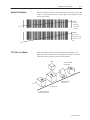
Symbol Orientation
3–3
Bar code symbols must have the correct aspect ratio to be read by the
reader. A scan line must cross every bar, space, and both quiet zones
on the same sweep.
Correct:
All bars are
crossed by a
scan line
Not Correct:
Some bars are not
crossed by a scan
line
Tilt, Pitch, and Skew
Refer to the figure below for various package orientations. Tilt,
pitch, and skew can affect the scan aspect ratio, and as a result, can
affect the reader’s ability to read bar code symbols.
reader
Skewed Package
and Symbol
Pitched Package
and Symbol
Tilted Symbol
Correctly Positioned
Symbol and Package
Publication 2755-6.13
3–4
Designing Your System
Tilt
A symbol is tilted when the symbol’s bars are not 90° to one of the
scan lines. The symbol can be read with any tilt, provided a scan
line passes through all bars and quiet zones on each sweep for the
required minimum number of scans. Tilt may reduce the number of
scans in a given application.
Pitch
A symbol is pitched when the symbol’s bars are at different distances
from the reader. From the reader’s perspective, a pitched symbol
appears to have a smaller narrow element width than it actually has.
This may reduce both the read rate and the read range. However, the
symbol can still be read if the apparent narrow element width is
within the reader’s specifications.
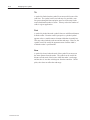
Skew
A symbol is skewed when the ends of the symbol’s bars are not at
the same distance from the reader. The symbol can be read if the
distance of both ends of the bar are within the reader’s read range,
and the skew is less than 40 degrees from the centerline. Unlike
pitch, skew does not affect the read range.
Publication 2755-6.13
Designing Your System
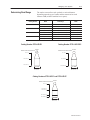
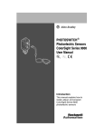
Determining Read Range
3–5
The readers can read bar code symbols at various distances
depending upon the type of reader and the narrowest bar code
element width (width of smallest bar or space).
Minimum Bar Code
Width
Catalog Number
2755-LHR-5B
2755-LHR-3C
2755-LHR-5C
2755-LHR-5BX1
Maximum Scan
Width
Read Range
0.008 in. (0.20 mm)
18 to 38 in. (45.7 to 96.5 cm)
12 in. (30.5 cm)
0.025 in. (0.64 mm)
18 to 38 in. (45.7 to 96.5 cm)
12 in. (30.5 cm)
0.013 in. (0.33 mm)
36 to 78 in. (91.4 to 198.1 cm)
22 in. (55.9 cm)
0.04 in. (1.02 mm)
36 to 78 in. (91.4 to 198.1 cm)
22 in. (55.9 cm)
0.013 in. (0.33 mm)
34 to 64 in. (86.4 to 162.6 cm)
22 in. (55.9 cm)
0.04 in. (1.02 mm)
36 to 78 in. (91.4 to 198.2 cm)
22 in. (55.9 cm)
0.008 in. (0.20 mm)
33 to 43 in. (83.8 to 109.2 cm)
13 in. (33.0 cm)
0.025 in. (0.64 mm)
33 to 43 in. (83.8 to 109.2 cm)
13 in. (33.0 cm)
Catalog Number 2755-LHR-5B
Catalog Number 2755–LHR–5BX1
Scanner
Scanner
Distance From Front of Scanner
Distance From Front of Scanner
0 in. (0 cm)
0 in. (0 cm)
18 in. (45.7 cm)
33 in. (83.8 cm)
38 in. (96.5 cm)
43 in. (109.2 cm)
Scan Width
Scan Width
12 in. (30.5 cm)
12 in. (30.5 cm)
Catalog Numbers 2755-LHR-3C and 2755-LHR-5C
Scanner
Distance From Front of Scanner
0 in. (0 cm)
34 in. (86.4 cm)
36 in. (91.4 cm)
64 in. (162.6 cm)
78 in. (198.2 cm)
Scan Width
24 in. (61 cm)
Publication 2755-6.13
Installing Your Hardware
This chapter provides the information needed to install the readers,
their mounting brackets, their power supplies, and interface boxes.
Items include:
• RS-232 installations
• master/slave installations
Because of the variety of uses for the information, users of and those
responsible for applying this information must satisfy themselves as
to the acceptability of each application and use of the program. In no
event will Allen-Bradley Company be responsible or liable for
indirect or consequential damages resulting from the use of
application of this information.
The examples shown in this document are intended solely to
illustrate the principles of the bar code reader and some of the
methods used to apply them. Particularly because of the many
requirements associated with any particular installation,
Allen-Bradley Company cannot assume responsibility or liability for
actual use based upon the illustrative uses and applications.
Publication 2755-6.13
4–2
Installing Your Hardware
RS232 Installations
Refer to the following sections to install your system hardware,
based on the type of equipment you select:
PLC or PC to the Reader
1. Make sure your system is planned properly. Refer to Chapter 3
for information about planning your system.
2. Refer to Appendix A for dimensions of readers, mounting
brackets, power supplies, and interface boxes. Cable pinouts are
shown in Appendix B.
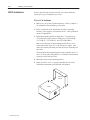
3. Install the mounting bracket (Catalog Nos. 77126-898-01 or
77126-898-02) for the readers (Catalog Nos. 2755-LHR-5B,
2755-LHR-3C, 2755-LHR-5C, and 2755-LHR-5BX1).
Make sure placement of the mounting bracket allows you to
connect the reader to the PLC or PC and power supply. Also
make sure bracket placement provides the correct read range for
the reader.
The maximum cable length from the reader to another device is
50 ft. (15.24 m) when using RS232. Use RS422 when distances
reach up to 2000 feet (609.6 m).
4. Mount the reader to the mounting bracket.
5. Install your PLC or PC. For proper installation refer to the
installation information provided with each product.
Mounting
Bracket
Reader
Publication 2755-6.13
Installing Your Hardware
4–3
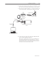
6. Connect the null modem cable (Catalog No. 2755-LHC-11) to the
PLC or PC (9–pin connector) and the reader (25–pin connector).
7. Place the power supply (Catalog No. 77126-896-01) within 12 ft.
(3.66 m) of the reader. Connect the power supply to the reader.
Power
Supply
To Power Receptacle
Grounding Pin
77126–896–01
To Reader (9-pin
connector)
2755–LHC–11
To Reader (25-pin
connector)
To PC (9-pin
connector)
Reader
8. Connect the power supply cable to the power supply and to the
power receptacle supplying 100/240V ac.
When power is applied to the reader, the green LED flashes on
and off, then the red LED turns on and remains on. A beep is
emitted from the reader as well, indicating the reader has power.
Scan beams are also emitted from the reader.
Publication 2755-6.13
4–4
Installing Your Hardware
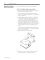
PLC or PC to the Reader and Interface Box
1. Make sure your system is planned properly. Refer to Chapter 3
for information about planning your system.
2. Refer to Appendix A for dimensions of readers, mounting
brackets, power supplies, and interface boxes. Cable pinouts are
shown in Appendix B.
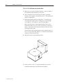
3. Install the mounting bracket (Catalog Nos. 77126-898-01 or
77126-898-02) for the readers (Catalog Nos. 2755-LHR-5B,
2755-LHR-3C, 2755-LHR-5C, and 2755-LHR-5BX1).
Make sure placement of the mounting bracket allows you to
connect the reader to the PLC or PC, interface box, and power
supply. Also make sure bracket placement provides the correct
read range for the reader.
The maximum cable length from the reader to another device is
50 ft. (15.24 m) when using RS232. Use RS422 when distances
reach up to 2000 feet (609.6 m).
4. Mount the reader to the mounting bracket.
Mounting
Bracket
Reader
5. Install your PLC or PC. For proper installation refer to the
installation information provided with each product.
Publication 2755-6.13
Installing Your Hardware
4–5
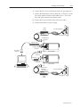
6. Connect the null modem cable (Catalog No. 2755-LHC-11) to the
PLC or PC (9–pin connector) and the reader (25–pin connector).
7. Place the power supply (Catalog No. 77126-896-01) within 12 ft.
(3.66 m) of the reader. Connect the power supply to the reader.
8. Connect the interface box cable (Catalog No. 2755-LHC-2) to the
interface box and the reader. The 15–pin end of the cable
connects to the reader and the 8–pin end to the interface box.
Make sure you lock into place the interface box end of the cable.
Power
Supply
To Power Receptacle
Grounding Pin
77126–896–01
To Reader (9-pin
connector)
To PC (9-pin
connector)
2755–LHC–11
8–pin connector
To Reader (25-pin
connector)
To Reader (15-pin
connector)
Reader
2755–LHC–2
Interface Box
9. Connect your sensor (PhotoSwitch 6000 or 9000 Series) to the
interface box by attaching the sensor leads to the sensor terminal
block inside the interface box. The sensor itself will have the
proper connection scheme imprinted on its housing. Follow the
method shown there. For instance, brown to +12V out, white to
sink-in, blue to common, black to source. (Black is often
disregarded.)
Publication 2755-6.13
4–6
Installing Your Hardware
Sensor Terminal Block
Interface
Box
Common
Sensor
Cable
+12V out
Sink in
Sensor housing
10. Mount the interface box (Catalog No. 2755-LHB-1). Its
dimensions are shown in Appendix A.
Screw Holes
Publication 2755-6.13
Screw Holes
Installing Your Hardware
!
ATTENTION: Before connecting power, make sure
that the 3 power leads from the interface box power
cord are connected to their proper locations on the
power terminal block and grounding posts inside the
interface box case. A domestic and a European
example are shown in the following illustration. Make
sure that the interface box is connected to an ac source
per local/regional electrical codes.
US 3–Wire
Color Code
To Grounding
post
4–7
Power Terminal Block
N Ln In
Interface Box Cover
Grn Blk Wht
European 3–Wire
Color Code
To Grounding
post
N Ln In
Grounding posts
Grn/Yel Blue Brn
Power Cable
Voltage Selector Switch
To Power Receptacle
!
ATTENTION: Before applying power to the interface
box, make sure the voltage selector switch is in the
correct position.
11. Connect the interface box to the power receptacle supplying
100/240V ac.
12. Connect the power supply cable to the power supply and to the
power receptacle supplying 100/240V ac.
When power is applied to the reader, the green LED flashes on
and off, then the red LED turns on and remains on. A beep is
emitted from the reader as well, indicating the reader has power.
Scan beams are also emitted from the reader.
When power is applied to the interface box, the green 12V LED
turns on and remains on.
Publication 2755-6.13
4–8
Installing Your Hardware
Master/slave Installation
(Without Interface Box)
Refer to the following steps to install your system hardware:
PLC or PC to the Reader, Reader to a Second Reader
1. Make sure your system is planned properly. Refer to Chapter 3
for information about planning your system.
2. Refer to Appendix A for dimensions of readers, mounting
brackets, power supplies and interface boxes. Cable pinouts are
shown in Appendix B.
3. Install the mounting brackets (Catalog Nos. 77126-898-01 or
77126-898-02) for the readers (Catalog Nos. 2755-LHR-5B,
2755-LHR-3C, 2755-LHR-5C and 2755-LHR-5BX1).
Make sure placement of the mounting brackets allows you to
connect the first reader to the PLC or PC, interface box, and
power supply. It should also allow you to connect the second
reader to the interface box and a power supply. Also make sure
bracket placement provides the correct read range for both
readers.
The maximum cable length from the reader to another device is
50 ft. (15.24 m) when using RS232. Use RS422 when distances
reach up to 2000 feet (609.6 m).
4. Mount each reader to its mounting bracket.
Mounting
Bracket
Reader
5. Install your PLC or PC. For proper installation refer to the
installation information provided with each product.
Publication 2755-6.13
Installing Your Hardware
4–9
6. Connect the PLC or PC to the master reader (25–pin connector).
7. Connect the Master/Slave cable (Catalog No. 2755-LHC-1) to the
first reader (master) and the second reader (slave). The 15-pin
end of the cable connects to the master reader.
8. Connect the 25-pin end of the cable to the slave reader.
9. Connect each reader to a power supply.
Power
Supply
To Power Receptacle
Grounding Pin
77126–896–01
To Reader (9-pin
connector)
2755–LHC–11
To Reader (25-pin
connector)
To PC (9-pin
connector)
Master Reader
To Reader (15-pin
connector)
2755–LHC–1
To Reader (25-pin
connector)
Slave Reader
To Reader (9-pin
connector)
77126–896–01
Power
Supply
To Power Receptacle
Grounding Pin
Publication 2755-6.13
4–10
Installing Your Hardware
!
ATTENTION: To prevent unsuccessful programming
of your master/slave scanner configuration, follow this
setup sequence when installing master/slave option:
1. Connect master and slave scanners with the
appropriate master/slave cable.
2. Connect Allen–Bradley StrataScan Configuration
software to the master scanner.
3. Apply power to the master/slave units.
4. Program the master scanner as you would a
regular scanner with the StrataScan Configuration
software.
5. The master scanner automatically programs the
slave to the same parameters.
10. Connect each power supply cable to each power supply and to the
power receptacle supplying 100/240V ac.
When power is applied to each reader, the green LED flashes on
and off, then the red LED turns on and remains on. A beep is
emitted from each reader as well, indicating the reader has power.
Scan beams are also emitted from each reader.
Master/slave Installation
(With Interface Box)
Refer to the following steps to install your system hardware:
PLC or PC to the Reader, Interface Box, and a Second Reader
1. Make sure your system is planned properly. Refer to Chapter 3
for information about planning your system.
2. Refer to Appendix A for dimensions of readers, mounting
brackets, power supplies and interface boxes. Cable pinouts are
shown in Appendix B.
3. Install the mounting brackets (Catalog Nos. 77126-898-01 or
77126-898-02) for the readers (Catalog Nos. 2755-LHR-5B,
2755-LHR-3C, 2755-LHR-5C, and 2755-LHR-5BX1).
Make sure placement of the mounting brackets allows you to
connect the first reader to the PLC or PC, interface box, and
power supply. It should also allow you to connect the second
reader to the interface box and a power supply. Also make sure
bracket placement provides the correct read range for both
readers.
The maximum cable length from the reader to another device is
50 ft. (15.24 m) when using RS232. Use RS422 when distances
reach up to 2000 feet (609.6 m).
Publication 2755-6.13
Installing Your Hardware
4–11
4. Mount each reader to its mounting bracket.
Mounting
Bracket
Reader
5. Install your PLC or PC. For proper installation refer to the
installation information provided with each product.
Publication 2755-6.13
4–12
Installing Your Hardware
6. Connect the PLC or PC to the first reader.
7. Connect the Master/Slave Interface Box Cable (Catalog No.
2755-LHC-3) to the first reader (master) and the interface box.
Make sure you lock into place the interface box end of the cable.
The 15-pin end of the cable connects to the master reader.
8. Connect each reader to a power supply.
9. Connect the Master/Slave Interface Box Cable (Catalog No.
2755-LHC-3) to the second reader (slave). The 25-pin end of the
cable connects to the slave reader.
Power
Supply
To Power Receptacle
Grounding Pin
77126–896–01
To Reader (9-pin
connector)
To PC (9-pin
connector)
2755–LHC–11
To interface box (8–pin connector)
2755–LHC–3
To Reader (25-pin
connector)
To Reader (15-pin
connector)
Master Reader
To Reader (25-pin
connector)
Slave Reader
To Reader (9-pin
connector)
To Power Receptacle
77126–896–01
Power
Supply
Publication 2755-6.13
Grounding Pin
Installing Your Hardware
!
ATTENTION: Before connecting power, make sure
that the 3 power leads from the interface box power
cord are connected to their proper locations on the
power terminal block and grounding posts inside the
interface box case. A domestic and a European
example are shown in the following illustration. Make
sure that the interface box is connected to an ac source
per local/regional electrical codes.
US 3–Wire
Color Code
To Grounding
post
4–13
Power Terminal Block
N Ln In
Interface Box Cover
Grn Blk Wht
European 3–Wire
Color Code
To Grounding
post
N Ln In
Grounding posts
Grn/Yel Blue Brn
Power Cable
To Power Receptacle
!
ATTENTION: Before applying power to the interface
box, make sure the voltage selector switch is in the
correct position.
10. Mount the interface box. The dimensions of the interface box are
shown in Appendix A.
Screw Holes
Screw Holes
11. Connect the interface box to the power receptacle supplying
100/240V ac.
12. Connect each power supply cable to each power supply and to the
power receptacle supplying 100/240V ac.
Publication 2755-6.13
4–14
Installing Your Hardware
When power is applied to each reader, the green LED flashes on
and off, then the red LED turns on and remains on. A beep is
emitted from each reader as well, indicating the reader has power.
Scan beams are also emitted from each reader.
When power is applied to the interface box, the green 12V LED
turns on and remains on.
Publication 2755-6.13
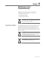
Maintenance and
Troubleshooting
This chapter provides information on how to maintain and
troubleshoot your StrataScan hardware. Items include:
• cleaning the scan window
• troubleshooting the readers
• contacting Technical Support
!
Cleaning the Scan Window
CAUTION!: Before cleaning window, make sure that
power to the reader is off. Failure to disconnect power
may cause exposure to laser light.
Carefully clean the window by first removing loose particles of dirt
with canned ultra–filtered air. Then use an optical quality cloth
moistened with an optical quality cleaning fluid for plastic lenses.
Wipe the window in a single direction, turning the cloth to a clean
side after each wipe(don’t wipe cloth back and forth across window).
Do not leave streaks.
!
!
ATTENTION: Do not use abrasive materials such as
disposable wipes and facial tissue. Do not use solvents
like alcohol or acetone. These materials will damage
the window and the finish on the reader.
ATTENTION: The reader has no serviceable parts.
Do not open the housing of the reader.
Publication 2755-6.13
5–2
Maintenance and Troubleshooting
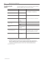
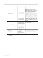
Troubleshooting the
Readers
The following table provides a list of the most common operating
problems, probable causes, and corrective actions.
Problem
No blinking Green LED
Possible Cause (s)
No power
Corrective Action
No Motor Spin
No power
Blinking Green LED
Motherboard problem
No Motor Spin
1. Motherboard problem
Contact an Allen–Bradley service representative.
2. Reader is in motor failure
condition.
1. Motor may be defective.
Contact an Allen–Bradley service representative①.
Check transformer, outlet and power strip.
LED’s toggle back and forth and unit
produces “razzes”
2. Too much vibration or
jarring
Decode module failed
communications with the
motherboard
Isolate reader from vibration.
Power-up OK, reads OK but does not
communicate properly to host.
COM Port at host not working
or is configured improperly
As a quick test, put reader into Program mode
through StrataScan software. If successful, the
RECEIVE and TRANSMIT lines are working②.
Does not communicate properly to host
Cable not connected to the
proper COM Port
Check cable connections.
Reader makes “razz” tone during
power-up
①
②
Contact an Allen-Bradley service representative.
If reader is in an environment subject to much vibration or sudden jarring, the motor may experience a motor failure
condition temporarily. The unit will recover after the external stimulus has disappeared.
If the reader is not configured for host RTS/CTS, this test is enough to verify that the reader, communication cable
and host are all working properly. When the reader is configured for host RTS/CTS, temporarily disable this function in
the reader and try the quick test above. If the reader works with RTS/CTS disabled, and fails when RTS/CTS is
re–enabled, there is a problem with either the RTS or CTS line or both. Contact an Allen–Bradley service rep.
Table continued on the next page.
Publication 2755-6.13
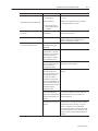
Maintenance and Troubleshooting
Problem
Reader does not enter Program mode
Possible Cause (s)
5–3
Corrective Action
1. Host COM Port not
working properly
1. Check to see if cable connection to COM Port is
correct.
2. Wrong COM Port
2. Make sure COM Port selection in StrataScan
configuration software is correct.
3. Communication cable is
not connected properly or
is defective
Host receiving data but data does not
look correct
Interface format
incompatibility
Check that the reader and host are configured for
the same interface format.
Characters are being dropped
No inter–character delay
Add some inter–character delay to the transmitted
output. Program this into reader through the
StrataScan configuration software.
Unit powers up properly and lasers
come on, but still does not read.
Reading a particular
symbology that has been
deselected.
Verify that the bar code being read is selected.
Reader has been
programmed for a character
length lock or for a minimum
length and the bar code
being read does not satisfy
the programmed criteria.
Verify that bar code being read falls into the criteria.
Reader has been configured
for Package Detect Support,
but is not receiving a
Package Detect signal
Verify that the device used to generate the package
detect input is working properly.
Reader reads and transmits a
bar code, but the reader
hangs up (green LED comes
on and stays on) after the
first read. The reader is
configured to support some
form of host handshaking, but
is not receiving the signal. If
the reader is setup to support
ACK/NAK, RTS/CTS,
XON/XOFF or D/E.
Verify that host is supporting the handshaking
properly.
Package Detect is selected
and the Package Detect
signal seems to be generated
properly, but the reader is not
reading.
Read duration may be set too short. Read duration
can be set from 100 msec to 8.9 sec. Make sure
that read duration time is set correctly for the
particular application.
Reader reads and transmits,
but the data is not correct at
the host.
Verify that reader’s data format matches that
required by the host. Make sure that the reader is
connected to the proper host port. As a rule of
thumb, if configurations can be downloaded
successfully to the reader, the cable and port setup
are physically working. The only exception is with
RTS/CTS, which is not used during the download
sequence.
Table continued on the next page.
Publication 2755-6.13
5–4
Maintenance and Troubleshooting
Problem
Possible Cause (s)
1. Print quality of the bar
code is suspect.
Cannot read bar code➂
2. The aspect ratio of the bar
code is out of tolerance.
3. The bar code may have
been printed incorrectly.
DOS error code:
# 68 – Device unavailable
DOS error code:
# 24 – Device timeout
➂
Corrective Action
To verify the basic operation of the reader,
configure the reader with the standard default
settings. To do this, enter the reader’s Program
Mode from StrataScan’s main menu. Press
Enter at the Configuration screen menu choice.
From the Configuration screen, press F5 to
download the configuration to the reader. The
reader is now setup to read all common
symbologies with a minimum of 4 characters. Try
reading a typical UPC bar code on a typical office
supply product or food product. If the reader reads
the bar code presented, the basic operation of the
reader is verified. The problem is within the reader
setup. Determine how the reader should be
configured. Contact an Allen–Bradley service rep.
for help. If not possible, then make sure all settings
are correct.
This error occurs when a file
or COM Port is accessed
(that according to the system)
does not exist. Normally this
occurs when the COM Port is
used that is attached to a
wrong type of peripheral. Or
when there is a problem with
the COM Port itself.
Try using another COM Port, if available. If all else
fails, reboot the system.
This error occurs when the
host did not receive
information from the I/O
device within a
predetermined amount of
time.
Check that the reader is connected to the correct
COM Port and verify that the COM Port is working
correctly. If all else fails, reboot the system.
Many other scenarios can cause reading problems. If problems persist, contact an Allen–Bradley service
representative.
Publication 2755-6.13
Maintenance and Troubleshooting
Technical Support Services
5–5
If you have any questions about the StrataScan Bar Code Reader,
please consult this manual first. If you can’t find the answer, contact
your local Allen-Bradley support office or distributor.
Publication 2755-6.13
This appendix provides the specifications and dimensions for the:
• StrataScan Bar Code Readers (Catalog Nos. 2755-LHR-5B,
2755-LHR-3C, 2755-LHR-5C and 2755–LHR–5BX1)
• interface box (Catalog No. 2755-LHB-1)
• replacement power supply (Replacement Part No. 77126-896-01)
• replacement mounting brackets for readers (Replacement Part
Nos. 77126-898-01 and 77126-898-02)
Publication 2755-6.13
A–2
Specifications
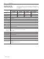
StrataScan Bar Code
Reader Specifications
The following table provides the specifications for the StrataScan
Bar Code Readers (Catalog Nos. 2755-LHR-5B, 2755-LHR-3C, and
2755-LHR-5C).
Specification
Description
Catalog No.
2755-LHR-5B
Catalog No.
2755-LHR-3C
Catalog No.
2755-LHR-5C
Scan Speed
5250 scan lines per
second
3360 scan lines per
second
5600 scan lines per
second
7350 scan lines per
second
Number of Scan Lines
75 interlocking lines
48 interlocking lines
80 interlocking lines
80 interlocking lines
Operating Current
2.5 A
2.8 A
3.59 A
3.59 A
Power Requirements
Input + 12V dc ± 4% regulated @ 480 mA with 200 mV p–p maximum ripple
Scan Pattern
Omnidirectional
Tilt
360
Skew Tolerance
± 60
Pitch Angle
± 60
Decode Depth of Field
36 in. to 76 in. (91 cm to 193 cm)
Minimum Element
Width
Refer to StrataScan Bar Code Readers User Manual, Pub. No. 2755-6.13
Print Contrast Minimum
35% reflectance difference
Output Wavelength
675 nm nominal
Ambient Light Immunity
Artificial Lighting
400 ft candles (fluorescent, incandescent, and mercury vapor)
Soft Outdoor
1800 ft candles
Housing Rating
NEMA 12 steel case
Operating Shock
100g for 1 ms
Electrostatic Discharge
15 kv IEC 801-2 level 4
Operating Temperature
32F to 104F (0C to 40C)
Storage Temperature
–40F to 140F (–40C to 60C)
Humidity
5% to 95% noncondensing
CDRH Class
II
Agency Certification
•cUL listed
•UL listed
•CE marked for all applicable directives.
•IEC class I
Publication 2755-6.13
Catalog No.
2755–LHR–5BX1
Specifications
A–3
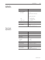
Interface Box
Specifications
Description
Catalog Number
Specification
2755-LHB-1
Electrical Characteristics
Input Voltage
UL and cUL
100, 115, or 230V ac at 50 Hz, 60 Hz
6.1 A
CE
115, 230V ac at 50 Hz, 60 Hz
5.1A
Relay
Triac, 5 A EEA Countries
6 A USA and Canada
Output for Sensor
+12V dc @ 200 mA
Operating Temperature
32F to 122F (0C to 50C)
Humidity
5% to 95% noncondensing
Agency Certification
• cUL listed
• UL listed
• CE marked for all applicable directives.
Power Supply
Specifications
Description
Specification
Replacement Part Number
77126–896–01
Input Voltage
100 to 240V ac
Input Frequency
50 to 60 Hz
Output Voltage
+12 V
Vibration
Acceleration
± 7.35 m/sec2
Direction
x, y, and z axis
Operating Temperature
41F to 113F (5C to 45C)
Storage Temperature
-13F to 185F (-25C to 85C)
Operating Humidity
20%-80% non–condensing
Storage Humidity
5%-90% non–condensing
Agency Certification
• CSA certified
• UL Recognized
• CE marked for all applicable directives
Publication 2755-6.13
A–4
Specifications
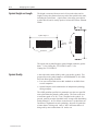
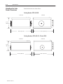
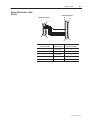
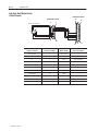
StrataScan Bar Code
Reader Dimensions
Reader dimensions are shown below:
Catalog Number 2755-LHR-5B
Front View
Side View
5.75 in.
(14.6 cm)
11.45 in. (29.1 cm)
11.12 in. (28.2 cm)
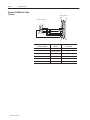
Catalog Numbers 2755-LHR-3C, -5C and -5BX1
Front View
Side View
7.25 in.
(18.4 cm)
15.19 in. (38.6 cm)
Publication 2755-6.13
14.31 in. (36.3 cm)
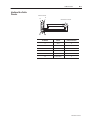
Specifications
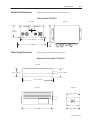
Interface Box Dimensions
A–5
Dimensions for the interface box are shown below:
Catalog Number 2755-LHB-1
Front View
Top View
3.25 in.
(8.26 cm)
6.0 in. (15.24 cm)
5.31 in.
(13.48 cm)
7.4 in. (18.89 cm)
Power Supply Dimensions
Power supply dimensions are shown below:
Replacement Part Number 77126-896-01
Front View
1.50 in. (3.81 cm)
1.59 in. (4.04 cm)
5.73 in. (14.55 cm)
Top View
Side View
2.54 in. (6.45 cm)
5.77 in. (14.66 cm)
2.50 in. (6.35 cm)
Publication 2755-6.13
A–6
Specifications
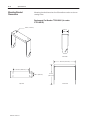
Mounting Bracket
Dimensions
Mounting bracket dimensions for all StrataScan readers are shown
starting below:
Replacement Part Number 77126-898-01 (for reader
2755-LHR-5B)
0.41 in. (1.04 cm)
3.25 in.
(8.26 cm)
Side View
11.00 in. (27.94 cm)
8.25 in. (20.96 cm)
1.50 in. (3.81 cm)
Top View
Publication 2755-6.13
9.75 in.
(24.77 cm)
Front View
Specifications
A–7
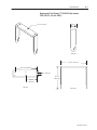
Replacement Part Number 77126-898-02 (for readers
2755-LHR-3C, -5C and -5BX1)
3.25 in.
0.41 in. (1.04 cm)
(8.26 cm)
Side View
14.75 in. (37.47 cm)
12.00 in. (30.48 cm)
1.50 in. (3.81 cm)
11.19 in.
(28.42 cm)
6.00 in.
(15.24 cm)
Top View
Front View
Publication 2755-6.13
Cable Pinouts
This appendix provides the cable pinouts for the readers, interface
box, power supply, and assorted cables.
Publication 2755-6.13
B–2
Cable Pinouts
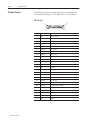
Reader Pinouts
The following sections provide the pinouts for the StrataScan Bar
Code Readers (Catalog Nos. 2755-LHR-5B,-3C, -5C and 5BX1).
RS-232 Port
1
13
14
Pin
Publication 2755-6.13
25
Signal
Function
1
GND
Chassis ground
2
RXD
Reader receives data from the host device.
3
TXD
Reader transmits data to the host device.
4
CTS Input
Reader is requesting data from the host device.
5
RTS Output
Host device is requesting data from the reader.
6
Not Used
Pin not used.
7
GND
Signal ground
8
Not used
Pin not used.
9
RXB–
Reader receives data from the host device (RS-422).
10
RXA+
Reader receives data from the host device (RS-422).
11
TXY+
Host transmit data to the reader (RS-422).
12
TXZ–
Host transmit data to the reader (RS-422).
13
GND
Ground
14
GND
Ground
15
Not Used
Pin not used.
16
Not Used
Pin not used.
17
Not Used
Pin not used.
18
Not Used
Pin not used.
19
Not Used
Pin not used.
20
DTR Input
The data terminal is ready.
21
Not Used
Pin not used.
22
Not Used
Ground
23
Not Used
Pin not used.
24
Not Used
Pin not used.
25
GND
Ground
Cable Pinouts
B–3
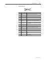
Interface Box Port
1
8
9
Pin
15
Signal
Function
1
RXD
Reader receives data from the interface box.
2
CTS
Reader is requesting data from the interface box.
3
Not Used
Pin not used.
4
Not Used
Pin not used.
5
Triac+
Controls the triac input.
6
Sensor+
Pin that provides the sensor’s object detected input
signal.
7
Sensor Alarm+
Pin that provides the sensor’s optional marginal sensing
alarm input signal.
8
Not Used
Pin not used.
9
TXD
Reader transmit data to the interface box.
10
RTS
Interface box is requesting data from the reader.
11
GND
Signal ground
12
Not used
Pin not used.
13
Triac–
Controls the triac input.
14
Sensor–
Pin that provides the sensor’s object detected input
signal.
15
Sensor Alarm–
Pin that provides the sensor’s optional marginal sensing
alarm input signal.
Publication 2755-6.13
B–4
Cable Pinouts
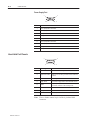
Power Supply Port
1
5
6
9
Pin
Function
1
12V dc input power to the reader.
2
12V dc input power to the reader.
3
Earth ground
4
Power ground
5
Power ground
6
12V dc input power to the reader.
7
12V dc input power to the reader.
8
Power ground
9
Power ground
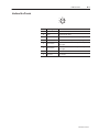
Hand–Held Port Pinouts
1
5
6
Pin
Signal
9
Function
1
Start of Scan
Synchronizes decode logic with the scanner.
2
Digitized Bar Pattern
Input receives a series of pulses proportional to the
widths of bar code being scanned from the hand-held
scanner.
3
Decode LED
Controls green decode LED on hand-held scanner.
5
Trigger Switch
Connected to trigger switch of the hand-held scanner
6
Enable
Signal output to power up the hand-held scanner, turn
on the laser, and turn on the scanning motor.
7
Ground
8
Shield ground
9
Power
+5V dc to power hand-held scanner
Note: Place a female contact in pin 4 of the 9–pin hand–held
connector.
Publication 2755-6.13
Cable Pinouts
B–5
Interface Box Pinouts
G
H
A
B
F
E
C
D
Pin
Signal
Function
A
Triac+
Controls the triac input.
B
Triac–
Controls the triac input.
C
Sensor+
Provides the sensor’s object detected input signal.
D
Sensor–
Provides the sensor’s object detected input signal.
E
Sensor Alarm
Provides the sensor’s optional marginal sensing alarm
input signal.
F
Sensor Alarm
Provides the sensor’s optional marginal sensing alarm
input signal.
G
Not Used
Pin not used.
H
Not Used
Pin not used.
Publication 2755-6.13
B–6
Cable Pinouts
Power Supply Pinouts
1
5
6
9
Pin
Publication 2755-6.13
Function
1
12V dc input power to the reader.
2
12V dc input power to the reader.
3
Earth ground
4
Power ground
5
Power ground
6
12V dc input power to the reader.
7
12V dc input power to the reader.
8
Power ground
9
Power ground
Cable Pinouts
Reader Master/slave Cable
Pinouts
B–7
Slave Reader Connector
Master Reader Connector
13
25
1
9
15
8
1
14
Master Reader Connector
(15-Pin) Pin Number
Signal from
Master Reader
Slave Reader Connector
(25-Pin) Pin Number
1
RXD (input)
3
2
CTS (output)
4
9
TXD (output)
2
10
RTS (input)
5
11
GND
7
Publication 2755-6.13
B–8
Cable Pinouts
Reader Null Modem Cable
Pinouts
Reader Connector
13
PC or PLC Connector
25
1
6
9
5
1
Publication 2755-6.13
14
PC or PLC Connector
(9-Pin) Pin Number
Signal from
Reader
Reader Connector (25-Pin)
Pin Number
3
RS-232 Receive
2
2
RS-232 Transmit
3
7
CTS (input)
4
8
RTS (output)
5
5
GND
7
4
DTR (input)
20
Cable Pinouts
Interface Box Cable
Pinouts
B–9
Reader Connector
9
1
Interface Box Connector
A
H
G
F
B
C
E
D
15
8
Reader Connector (15-Pin)
Pin Number
Signal from
Reader
Interface Box Connector
(8-Pin) Pin Number
5
Triac+
A
13
Triac–
B
6
Sensor+
C
14
Sensor–
D
7
Sensor alarm+
E
15
Sensor alarm–
F
Publication 2755-6.13
B–10
Cable Pinouts
Interface Box Master/slave
Cable Pinouts
Slave Reader Connector
Master Reader Connector
9
Interface Box Connector
H
A
13
25
1
G
F
B
C
E
D
15
8
14
1
Publication 2755-6.13
Interface Box Connector
(8-Pin) Pin Number
Master Reader Connector
(15-Pin) Pin Number
Signal from
Master Reader
Slave Reader Connector
(25-Pin) Pin Number
No connection
1
RXD (input)
3
No connection
2
CTS (output)
4
A
5
Triac+
No connection
C
6
Sensor+
No connection
E
7
Sensor alarm+
No connection
No connection
9
TXD (output)
2
No connection
10
RTS (input)
5
No connection
11
GND
7
B
13
Triac–
No connection
D
14
Sensor–
No connection
F
15
Sensor alarm–
No connection
European Union Directives
This appendix provides information regarding:
• compliance to European Union Directives
• declaration of conformity
Compliance to European
Union Directives
If this product has the CE mark, it meets applicable standards
required for installation within the European Union and EEA
regions. It has been designed and tested to meet the following
directives.
This product is tested to meet Council Directive 89/336/EEC
Electromagnetic Compatibility (EMC) and the following standards,
in whole or in part, documented in a technical construction file:
• EN 50081-2
EMC – Generic Emission Standard, Part 2 – Industrial
Environment
• EN 50082-2
EMC – Generic Immunity Standard, Part 2 – Industrial
Environment
This product is intended for use in an industrial environment.
Low Voltage Directive
This product is tested to meet Council Directive 73/23/EEC
Low Voltage, by applying the safety requirements of EN 61131–2
Programmable Controllers, Part 2 – Equipment Requirements and
Tests.
For specific information required by EN 61131-2, see the appropriate
sections in this publication, as well as the following Allen-Bradley
publications:
• Industrial Automation Wiring and Grounding Guidelines For
Noise Immunity, publication 1770-4.1
• Guidelines for Handling Lithium Batteries, publication AG-5.4
• Automation Systems Catalog, publication B111
Publication 2755-6.13
C–2
European Union Directives
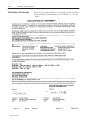
Declaration of Conformity
Publication 2755-6.13
Below is a copy of the Declaration of Conformity for the StrataScan
Bar code Readers (Catalog Numbers 2755-LHR-5B, -3C, -5C, and
-5BX1)
I–1
-,3#. /1--)5 .#"#. -'+ !,++#!0,. '/! -#.0',+ -'+ !,++#!0,. "'/0+!# $.,* $.,+0 ,$ /!++#. -'+ !,++#!0,. "'/0+!# $.,* .#"#. 0, +,0&#.
"#2'!# -'+ !,++#!0,. !!#//,.'#/ 0+"."/ 2') )# /5* ,),%'#/ . !,"# 3'"0& )'+('+% %.##+ !++,0 /!+ . !,"# !&.!0#./ #'+% ".,--#" !)#+'+% /!+ 3'+",3 ,*-)'+!# 0, 1.,-#+ +',+
'.#!0'2#/ "'/0+!#/
#..,. !,"#/ $#01.#/ .#"#. %.##+ $)/&'+% ."3.# #01.#/
'+0#.$!# ,4 ,2#.2'#3 ,),%.-&'! !++'+% '/! &,/0 &+"/&('+% -., )#*/ !,++#!0,.
-'+ -'+ -'+ -'+ +/0))'+% *,1+0'+% .!(#0 !,+0!0'+% ))#+.")#5 $,.
//'/0+!# +/0))'+% ,1. ."3.# +0#+"#" 1"'#+!# ,+0#+0/ ,$ 0&'/ +1) '+0#.$!# ,4 "'*#+/',+/ $#01.#/ -,3#. !,++#!0',+/ /#+/,. !,++#!0',+/ /-#!'$'!0',+/ ,+2#+0',+/ /#" '+ 0&'/ +1)
#!).0',+ ,$ ,+$,.*'05 #!,"'+% #/'%+'+% ,1. 5/0#* "#2'!# 0'*#,10 '+0#.$!# $,.*0 '+!,*-0' ')'05 )/#. !10',+ /5* ,) "#2'!# 1+2') )# "'*#+/',+/
'+0#.$!# ,4 *,1+0'+% .!(#0 Publication 2755–6.13
I–2
maintaining the reader, 5-1
razz tone, 5-2
manual contents, P-1
Read Range, 3-5
manual conventions, P-2
reader
accessories, 2-9
connection to second reader, 4-9,
4-12
dimensions, A-4
does not enter Program mode, 5-3
features, 2-1
introduction to, 1-1
LEDs, 2-3
maintaining, 5-1
safety information, 2-6
Scan Beam Options, 2-8
specifications, A-2
symbologies used by, 2-5
troubleshooting, 5-2
Master/slave Installation (With
Interface Box), 4-10
Master/slave Installation (Without
Interface Box), 4-8
master/slave option, 4-10
Maximum scan width, 3-5
Minimum bar code width, 3-5
mounting bracket, dimensions, A-6,
A-7
Mounting bracket installation, 4-2
mounting interface box, 4-6
reader beep, 4-3
No blinking green LED, 5-2
no inter-character delay, 5-3
No motor spin, 5-2
null modem cable connection, 4-3
Pitch, 3-4
PLC or PC to Reader, 4-2
PLC or PC to reader and interface
box, 4-4
poor communication to host, 5-2
red LED on, 4-3
Related Publications, P-2
Required Tools and Equipment, 1-1
RS232
distances, 4-2, 4-4, 4-8, 4-10
installations, 4-2
RS422
distances, 4-2, 4-4, 4-8, 4-10
installations, 4-2
Safety Information
overview, 2-6
warning label, 2-7
power connections, interface box,
4-7, 4-13
Scan Beam Options, 2-8
power supply
connection to reader, 4-3
dimensions, A-5
specifications, A-3
scan window cleaning, 5-1
Scan width, maximum, 3-5
Preface, P-1
scanner system
determining symbol height and
length , 3-2
determining symbol quality, 3-2
setup goals, 3-1
Print Quality Guideline, 3-2
scanners, specifications, A-2
power terminal block, 4-7, 4-13
scanning problems, 5-3
Quiet Zone, 3-2
Publication 2755–6.13
sensor leads, 4-5
Setup Goals, 3-1
I–3
"#$ " $ "#!"% "(" & #" "#"
#! ' &! "$( !! #!# " "(
# # !## $#( # # & ( !## %!%& $!# $!# !%" #! ""! # !$"# # !! $ " '" Publication 2755–6.13
Rockwell Automation helps its customers receive a superior return on their investment by bringing
together leading brands in industrial automation, creating a broad spectrum of easy-to-integrate
products. These are supported by local technical resources available worldwide, a global network
of system solutions providers, and the advanced technology resources of Rockwell.
Worldwide representation.
Argentina • Australia • Austria • Bahrain • Belgium • Bolivia • Brazil • Bulgaria • Canada • Chile • China, People’s Republic of • Colombia • Costa Rica • Croatia • Cyprus
Czech Republic • Denmark • Dominican Republic • Ecuador • Egypt • El Salvador • Finland • France • Germany • Ghana • Greece • Guatemala • Honduras • Hong Kong
Hungary • Iceland • India • Indonesia • Iran • Ireland • Israel • Italy • Jamaica • Japan • Jordan • Korea • Kuwait • Lebanon • Macau • Malaysia • Malta • Mexico • Morocco
The Netherlands • New Zealand • Nigeria • Norway • Oman • Pakistan • Panama • Peru • Philippines • Poland • Portugal • Puerto Rico • Qatar • Romania • Russia • Saudi
Arabia • Singapore • Slovakia • Slovenia • South Africa, Republic of • Spain • Sweden • Switzerland • Taiwan • Thailand • Trinidad • Tunisia • Turkey • United Arab Emirates
United Kingdom • United States • Uruguay • Venezuela
Rockwell Automation Headquarters, 1201 South Second Street, Milwaukee, WI 53204-2496 USA, Tel: (1) 414 382-2000 Fax: (1) 414 382-4444
Rockwell Automation European Headquarters, Avenue Hermann Debroux, 46, 1160 Brussels, Belgium, Tel: (32) 2 663 06 00, Fax: (32) 2 663 06 40
Rockwell Automation Asia Pacific Headquarters, 27/F Citicorp Centre, 18 Whitfield Road, Causeway Bay, Hong Kong, Tel: (852) 2887 4788, Fax: (852) 2508 1846
World Wide Web: http://www.ab.com
Publication 2755-6.13 — November 1997
PN 40062-389-01 (A)
Copyright 1997 Rockwell International
All rights
reserved. Printed
PublicationCorporation.
2755-6.13
— November
1997in USA