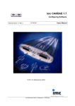
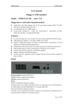
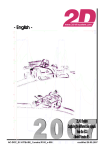
1
1 :4 2 .6 0
0
0
0
25
2500
50
25
75
5000
100
7500
50
125
150
10000
75
175
200
12500
100
225
rpm
%
k m /h
Start
3:52.5
3:55.0
3:57.5
4:00.0
4:02.5
Art.No.: AC-DOC_SY-KIT-SensorOptions_08-000
4:05.0
4:07.5
4:10.0
t
modified 01.04.2009
Table of content
Table of content ......................................................................................................................................................... 2
Preface ...................................................................................................................................................................... 3
SYMBOLS USED IN THE TEXT ...................................................................................................................3
1. Basic information of all modules and their features ............................................................................................... 4
2. Available sensor options........................................................................................................................................ 5
2.1 MOUNTING THE DIFFERENT SENSORS ................................................................................................5
2.1.1 Mounting the front suspension sensor...................................................................................................... 5
2.1.2 Mounting the rear suspension sensor ...................................................................................................... 6
2.1.3 Mounting the brake pressure sensor ........................................................................................................ 7
2.2 CONNECTING THE DIFFERENT SENSORS .............................................................................................8
2.2.1 Connecting the front suspension sensor................................................................................................... 8
2.2.2 Connecting the rear suspension sensor.................................................................................................... 8
2.2.3 Connecting the brake pressure sensor ..................................................................................................... 9
2.2.4 Connecting the 2D Laptime receiver ..................................................................................................... 10
AC-DOC_SY-KIT-SensorOptions_08-000
page 2 / 13
Preface
This documentation contains the necessary information to setup and to work with the 2D kit system.
In order to achieve the optimum result when working with the 2D-Kit System, we recommend to read
the instructions carefully and follow them step by step.
Symbols used in the text
In the paragraphs highlighted with this symbol, you will find tips and practical advice to
work with the 2D-Kit System.
In the paragraphs highlighted with this symbol, you will find additional information and it is
very important that you follow the instructions given.
Documentation reference
ð The user get an unique item number for an user manual to find further assistance
Additional information about manuals, datasheets, software updates or new calculation
files can be downloaded from our homepage. The specific download area for the Kit
system can be found at: http://www.2d-kit-system.com (=>See Downloads)
Basic Kit
Sensor options
A/F (lambda) add-on Kit (4-stroke) with 1CH or 2CH
Deto add-on Kit (2-stroke)
Possible Updates
Kit software user manual (delivered with the CD: SW-CD RaceKIT)
2D Debus & Diebold
Meßsysteme GmbH
Alte Karlsruher Straße 8
76227 Karlsruhe
Tel.: +49(0)721 94485-0
Fax: +49(0)721 94485-29
EMAIL:
[email protected]
Homepage: http://www.2D-Datarecording.com
Homepage: http://www.2D-Kit-System.com
AC-DOC_SY-KIT-SensorOptions_08-000
page 3 / 13
1. Basic information of all modules and their features
SY-KITSusp_Bike-000: KIT suspension sensor add on:
This sensor package expands the system for full chassis
recording so good balance and drivability are no longer
miracles. This sensor Kit comes with a 150mm and 75mm
high end suspension travel sensor. This sensor kit allows
to analysing suspension travel and damper speed to set up
your bike suspension.
SY-KITPBrake-000: KIT brake pressure add on:
Very small and lightweight 100 bar pressure sensor to
measure front brake usage. The Sensor comes with an
adapter for easy fitting to the bike brake system. For proper
suspension setup, the brake pressure sensor is a MUST,
as braking influences the front fork setting most.
SY-KITSens_race-000: KIT sensor add on:
Special Sensor package for racing application.
Unlike the KITSusp_Bike and KITPBrake equivalents the
sensors are not connected directly to the data logger but to
a small, separate connection box. Connection and
exchange of sensors is simplified.
This package includes a 150mm and a 75mm high-end
suspension travel sensor, 1 small and lightweight brake
pressure sensor and a Box mini for the connection. This
sensor kit allows analyzing suspension travel, damper
speed and brake pressure to set up your bike suspension
more properly.
SY-KIT_LR05-000: KIT Laptime Receiver:
For higher precission in Laptime compared to the GPS
Laptimeing the IR Laptrigger receiver is available. This
receiver will provide 0.0025 sec accuracy in Laptime.
AC-DOC_SY-KIT_IR-Laptriggerset-000
AC-KIT_LT05-000: Laptrigger transmitter KIT System:
One IR Transmitter is needed on the Pit wall if you use the
IR Laptrigger receiver.
Only one IR Transmitter is needed per Racetrack.
AC-DOC_SY-KIT_IR-Laptriggerset-000
AC-DOC_SY-KIT-SensorOptions_08-000
page 4 / 13
2. Available sensor options
2.1 Mounting the different sensors
2.1.1 Mounting the front suspension sensor
The potentiometer has to be fitted parallel to the tubes of the fork to give correct values.
The maximum measure range of the used sensor must be equal or even longer than your
maximum suspension travel (150mm range is usual for front fork).
The picture above shows a clamp which is designed as a folding ring and offers an easy and parallel
sensor support mounting.
Please check very carefully that neither the sensor nor the supports will limit the steering
angle or might get caught by any cable or line or damage them !!
AC-DOC_SY-KIT-SensorOptions_08-000
page 5 / 13
2.1.2 Mounting the rear suspension sensor
To measure the suspension travel of the rear wing in some cases (for example R6) it is
impossible to mount the sensor directly parallel to the (standard) shock. So you have to
put it somewhere between the rear frame and the wing. This causes big differences of
usable sensor measure length depending on the location of the of mounting. (50 mm or
75mm will work in most cases)
To avoid water entering the housing, please mount the grinder bar down below !
View of the rear suspension sensor (linear potentiometer 75mm),
example mounted at a Yamaha R1
Also in this case please check very carefully that neither the sensor nor the supports
touch any moving parts or might block them. Check for maximal and minimal travel !
AC-DOC_SY-KIT-SensorOptions_08-000
page 6 / 13
2.1.3 Mounting the brake pressure sensor
The picture below shows a possibility to fix the pressure sensor to the brake line system.
For this a special mounting kit is included in the sensor add-on kit, which fixes the
pressure sensor with a double hollow screw to the main brake cylinder.
AC-DOC_SY-KIT-SensorOptions_08-000
page 7 / 13
2.2 Connecting the different sensors
2.2.1 Connecting the front suspension sensor
The wires of both suspension sensors are delivered by 2D with the “Tyco contact” pins already
crimped. Just insert the individual contacts into the 34pin AMP connector. The following table gives
you the correct positions for the pins.
Technical information
Cable length:
Crimp contacts:
Susp_Front (white)
AGND (black)
+5V (red)
Interface unit (34pin AMP connector)
600mm (isolated) + 40mm (stripped PUR-cable)
“Tyco crimp contacts”
Pin 10
Pin 18
Pin 26
>> see appendix
>> see appendix
>> see appendix
2.2.2 Connecting the rear suspension sensor
Technical information
Cable length:
Crimp contacts:
Susp_Rear (white)
AGND (black)
+5V (red)
Interface unit (34pin AMP connector)
1200mm (isolated) + 40mm (stripped PUR-cable)
“Tyco crimp contacts”
Pin 11
Pin 19
Pin 27
AC-DOC_SY-KIT-SensorOptions_08-000
>> see appendix
>> see appendix
>> see appendix
page 8 / 13
2.2.3 Connecting the brake pressure sensor
The wires of the brake pressure sensor are delivered from 2D with the “Tyco contact pins” already
crimped. Just insert the individual contacts into the 34pin AMP connector. The following table gives
you the correct positions for the pins.
Technical information
Cable length:
Crimp contacts:
Brake pressure (white)
AGND (black)
+12V (red)
Interface unit (34pin AMP connector)
500mm (isolated) + 40mm (stripped PUR-cable)
“Tyco crimp contacts”
Pin 4
Pin 21
Pin 30
AC-DOC_SY-KIT-SensorOptions_08-000
>> see appendix
>> see appendix
>> see appendix
page 9 / 13
2.2.4 Connecting the 2D Laptime receiver
The wires of the laptime receiver are delivered by 2D with the “Tyco contact pins” already crimped.
Just insert the individual contacts into the 34pin AMP connector. The following table gives you the
correct positions for the pins.
Technical information
Cable length:
Crimp contacts:
Signal
(white)
DGND
(black)
+12V
(red)
Interface unit (34pin AMP connector)
500mm (isolated) + 40mm (stripped PUR-cable)
“Tyco crimp contacts”
Pin 14
Pin 22
Pin 31
>> see appendix
>> see appendix
>> see appendix
You will get a start-up reference for the IR laptrigger set (transmitter + receiver) at the 2D
KIT system website located in the download area. Take a look at
AC-DOC_SY-KIT_IR-Laptriggerset-000
AC-DOC_SY-KIT-SensorOptions_08-000
page 10 / 13
Required for:
SY-KITSusp_Bike-000: KIT suspension sensor add on
SY-KITSens_race-000: KIT sensor add on
AC-DOC_SY-KIT-SensorOptions_08-000
page 11 / 13
Required for:
SY-KITPBrake-000 : KIT brake pressure sensor add on
SY-KITSens_race-000: KIT sensor add on
AC-DOC_SY-KIT-SensorOptions_08-000
page 12 / 13
Required for:
SY-KITLR05-000: KIT Laptime Receiver
AC-DOC_SY-KIT-SensorOptions_08-000
page 13 / 13