1
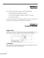
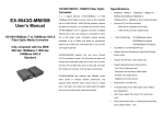
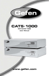
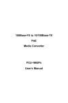
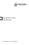
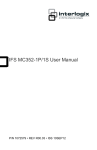
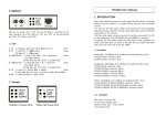
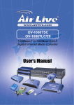
Copyright Copyright © PLANET Technology Corp. 2004. Contents subject to revision without prior notice. PLANET is a registered trademark of PLANET Technology Corp. The information in this manual is subject to change without notice. All other trademarks belong to their respective owners. Disclaimer PLANET Technology does not warrant that the hardware will work properly in all environments and applications, and makes no warranty and representation, either implied or expressed, with respect to the quality, performance, merchantability, or fitness for a particular purpose. PLANET has made every effort to ensure that this User’s Manual is accurate; PLANET disclaims liability for any inaccuracies or omissions that may have occurred. Information in this User’s Manual is subject to change without notice and does not represent a commitment on the part of PLANET. PLANET assumes no responsibility for any inaccuracies that may be contained in this User’s Manual. PLANET makes no commitment to update or keep current the information in this User’s Manual, and reserves the right to make improvements to this User’s Manual and/or to the products described in this User’s Manual, at any time without notice. If you find information in this manual that is incorrect, misleading, or incomplete, we would appreciate your comments and suggestions. FCC Warning This equipment has been tested and found to comply with the regulations for a Class A digital device, pursuant to Part 15 of the FCC Rules. These limits are designed to provide reasonable protection against harmful interference when the equipment is operated in a commercial environment. This equipment generates, uses, and can radiate radio frequency energy and, if not installed and used in accordance with this user’s guide, may cause harmful interference to radio communications. Operation of this equipment in a residential area is likely to cause harmful interference, in which case the user will be required to correct the interference at his own expense.CE mark Warning This is a Class A product. In a domestic environment, this product may cause radio interference, in which case the user may be required to take adequate measures. CE Mark Warning This is a Class A product. In a domestic environment, this product may cause radio interference, in which case the user may be required to take adequate measures. Revision User’s manual for PLANET Fast Ethernet Converter Multi-mode: FT-801, FT-802, FT-803 Single-mode: FT-802S15, FT-802S35, FT-802S50, FT-806A20, FT-806B20 Rev 6.0 (September. 2004) Part No. 2010-000002-005 Table of Contents Chapter 1 Overview 1 Chapter 2 Model List 1 Chapter 3 Checklist 2 Chapter 4 Product Outlook 2 Chapter 5 Link Fault Pass through (LFP) 3 Chapter 6 Installing the Converter 6 Chapter 7 Duplex Mode setting 7 Chapter 8 LED indication 8 Chapter 9 Cable Connection Parameter 9 Chapter 10 FT-80X Technical Specifications 10 Chapter 11 Power information 11 Chapter 1 Overview Thank you for purchasing PLANET FT-80X family 10/100Mbps Ethernet Twisted pair to 100Base-FX Fiber-optic Bridge Converter. This converter is used to convert one type media signal to other type equivalent that allows two type segments connect easily, efficiently and inexpensively. This converter can be used as a standalone unit or as a slide-in module to the 10”/19” media chassis (up to 15 units) for a TP and Fiber combined networks at a central wiring closet. Please contact with your sales representative for more about the 19” media chassis. Chapter 2 Model List Your Fast Ethernet Converter comes with one of the following models. ð FT-801: on board ST fiber connector ð FT-802/S: on board SC fiber connector ð FT-803: on board MTRJ fiber connector ð FT-806A20: on board single SC fiber connector ð FT-806B20: on board single SC fiber connector Models with last character “S” indicate the fiber-port is with “Single-Mode” optic fiber connector and followed with a number indicates the maximum wiring distance. In the following sections, the term “FT-80X” indicates the product family above. 1 Chapter 3 Checklist Your FT-80X carton should contain the following items: ð The Fast Ethernet Bridge Converter ð AC-DC Power Adapter (Output: 5VDC, 2 A max.) ð This user’s manual If any item is missing or damaged, please consult the dealer from whom you purchased your Fast Ethernet Converter. Chapter 4 Product Outlook Right View There are one RJ-45 Twisted-Pair jack (Auto-MDI/MDI-X), one fiber-optic connector (vary by model) and six LED indicators. Left View One DIP switch for Fiber-optic operating mode selection, FDX for full-duplex, and HDX for half-duplex. 2 Side View (FT-80X) One DIP switch for Link Fault Pass Through (LFP) feature, “ON” to turn-on the LLCF and LLR detection. And “OFF” to turn–off this feature. Please refer to the following sections for more. DIP Switch for LFP function. Chapter 5 Link Fault Pass through (LFP) The LFP function includes the Link Fault Pass Through function (LLCF/LLR) and the DIP Switch design. LLCF/LLR can immediately alarm administrators the problem of the link media and provide efficient solution to monitor the net. The DIP Switch provides disable or enable the LFP function. LLCF (Link Loss Carry Forward) means when a device connected to the converter and the TP line loss the link, the converter’s fiber will disconnect the link of transmit. LLR (Link Loss Return) means when a device connected to the converter and the fiber line loss the link, the converter’s fiber will disconnect the link of transmit. Both can immediately alarm administrators the problem of the link media and provide efficient solution to monitor the net. 3 Link Loss Carry Forward (LLCF) FT-80X incorporates an LLCF function for troubleshooting a remote connection. When LFP function is enabled, the FL/TP ports do not transmit a link signal until they receive a link signal from the opposite port. The diagram below shows a typical network configuration with a good link status using FT-80X for remote connectivity. If the connection breaks, FT-80X that link loss forward to the switch/hub that generates a trap to the management station. The administrator can then determine the source of the problem. *Units are shipped with the LFP function enabled (ON). Link Loss Return (LLR) The fiber ports of FT-80X have been designed with an LLR function for troubleshooting a remote connection. LLR works in conjunction with LLCF. When LFP function is enabled *(by default), the port’s transmitter shuts down when its receiver fails to detect a valid receive link. LLR should only be enabled on one end of the link and is typically enabled on either the unmanaged or remote device. The diagram below shows a typical network configuration with a good link status using FT-80X for remote connectivity. Note that LLR and LLCF are enabled as indicated in the diagram. 4 If one of the optical conductors is bad (as shown in the diagram box below), the converter with LLR function will return a no-link condition to its link partner. With LLCF function also enabled, the no-link condition is carried forward to the switch/hub where a trap is generated to the management station, and the administrator can then determine the source of the loss. NOTE: LFP function is turn-on in default. This feature can also be turned off via the side DIP-switch. If you are familiar with the network installation and for diagnostic purpose (i.e. check which end is broken), you can turn it off and reset the converter to make it take effect. Otherwise, please remains it in the default position. 5 Chapter 6 Installing the Converter Please follow these steps to install the converter: • Turn off the power of the device/station in a network to which the FT-80X will be attached • Ensure that there is no activity in the network • Attach fiber cable from the FT-80X to the fiber network. TX, RX must be paired at both ends • Attach a Cat. 5 UTP cable from the 10/100Base-TX network to the RJ-45 port on the FT-80X. • Connect the 5VDC power adapter to the FT-80X and verify that the Power LED lights up. • Turn on the power of the device/station, the TX Link and FX Link LEDs should light when all cables are attached • Turn on the power of the device/station, the TX Link and FX Link LEDs should light when all cables are attached • RJ-45/STP, UTP Cat 5, straight/crossover cable is accepted NOTE: 6 • Please refer to section 8 for more about the wiring distance of your TP, Optic-fiber networks. Chapter 7 Duplex Mode setting The TP port of FT-80X supports duplex mode detection by autonegotiation (A-N). The following is the duplex mode parameters: Fast Ethernet Device FT-80X Duplex Mode support Ethernet / Fast Ethernet Hub Half-Duplex Ethernet / Fast Ethernet Switch Half-Duplex (without A-N) Fast Ethernet Devices * Full-Duplex / Half- Support Auto-Negotiation Duplex NOTE: Normally, an A-N switch will detect and set to full-duplex, where a dual-speed hub will detects half. There is a DIP-switch as in the left view as section 4. Please check and follow the duplex mode of the fiber device and have the duplex selection to your FT-80X. 7 Chapter 8 LED indication LED Color Description FX LNK Green Blinks: when any FX packets transmit- / ACT ting and receiving Lit: when Fiber connection is good TX LNK Green / ACT Blinks: when any TP packets transmitting and receiving Lit: when TP connection is good FX FDX/ Green COL Lit: when Full-duplex mode is enabled in FX port Blinks: indicate that the connection is experiencing collisions. TX FDX/ Green COL Lit: when Full-duplex mode is enabled (detect by Auto-Negotiation) in TP port Blinks: indicate that the connection is experiencing collisions. 100 Green Lit when the TP port runs in 100Mbps. Remains off while LINK LED lit represent the TP port runs in 10Mbps PWR Green Lit when +5VDC power detected Fiber-optic Partner should be set to the cor- NOTE: 8 rect mode according to this FDX indicator for optimal network performance. Chapter 9 Cable Connection Parameter The limitations are as below: Duplex Connection Limitation (max.) Twisted Pair Half / Full Node to Node Node to Switch/Hub 100 meters Multi-Mode Converters MM Half MM Full Node to Node Node to Switch Node to Node Node to Switch 412 meters 2 kilometers Single-Mode Converters* (FT-80xynn; x= 2, 6; y= S, A, B; nn=km) SM Full Node to Node Node to Switch Depends on model 1. Consult your local dealer for more about our single mode fiber connectivity. NOTE: 2. A model (TX: 1310nm; RX: 1510nm) and B model (TX: 1510nm; RX: 1310nm) should runs in pair. 9 Chapter 10 FT-80X Technical Specifications The FT-80X comes with the following standard features: · Standard: IEEE802.3/u, 10/100Base-TX and 100BaseFX · Connectors: ð One RJ-45 (Auto-MDI/MDI-X) Twisted Pair, EIA568 ð One Fiber-optic, 1310nm wavelength (except: FT806A/FT-806B), connector-type vary with model · Data Transfer Rate: 10/100Mbps (TP), 100Mbps (FX) · Duplex mode support: Full or half-duplex mode by Auto-Negotiation (TP) · LED indicators: PWR, FX LNK/ACT, FX FDX/COL TP 100, TP LNK/ACT, TP FDX/COL · Power Requirement: 5V DC, 2A · Ambient Temperature: 0° to 50°C (operating) · Humidity: 5% to 90% (non-condensing) · Dimension: 26 x 70 x 97mm (HxWxD) · Cable: ð UTP: Cat 5 UTP cable ð Fiber: MM: 50/125 µm or 62.5/125 µm optic fiber ð Fiber: SM: 8.3/125, 8.7/125, 9/125 µm optic fiber Connecting to Router, Bridge, or Switch, Hub, please refer to the device’s Technical Manual. 10 Chapter 11 Power information The power jack of FT-80X is with 2.5mm in the central post and required +5VDC power input. It will conform to the bundled ACDC adapter and Planet’s Media Chassis. Should you have the problem to make the power connection, please contact your local sales representative. Please keep the AC-DC adapter as spare parts when your FT-80X is installed to a Media Chassis. 11 This page is intentionally left blank 12 2010-000002-005