1
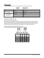
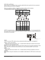
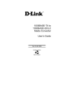
OV-1000TSC
OV-1000TLC/20
1000Base-T to 1000Base-SX/LX
Gigabit Ethernet Media Converter
User’s Manual
FCC Class B Certification
This equipment has been tested and found to comply with the regulations for a Class B
digital device, pursuant to Part 15 of the FCC Rules. These limits are designed to provide
reasonable protection against harmful interference when the equipment is operated in a
commercial environment. This equipment generates, uses, and can radiate radio
frequency energy and, if not installed and used in accordance with this user’s guide, may
cause harmful interference to radio communications. Operation of this equipment in a
residential area is likely to cause harmful interference, in which case the user will be
required to correct the interference at his own expense.
CE Mark Warning
This is a Class B product. In a domestic environment, this product may cause radio
interference, in which case the user may be required to take adequate measures.
VCCI Class B Compliance (Japan)
This is a product of VCCI Class B Compliance
AirLive OV-1000 User’s Manual
Table of Contents
INTRODUCTION ........................................................................................................................................................... 1
ABOUT MEDIA CONVERTER.................................................................................................................................... 1
PRODUCT FEATURES ................................................................................................................................................. 1
INSTALLATION............................................................................................................................................................. 1
SELECTING A SITE FOR THE EQUIPMENT.......................................................................................................... 1
CONNECTING TO POWER ................................................................................................................................................ 2
INSTALLING IN A CHASSIS (OV-MCR116) ..................................................................................................................... 2
MONITORING THE CONVERTER THROUGH MANAGEMENT MODULE ............................................................................... 2
LED INDICATOR........................................................................................................................................................... 3
LINK PASS THROUGH FUNCTION .................................................................................................................................... 3
SWITCH .......................................................................................................................................................................... 4
SPECIFICATIONS ......................................................................................................................................................... 5
i
AirLive OV-1000 User’s Manual
Introduction
Thank you for choosing the 1000Base Gigabit Ethernet Media Converter, The Converter
introduced here provides one channel media conversion between 1000BASE-TX and
1000BASE-SX/LX.
About Media Converter
Media Converter is a network technology specified by IEEE 802.3ab and IEEE 802.3z
1000BASE-TX and 1000BASE-SX/LX standards.
Product Features
9
9
9
9
9
9
9
9
9
One-channel media conversion between 1000BASE-TX and 1000BASE-SX/LX
Fiber media allows: multi-mode fiber and single-mode fiber using SC connector
Link Pass Through function
Auto negotiation of duplex mode on TX port
Auto MDI/MDI-X for TX port
Full wire-speed forwarding rate
Front panel status LEDs
Used as a stand-alone device or with a chassis
Hot-swappable when used with a chassis
Installation
This chapter gives step-by-step installation instructions for the Converter.
Selecting a Site for the Equipment
As with any electric device, you should place the equipment where it will not be subjected
to extreme temperatures, humidity, or electromagnetic interference. Specifically, the site
you select should meet the following requirements:
1. The ambient temperature should be between 32 and 104 degrees Fahrenheit (0 to 40
degrees Celsius).
2. The relative humidity should be less than 90 percent, non-condensing.
3. Surrounding electrical devices should not exceed the electromagnetic field (RFC)
standards for IEC 801-3, Level 2 (3V/M) field strength.
4. Make sure that the equipment receives adequate ventilation. Do not block the
ventilation holes on each side of the switch or the fan exhaust port on the side or rear
of the equipment.
5. The power outlet should be within 1.8 meters of the switch.
1
AirLive OV-1000 User’s Manual
Connecting to Power
1.
This Converter is a plug-and-play device.
2.
Connect the supplied AC to DC power adaptor with a power voltage of 7.5Vdc/1.5Amp
to the DC-Jack on the converter, and then attach the plug into a standard AC outlet.
Installing in a Chassis (OV-MCR116)
The Converter can be fit into any of the expansion slots on a special designed chassis.
y First, install the converter onto a carrier supplied with the chassis:
Step 1- Unscrew and pull out the media converter board.
Step 2- Plug in the media board to any of the vacant slot.
Step 3- Fit the converter onto the carrier and use the screw to secure it.
Monitoring the Converter through Management Module
There is a management module that can control this media converter through the
chassis system, this media converter can be controlled through Web Browser, SNMP
and terminal emulation program.
The management module will detect the default reset on the DIP switches and display
out the status, also the management module can control the function through the
chassis system.
NOTE: To control the function in a working station, need to collocate together with
optional Chassis System and Management Module.
2
AirLive OV-1000 User’s Manual
LED Indicator
The LED indicators give you instant feedback on status of the converter:
LEDs
State
Indication
Power
Lights on
Power on
Lights off
Power off
Lights on
Linking
Lights Blinking
Data transmitting and receiving
Lights off
Not Linking
(PWR)
Link and Activity
(LINK/ACT)
Link Pass Through Function
LLCF (Link Loss Carry Forward)
When a device connected to the converter and the TP line loss the link, the converter’s
fiber will disconnect the link of transmit, so that the other ends will know that there is a
linkage error on this end. And when the Fiber line loss the link, the converter’s TP will
disconnected, and the other end will know that there is linkage problem exist.
There is a default LLCF setting on this converter.
The table below shows how LLCF function is working:
Me d ia
C o nve rte r A
Fib e r
TX RX
Me d ia
C o nve rte r B
LINK 3
LINK 2
Copper
Copper
Fib e r
TX RX
C a b le 5
C a b le 1
C a b le 3
C a b le 2
RX TX
LINK 1
LINK 4
Gig a b it Switc h
Link Status
Disconnect
Cable 1
Cable 2
Cable 3
Cable 4
Cable 5
C a b le 4
RX TX
Gig a b it Switc h
Link Link Link Link
1
2
3
4
Off
Off
On
Off
Off
On
Off
On
Off
Off
On
Off
On
Off
Off
On
Off
Off
Off
Off
3
AirLive OV-1000 User’s Manual
LLR (Link Loss Return)
When a device connected to the converter and the fiber line loss the link, the converter’s
fiber will disconnect the link of transmit.
There is a switch to enable or disable the function of the media converter.
The table below shows how LLR function is working:
Media
LLR Auto-Negotiation
Converter
A
ON
OFF
B
OFF
OFF
Me d ia
C o nve rte r A
LINK 2
Copper
Me d ia
C o nve rte r B
Fib e r
Fib e r
TX RX
TX RX
LINK 1
Copper
Ca b le 1
Ca b le 2
C a b le 3
Copper
C a b le 4
LINK 3
LINK 4
Gig a b it Switc h
Copper
Gig a b it Switc h
Link
Status
Link 1
Lin Link Link
k2 3
4
Disconn
ect
Cable 1 Off Off Off Off
Cable 2 Off On On Off
Cable 3 Off Off Off Off
Cable 4 Off Off Off Off
NOTE: If connecting two converters with LLR function in both end, it is recommended that
the monitor end converter had to turn off the LLR function, and turn on the LLR function of
the remote end converter.
12
on
on
12
Switch 1 : On -> Forced Mode
Off -> Auto Negotiation mode
Switch 2 : On -> LLR enable
Off -> LLR disable
Switch
There is a two pin DIP switch on the module which define as switch 1 and switch 2:
Switch 1: Fiber mode switch
When the switch was turned to “On”, it means that the fiber was turned to forced mode,
and “Off” for auto-negotiation mode.
Note: Be sure the opposite end is using the same setting (forced or Auto-negotiation). And
when using two converters at the same time, the two converters MUST set to forced
mode.
Switch 2: LLR
When the switch was turned to “On”, it means that the LLR was enabled and “Off” for
disabled.
Note: When using two converters, don’t enable the both device’s LLR function at the same
time.
4
AirLive OV-1000 User’s Manual
Specifications
Standards:
IEEE802.3ab 1000BASE-TX
IEEE802.3z 1000BASE-SX/LX
Data Transfer Rate: 1488000pps for 1000Mbps
Duplex Mode:
Full Duplex Mode
LED indicators:
PWR, LNK/ACT
Cable
1000BASE-T -4 pair Cat. 5, EIA/TIA-568 100-ohm screened twisted-pair (STP),
up to 100m
1000BASE-SX -62.5/125μm multi-mode fiber optic cable, up to 220m
50/125μm multi-mode fiber optic cable, up to 550m
1000BASE-LX -9/125μm single-mode fiber optic cable, up to 20km
Dimensions
L120 × W88 × H25 mm
Weight
305 g
Power
External power adaptor 7.5V 1.5A
Media Interface:
RJ-45, SC
EMI Compatiblity:
FCC Class B
CE Certification, Class B
VCCI Class B
Temperture:
Storage: -10°C ~ 70°C
Operating: 0°C ~ 40°C
Humidity:
10% ~90% non-condensing
Power Consumption: 5.5 Watts (maximum)
5
AirLive OV-1000 User’s Manual