1
HARDWARE DESCRIPTION: CONNECTING INPUTS
POWER SUPPLY:
Connect a power supply of 18V-80V DC, check the polarity of pins. A red LED
indicates the status of power supply on board.
INPUTS:
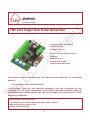
A provision for three inputs terminal IN1, IN2 and IN3 is given in stepper pulse
generator board as shown in the figure FIG:1 . All these inputs are optoisolated for noise
immunity. IN1 and IN2 are driven by external signals according to mode set in manual
mode. Terminal IN3 can be used for connecting limit, emergency switch as per the
requirement of the operator. These inputs are discussed in detail in the Auto and
Manual mode section of the manual.
CONNECTING OUTPUTS
STEP:
It is pulse output for step input of stepper drive. SPG can generate maximum 40,000
steps per second for drive.
DIR:
This output signal is fed to direction input of stepper drive.
COM:
It is the output for COM terminal of stepper drive.
POT
Three POTs are provided on the SPG board. These are used to manage the speeds
in manual mode.
MAX SPEED:
This POT adjusts the maximum speed that the motor can achieve. A provision for four
ranges of maximum speeds is given on this board. Set jumper settings for selecting
speed range and adjust POT appropiately to set required speed as maximum speed.
BASE SPEED:
This POT adjusts base or start speed at which the user wants motor to start running.
The base speed remains lesser than maximum speed.
ACCELERATION:
The acceleration range for step pulse generator is 1 to 15. Adjust acceleration by
adjusting POT. Moreover, when motion stops, motor decelerates with the same value
as the one used for ramping up/ accelerating.
6