1
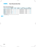
Basic Characteristics Data
Basic Characteristics Data
Model
Circuit method
Switching
frequency
[kHz]
Series/Parailel
operation
(reference)
Input
current
[A]
Inrush
current
protection
Material
Single
sided
Double
sided
Series
operation
Parailel
operation
PCB/Pattern
BRNS6
Buck Converter
600
*1
-
glass fabric base,epoxy resin
-
Multilayer
-
-
BRNS12
Buck Converter
600
*1
-
glass fabric base,epoxy resin
-
Multilayer
-
-
BRNS20
Buck Converter
600
*1
-
glass fabric base,epoxy resin
-
Multilayer
-
-
*1 Refer to Specification.
BRNS
BRNS-4
DC-DC Converters POL Type
Instruction Manual
1
Pin Connection
BRNS-6
2
Connection for Standard Use
BRNS-6
3
Wiring Input / Output Pin
BRNS-7
4
3.1
Wiring input pin
BRNS-7
3.2
Wiring output pin
BRNS-7
Function
4.1
Overcurrent protection
BRNS-8
4.2
Remote ON/OFF
BRNS-8
4.3
Remote sensing
BRNS-8
4.4
Adjustable voltage range
BRNS-8
4.5
Softstart/Start-up sequence
BRNS-9
4.6
Power good
BRNS-10
4.7
Sequence
BRNS-10
4.8
Frequency synchronization
BRNS-10
5
6
BRNS-8
Series and Parallel Operation
BRNS-11
5.1
Series operation
BRNS-11
5.2
Parallel operation
BRNS-11
Implementation-Mounting Method
BRNS-11
6.1
Mounting Method
BRNS-11
6.2
Automatic Mounting
BRNS-11
6.3
Soldering
BRNS-11
6.4
Cleaning
BRNS-11
6.5
Storage method
BRNS-11
7
Safety Considerations
BRNS-12
8
Derating
BRNS-12
8.1
9
BRNS series Derating
Package information
BRNS-12
BRNS-13
BRNS-5
BRNS
Instruction Manual
DC-DC Converters POL Type
1 Pin Connection
Table 1.1 Pin connection and function
2 Connection for Standard Use
e
sN
o
i
¡In order to use power supply,it is necessary to wire as shown in Fig
2.1.
Pin No.
BRNS
6/12
BRNS
20
BRNS
Pin Connection
Reference 3 "Wiring Input/Output Pin"
8 "Derating"
Function
RC
Remote ON/OFF
+VIN
+DC input
GND
GND(-DC input, -DC output)
+VOUT
+DC output
+S
+Remote sensing
TRM
Adjustment of output voltage
SGND
Signal GND
CLK(NC)
Clock output
SEQ
Control of Start up time and turn
PGOOD
Power good
SYNC
Input for frequency synchronization
-S
NC : BRNS6/12
-Remote sensing : BRNS20
NC
NC
NC
NC
NC
NC
NC
NC
NC
NC
¡Short the following pins to turn on the power supply.
Reference 4.3 "Remote Sensing"
¡Connect resistance to set the output voltage between TRM and
GND
Reference 4.4 "Adjustment output voltage"
¡Between input and output is not isolated.
¡The BRNS series handle only the DC input.
Avoid applying AC input directly.
It will damaged the power supply.
F1
DC
input
TRM
Ci
SGND
GND
-S
Load
RTRM
Fig.2.1 Connection for standard use
Table 2.1 External parts
No.
1
¡BRNS6/12
+S
+VOUT
+VIN
parts
Reference
F1:Fuse
3.1 (1)External fuse
2
Ci:External output capacitor
3.1 (2)External input capacitor
3
RTRM:Resistance for adjustment
output voltage
4.4 Adjustable voltage range
3 Wiring Input / Output Pin
3.1 Wiring input pin
(1) External fuse
¡BRNS20
¡Fuse is not built-in on input side. in order to protect the unit, install
the normal-blow type fuse on input side.
¡When the input voltage from a front end unit is supplied to multiple
units, install the normal-blow type fuse in each unit.
¡When the fuse is open, power good signal is not outputed.
Table 3.1 Recommended fuse
Fig.1.1 Pin Connection (Bottom View)
BRNS-6
Model
BRNS6
BRNS12
BRNS20
Rated current
15A
20A
40A
Instruction Manual
DC-DC Converters POL Type
Table 3.3 Recommended capacitor and max Co
(2) External capacitor on the input side
¡Install an external capacitor Cin, between +VIN and GND input
pins for low line-noise and for stable operation of the power supply.
Table 3.2 Recommended external input capacitor(Ceramic)
Model
BRNS6
BRNS12
BRNS20
Cin
22μF×2
22μF×2
22μF×3
No.
Model
Recommended
Max Co
1
BRNS6
47μF×1+100μF×1
1,000μF
2
BRNS12
47μF×1+100μF×1
1,000μF
3
BRNS20
100μF×2
1,000μF
¡The output ripple voltage may grow big by resonance with Co and
ESL of the wiring. If resonance frequency and switching frequency
are close.
¡Cin is within 5mm for pins. Make sure that ripple current of Cin is
less than its rating.
¡Ripple and Ripple Noise are measured, as shown in the Fig.3.4.
Cin is shown in Table3.2, Co1 and Co2 is shown in Table 3.4.
¡When an impedance and inductance level of the input line become higher, the input voltage may become unstable.
3mm
In that case, the input voltage becomes stable by increasing Cin.
+VIN
DC
input
(3) Recommendation for noise-filter
Co1 Co2
Cin
¡Install an external input filter as shown in Fig.3.1 in order to reduce conducted noise. Cin is shown in Table 3.2
GND
Load
GND
25mm
L1
F1
Oscilloscope
+VIN
Bw:20MHz
DC
input
+VOUT
C1
Ci
R
1.5m 50W
Coaxial cable
C
R=50W
C=4700pF or 10000pF
GND
Fig.3.4 Measuring method of Ripple and Ripple Noise
C1 : 100mF
L1 : 0.2mH
Table 3.4 Co1 and Co2 which is used in measuring
Fig.3.1 Example of Recommended external input filter
No.
(4) Reverse input voltage protection
1
¡Avoid the reverse polarity input voltage. It will damage the power
supply.
2
It is possible to protect the unit from the reverse input voltage by
installing an external diode as shown in Fig 3.2
3
4
5
6
+VIN
Model
BRNS6
BRNS12
BRNS20
Vo
Co1
Co2
0.6-3.3V
47μF×1
100μF×1
3.3-5.5V
22μF×1
22μF×1
0.6-3.3V
47μF×1
100μF×1
3.3-5.5V
22μF×1
22μF×2
0.6-3.3V
100μF×1
100μF×1
3.3-5.5V
22μF×2
22μF×2
DC IN
GND
Fig.3.2 Reverse input voltage protection
3.2 Wiring output pin
¡When the BRNS series supplies the pulse current for the pulse
load, please install a capacitor Co between +VOUT and GND
pins.
+ VOUT
Co
Pulse
Load
GND
Fig.3.3 wiring external output capacitor
BRNS-7
BRNS
Instruction Manual
DC-DC Converters POL Type
¡When the remote sensing function is not in use, it is necessary to
confirm that pins are shorted between +S & +VOUT and between
4 Function
-S & GND.
¡Wire between +S & +VOUT and between -S & GND as short as
possible.
4.1 Overcurrent protection
¡Over Current Protection (OCP) is built-in and works at 105% of
the rated current or higher. However, use in an overcurrent situa-
Loop wiring should be avoided.
This power supply might become unstable by the noise coming
from poor wiring.
tion must be avoided whenever possible.
The output voltage of the power module will recover automatically
(2) When the remote sensing function is in use
when the fault causing overcurrent is corrected.
When the output voltage drops after OCP works, the power module enters a “hiccup mode” where it repeatedly turns on and off at
Wire as close as possible
a certain frequency.
4.2 Remote ON/OFF
+VOUT
+S
¡The remote ON/OFF function is incorporated in the circuit and operated with RC and -Vin. If positive logic control is required, order
Load
-S
GND
the power supply with “-R” option.
Fig.4.3 Connection when the remort sensing is in use
Table 4.1 Specification of Remote ON/OFF
ON/OFF
logic
BRNS
Standard Negative
Optional
-R
Positive
Outout
voltage
Between RC and GND
L level (-0.2-0.8V) or short or open
ON
H level (3.0-VIN)
OFF
L level (-0.2-0.3V) or short
OFF
Voltage between +VOUT and GND should remain within the out-
H level (3.0-VIN) or open
ON
put voltage adjustment range.
¡When remote on/off function is not used, please open RC or connected to the GND terminal.
+VIN
DC
input
+VIN
DC
input
RC
RC
SW
Transistor
GND
( a)
GND
( b)
VCC
Vin)
and a load.
Line drop should be less than 0.5V.
¡If the sensing patterns are short, heavy-current is drawn and the
pattern may be damaged.
The pattern disconnection can be prevented by installing the protection parts as close as possible to a load.
4.4 Adjustable voltage range
¡Output voltage is adjustable by the external resistor.
¡The temperature cofficiect could become worse, depending on the
type of a resistor.
Resistor---Metal film type,coefficient of less than ±100ppm/C
RC
(
¡Twisted-pair wire or shield wire should be used for sensing wire.
¡Thick wire should be used for wiring between the power supply
¡When TRM is opened, output voltage is 0.6V.
¡RTRM is calculated in the following expressions.
RC
GND
External
Power supply
IC
GND
( c)
( d)
Fig.4.1 RC connection example
Table.4.2 Calculation result of RTRM
4.3 Remote sensing
(1) When the remote sensing function is not in use
+VOUT
+S
LOAD
-S
GND
Short at pin root
Fig.4.2 Connection when the remort sensing is in use
BRNS-8
No.
+VOUT
RTRM
1
0.6
OPEN
2
1.2
20.00kΩ
3
1.8
10.00kΩ
4
2.5
6.32kΩ
5
3.3
4.44kΩ
6
5.0
2.73kΩ
Instruction Manual
DC-DC Converters POL Type
+VOUT
* VSEQ < 0.6V
Load
TRM
¡With the voltage to input into SEQ pin, you can control a start sequence of plural BRNS.
R TRM
GND
(1) The same time
RSEQ2
0.6
=
RSEQ1 + R SEQ2 Vout A (Set Point)
Fig.4.4 Connecting RTRM
¡Please use the output voltage in the operating area of Fig.4.5
Transient responsce may worsen when used in vicinity of the bor-
RC
+VOUT A
R SEQ1
RC
+VOUT B
TRM
SEQ
der of the operating area.
BRNS A
¡Only for output voltage is rising and output current is small, there
is a possibility that the ripple voltage is high value. If the ripple
R SEQ2
BRNS B
R TRM2
GND
GND
voltage value is problem, connecting a capacitor of table 3.4
V
value.
+VOUT A
+VOUT B
Connect an external capacito r
14.4
14
V RC A
Input Voltage [V]
12
t
10
R SEQ2
0.6
=
R SEQ1 + R SEQ2
Vout B (Set Point)
6.5
6
RC
+VOUT A
R SEQ1
4
RC
+VOUT B
TRM
SEQ
BRNS A
2
R SEQ2
BRNS B
0.5
1
0.6
1.5
2
2.5
3
3.5
4
4.5
5
R TRM2
GND
GND
0
BRNS
(2) The same voltage
Operating area
8.5
8
5.5
Output Voltage [V]
V
Fig.4.5 Operating area of BRNS series
+VOUT A
+VOUT B
¡When start of DC INPUT is slow, BRNS may start on the outside
of the operating area.By the circuit of the Fig.4.6, you can raise
V RC A
the start-up voltage.
t
(3) The time lag
+VIN
RC
DC
INPUT
+VOUT A
R SEQ1
RC
RC
+VOUT B
TR
SEQ
SEQ1
BRNS A
GND
R SEQ2
R SEQ3
TRM
VIN
BRNS B
R TRM2
GND
GND
V
Fig.4.6 RC circuit for start up
+VOUT A
+VOUT B
V RC A
4.5 Softstart / Start-up sequence
¡The adjustment of the rise time is possible by connecting CSEQ.
CSEQ[nF] = 6×TRISE [ms] - 15
¡CSEQ should be less than 1μsec.
t
Fig.4.7 Example of sequence control
¡If this function is unnecessary, please make SEQ pin open.
¡At the time of start, the output voltage follows the SEQ voltage.
Output voltage and SEQ voltage are expressed in the following
calculation.
BRNS-9
Instruction Manual
DC-DC Converters POL Type
4.6 Power good
¡PGOOD terminal inside is comprised of an open drain.
+VOUT
+VIN
¡By using PGOOD, it is possible to monitor power supply whether
normal operation or abnormal operation.
SYNC
DC VSYNC
Input
Sink current of PGOOD is 50μA min.
Load
GND
+VOUT
+VIN
100kW
PGOOD
50mA min
1mA max
DC
Input
Fig 4.10 Example of frequency synchronization
Load
5V max
VSYNC
Duty50%
GND
0
Fig.4.8 Example of PGOOD circuit
t
Fig 4.11 Recommended wave form of SYNC
¡Voltage of PGOOD pin become low when over current protection
circuit is work, or output voltage is different from a set point more
than ±10%.
BRNS
¡If this function is unnecessary, please make PGOOD pin open.
4.7 Sequence
¡Fig.4.9 is a sequence chart of each function of BRNS.
Start up
voltage
INPUT
VSYNC
No.
VIN
1
[5.5V
2
>5.5V
Lo level
min
Hi level
max
-0.2V
0.3V
min
max
VIN-1.0V
2.0V
4.5V
¡As shown in Fig.4.12, frequency synchronization is possible without using an outside clock.
power supply start
2.0ms(typ)
Table 4.3 Specification of SYNC pin voltage
+VOUT
+VIN
over current
CLK(NC)
5ms(typ)
2.0ms(typ)
OUTPUT
DC
Input
ZD
CLK
BRNS
Load
GND
PGOOD
+VIN
+VOUT
SYNC
RC
RC:OFF
RC:ON
BRNS
Load
GND
Fig.4.9 Sequence chart of BRNS
4.8 Frequency synchronization
¡BRNS can operate at the switching frequency that synchronized
to frequency of square wave input into SYNC pin.
There is a delay of 300nsec.
¡Fig.4.10 is example of frequency synchronization. And recommended wave form of SYNC pin is shown in Fig.4.11
¡If this function is unnecessary, please make PGOOD pin open or
short to GND.
¡Please wire the input pin of both power supplies which is synchronizing to the same pattern and voltage.
BRNS-10
Fig.4.12 Example of CLK pin connection.
¡The maximum synchronization number is 5.
¡After the power supply which output CLK started, please start the
synchronizing power supplies. And when stop power supplies, you
should stop the powersupply which output CLK at first.
¡The max voltage of CLK pin is DC input voltage.
¡Please connect ZDCLK when the voltage more than 5.5V is input
into SYNK pin.(refer to Table.4.3)
¡It is not possible to shorten rise time when not using this function.
Instruction Manual
DC-DC Converters POL Type
5 Series and Parellel operation
(C)
Tp
Tx
5.1 Series operation
¡Series operation is not possible.
Ty2
Ty1
5.2 Parallel operation
¡Parallel operation is not possible.
¡Redundancy operation is available by wiring as shown below.
,
A
I1
A
B
,
B
C
I3
time(s)
I2
Load
Power +
Supply
-
A
A’
Power +
Supply
-
B
B’
Fig.5.1 Redundancy operation
C
¡Even a slight difference in output voltage can affect the balance
between the values of I1 and I2.
1.0 - 5.0C/ s
Ty1 : 160 10C
Ty2 : 180 10C
Ty1 - Ty2 : 120s max
1.0 - 5.0C/ s
Tp : Max245C 10s max
Tx : 220C or more : 70s max
1.0 - 5.0C/ s
BRNS
Fig.6.1 Recommended reflow soldering condition
Please make sure that the value of I3 does not exceed the rated
current of the power supply.
I3 [ the rated current value
6.4 Cleaning
¡When cleaning is necessary, clean under the following conditions.
Method
: Varnishing, ultrasonic wave and vapor
Cleaning agents : IPA (Solvent type)
6 Implementation-Mounting Method
6.1 Mounting method
¡The unit can be mounted in any direction. When two or more power supplies are used side by side, position them with proper intervals to allow enough air ventilation. The temperature around each
power supply should not exceed the temperature range shown in
derating curve.
6.2 Automatic Mounting
¡To mount BRNS series automatically, use the coil area near the
center of the PCB as an adsorption point. Please see the External
View for details of the adsorption point.
Total time
: 2 minutes or less
¡Do not apply pressure to the lead and name plate with a brush or
scratch it during the cleaning.
¡After cleaning, dry them enough.
6.5 Storage method
¡To stock unpacked products in your inventory, it is recommended
to keep them under controlled condition, 5-30C, 60%RH and use
them within a year.
¡24-hour baking is recommended at 125C, if unpacked products
were kept under uncontrolled condition, which is 30C, 60%RH or
higher.
Original reels are not heat-resistant. Please move them to heatresistant trays in preparation to bake.
To check moisture condition in the pack. Silica gel packet has
some moisture condition indicator particles.
6.3 Soldering
¡Fig6.1 shows condition for reflow of BRNS series. Please make
sure that the temperature of board’s pattern near by +VOUT and
Indicated blue means good. Pink means alarm to bake it.
¡The reels will be deformed and the power supply might be damaged, if the vacuum pressure is too much to reseal.
GND terminal.
¡While soldering, having vibration or impact on the unit should be
avoided, because of solder melting.
BRNS-11
Instruction Manual
DC-DC Converters POL Type
7 Safety Considerations
8 Derating
¡To apply for safety standard approval using this power supply, the
following conditions must be met.
8.1 BRNS series Derating
¿This unit must be used as a component of the end-use equipment.
¿The equipment must contain basic insulation between input and
¡Make sure the temperatures measurement locations shown from
Fig.8.2 and Fig.8.3 below are on or under the derating curve in
output. If double or reinforced insulation is required, it has to be
Fig.8.1.
provided by the end-use equipment in accordance with the final
Ambient temperature must be kept at 85C or under.
build-in condition.
¿Safety approved fuse must be externally installed on input side.
Load factor[%]
100
50
0
-40
BRNS
0
Temperature of measurement location[C]
120
Fig.8.1 Derating curve
Temperature measurement location
Fig.8.2 Temperature measurement location (BRNS6/12)
Temperature measurement location
Fig.8.3 Temperature measurement location BRNS20)
BRNS-12
DC-DC Converters POL Type
Instruction Manual
9 Package Information
2±0.1
0.5±0.05
+0.2
0
W2
12.8
11.5±0.1
B
24±0.3
4±0.1
A
A
20±0.1
7.8±0.1
B
Tape feed direction
12.8
Hub Diameter
+0.1
-0
1.75±0.1
f1.5
f330±2
¡Please refer to a Fig.9.1 to Fig.9.3 for Package form (Reel).
¡The packed number is 200.
f13±0.2
W1
B-B cross section
+0.2
0
Model
Tape width [mm]
W1 [mm]
W2 [mm]
BRNS6
24
25.5±1.0
29.5±1.0
BRNS12
24
25.5±1.0
29.5±1.0
BRNS20
32
33.5±1.0
37.5±1.0
Fig.9.3 Reel dimensions of BRNS
A-A cross section
¡Please refer to specifications for the details of package information
A
A
R0.75
B
8.8±0.1
B-B cross section
1.7
20±0.1
0.5±0.05
+0.2
0
14.2±0.1
B
20.9
+0.1
0
32±0.3
f1.5
2±0.1
28.4±0.1
4±0.1
1.75±0.1
Fig.9.1 Taping dimensions of BRNS6/12
1.5
Tape feed direction
+0.2
12 0
A-A cross section
Fig.9.2 Taping dimensions of BRNS20
BRNS-13
BRNS