1
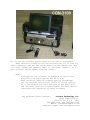
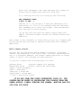
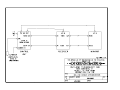
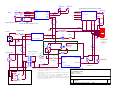
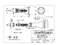
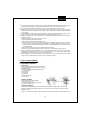
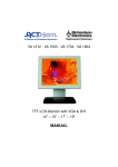
OUTLAND TECHNOLOGY INC. 38190 Commercial Court Slidell, Louisiana U.S.A. 70458 Ph.(985)847-1104, Fax 1106 Email: [email protected] Website: www.outlandtech.com LIMITED WARRANTY Outland has a strong commitment to high quality production. Each product has a twelve (12) month limited warranty against defects in workmanship or materials with the exception of those outlined in the limitations and exclusions. Outland will repair or replace at its discretion the defective components. Limitations and Exclusions • The limited warranty does not cover damage caused by improper use, poor maintenance or accidental damage of the product or its components. • The limited warranty does not cover items subject to wear including but not limited to view ports, o-rings, umbilical, unless found to be defective in workmanship and/or materials. • The limited warranty does not cover any modification made to these products without authorization from Outland Technology Inc. • The limited warranty does not cover lamps. • The limited warranty does not cover components damaged due to incorrect power connection per user’s manual. • The limited warranty does not cover items not actually built by Outland. Example (DVD recorder, Monitor etc.). That would be covered by the manufacturer's warranty. Advertising claims made by us represent our honest opinion of the qualities and features offered by the products described. We disclaim any warranties expressed or implied, including warranties of merchantability and fitness for a particular purpose, except as provided herein. In no event shall Outland Technology be liable for consequential damages of any kind. Shipping All returns for warranty service must be authorized by Outland. You must call or email Outland for a RMA#. The assigned RMA (Returned Materials Authorization) number which must be clearly indicated on each item returned for service. NOTE: To submit a product or its components for warranty a RMA form must be completed. Please complete as best and detailed as possible. For warranty shipping within the first 30 days, Outland will pay for ground shipment on domestic orders incoming and outgoing to a maximum of $75.00 each way. International shipments will be credited up to $75.00 US for incoming and outgoing freight charges to Outland Technology Inc. After 30 days the client is solely responsible for shipping to and from Outland Technology Inc. During the first 30 days of the warranty period, should faster delivery service be requested, a $75.00 US credit towards expedited freight for each applicable leg will be given. If you have any questions regarding the installation and operation of this equipment, or if more information is needed contact: OUTLAND TECHNOLOGY,INC., 38190 Commercial Ct.,Slidell, LOUISIANA USA 70458 (985)847-1104 FAX (985)847-1106 (Email) [email protected] (Website) http://www.outlandtech.com UWS-3110 OPERATING INSTRUCTIONS 1. To operate Camera System, all interconnections from the Control Unit, VCR & Monitor, should already be connected but in the event there is a problem drawing # 0010550 shows how those items connect. CAUTION: Insure voltage does not exceed 130 volts AC to the Console. Also power source must be properly grounded. 2. Plug Camera Umbilical into Camera and light (Be sure to use a good quality silicon grease for lubrication). Plug topside end of umbilical into Control Unit connector on front panel. 3. After verifying supply power is correct, insure camera, light, recorder and monitor switches are in off position. Plug into power source. 4. Turn Monitor, Recorder and Camera switches on. Within a few secs. a picture will appear. 5. Adjust Focus control to get a clear picture. (UWC-560 only) UWC-500 requires the Video Typewriter option. Hit the "Home" key to Zoom out and the "End" key to zoom in. Focus is automatic. To manually focus the UWC-500 hit the "+" key and then "Page up" and "Page down" to focus. To put back into automatic hit the "+" key. 6. Insure "Light Intensity" is at "Min" position. Turn light switch on. Turn control up to test light. Turn back to Min. and Turn switch off. CAUTION: " DO NOT OPERATE LAMP OUT OFF WATER FOR MORE THEN 5 SECONDS" . 7. The CON-3100 console has a LIM circuit (Line Insulation monitoring). The LIM circuit monitors the wires attached to the underwater light. If for some reason this line is exposed to sea water, such as a nick, cut or leakage, then the LIM circuit will energize a GFCI on the front panel. The indication of a leakage does not necessarily mean there is a safety problem but does mean there is a single fault that must be looked at when the cable and light are back on the surface. The light will not reset until the fault is repaired. If the GFCI resets on the surface it may be a cable problem. 8.) To Use the recorder please refer to the VCR or DVD manual: When initially turned on the DVD recorder may try to scan for cable channels. Just hit the return button on the Remote and this will stop. Change the channels until it goes pass channel 1 to L1 and a picture should appear from the camera. Note: Although the VCR recorder is Equipped to record and playback in multiple speeds the SP or 2 Hr. mode should be used for highest Quality recordings. The DVD recorder has several levels of record quality. XP is the highest but uses the most of the hard drive and DVD disk. Read the recorder manual for more details concerning the operation of these recorders. Any problems Please Contact: Outland Technology Inc. 38190 Commercial Ct. Slidell, La. U.S.A. 70458 (985)847-1104, Fax (985)847-1106 EMAIL: [email protected] Website: http://www.outlandtech.com TROUBLESHOOTING GUIDE ***************************************************************** SYMPTOM PROBABLE CAUSE REMEDY ***************************************************************** 1. Camera does Power cord not plugged in. Plug in. not come on. Fuse Blown Replace (In rear) GFI tripped Reset (In rear) Camera Umbilical not plugged in at Console or Camera. Connect. Camera switch not on. Turn on. Recorder not on or is in Play mode. Turn onPress stop. Recorder not in line mode. Push channel selector down until "L" shows on the display. Monitor not on. Turn on. Umbilical has a short or has broken wires. Check for continuity and/or shorts using Drawing # C-2301. Camera DC supply Bad. Check for 12-16 volts DC at camera umbilical connector between pins B & C. If no voltage check the GFI and the fuse at the rear of the console. ******************************************************************* 2. Light does Power cord not plugged in Plug in. not come on. Fuse blown. Replace.(In Rear) GFI tripped Reset (In Rear) Umbilical not plugged in at Console or Light. Connect. Bulb burned out. Replace using instructions (page 7). Umbilical has a short or has broken wires. Check for continuity and/ or shorts using Drawing # C-2301 ***************************************************************** CAUTION: CAMERA AND LITE SHOULD ONLY BE OPENED, BY QUALIFIED TECHNICIANS,IN A DRY ATMOSPHERE WITH PROPER TOOLS AND WORK AREA. ***************************************************************** CON-3100/VTW, Typing on screen, A. The Video typewriter powers up whenever the console is plugged in. The video always goes through the Video typewriter B. After powering on the system the screen should go to page zero "0". Anything in page zero will be displayed as well as time and date, if it were on the screen when it was powered off. C. Hit the “H” Key and the main menu will appear on the screen. D. Menu: (KEY)(FUNCTION) E EDIT PAGE 0 C CLEAR PAGE 0 T TIME OFF D DATE OFF S SET TIME R RESET SYSTEMS P SCALE (Ruler) X Cross Hair (Pointer) M Camera Mode I SET INTENSITY 1) E; Go to the Page you want to edit by touching the number key. Touch the letter “E”. This will bring you into the edit mode and you should see a Blinking cursor at the top left corner of the screen. Type in anywhere on the screen and when you finish hit the “ESC” key. The text will store in memory and the cursor will disappear. 2) C; Go to the page you want to clear and hit the letter C. The following will appear: ARE YOU SURE YOU WANT TO CLEAR PAGE 0 ? (Y/N) This will clear the page of all characters except the time and date. Select yes or no. 3) T; Hitting this key will turn the time either on or off. 4) D; Hitting this key will turn the date either on or off. 5) S; Hitting this key will allow you to set the time and date. The following will appear: ( 12,51,5,21,99) ENTER HR,MIN,MONTH,DAY,YEAR Input the time and date as shown with comas between each item followed by "ENTER". 6) R; Hitting this key will clear all pages. The following will appear: ARE YOU SURE YOU WANT TO CLEAR ALL MEMORY ? (Y/N) Select yes or no. The time and date will remain on screen. 7) P; Hitting this key will cause the Video Ruler to appear on the bottom of the screen. The Video typewriter time date features will continue to operate. The active keys to use this feature are: “O”, sets scale factor. 1=1, 2=2, 3=3, etc. for every tic mark. Minus for tic marks to the left and + for each tic mark to the right. The digital display below and to the left of the scale is where on the Ruler the cursor marker is in relation to the center of the scale. “Left Arrow” Key moves the cursor to the left on the ruler. “Right Arrow” Key moves the cursor to the right on the ruler. The digital display moves up and down as these arrow keys are used. “Home” Key moves the ruler tic marks wider. “End” Key moves the ruler tic marks closer. “Page Down” moves the center (offset) of the ruler Left. “Page Up” moves the center (offset) of the ruler Right. To use this feature set the scale factor for the required measurement. Move the center (offset) of the ruler to the center of the item to be measured. A reference must be used to accurately measure with the Video Ruler. If Laser dots are use then scale the ruler to those dots. Once the ruler is scaled using the “end” and “Home” Keys, use the arrow key to show the measurement. 8) X; Hit this key and a Crosshair will appear on Screen. Use the cursor keys to move the crosshair (Video Pointer) around the screen. In this mode the Scale will disappear. The time and date will remain on Screen and all page functions will work also. 9) I; Hitting this key will bring up the following: SET INTENSITY LEVEL 0 MIN, 15 MAX > Default is 3. If you enter 0 then the characters will turn black. If 14 or 15 are entered then the character will probably be a little too bright. Play around with this and set for best display. 10) M; Hit this key and the camera control menu will appear. See Multi Camera control for details about this function. Note: When in the Crosshair or Scale mode you can go to Camera mode by hitting any key not used to operate those functions. Example: Space Bar. Multi Camera control, Hit the “M” key and select which camera to control. If several cameras are connected to the serial data line each camera must be set to a different address. The single camera operation is always camera 0 "zero". Call Outland for more details. To control a camera the following keys are used: Up/Down Arrow Controls camera tilt up/down Left/Right Arrow Control camera Pan left/right “Home” = Zoom Telephoto “End” = Zoom Wide “Page up” = Focus Far “Page down” = Focus Near “+” key = Auto-Focus on/off IF AT ANY TIME THE VIDEO TYPEWRITER LOCKS UP, THE SYSTEM CAN BE RESET BY UNPLUGGING THE CONSOLE FROM THE POWER SOURCE. SIMPLY TURNING THE CAMERA, MONITOR AND VCR OFF WILL NOT WORK. J6 A UDIO OUT J7 A UDIO OUT 0010460 MODEL 510 0 V IDEO OVERL AY OPTION J5 1 2 3 MIC IN T2 4 5 J4 0010225 MIC MIC OFF GND L OUT GND L IN GND 4(GND) BLK V ID OUT J8 IBM KEY BOARD 2(DA TA ) Y ELL 8 9 V IN GND V IDEO OUT 1(CLK) PUR 6 7 V ID IN 5(PWR) RED A UDIO MIXER 2A 3A G SB FUSE F1 1 2 A C PLUG L 2 1 Meanw e ll RS- 35-15 +V L N GND -V 4 Red wir e 5 Black w ire C 2a S3 220 V A C 2 2b 1a 1b 1 110 V AC 11 White w ire 9 R3 10k 2W 1 1.5A SB 110V 3AG S1 1 2 LINE BLK LOA D BLK LINE WHT LOA D WHT 3 LP1 LA MP NEON GFI Pow er R1 10k 2W 10 White w ire GFI, Cooper 1. ADJU ST 15 VPS FO R 14.5 VOLTS. 2. ADJU ST R2 SO THA T GFI JUST TR IPS WHEN 1.4K IS APPL IED TO PIN G OF J3. 3. DELE TE S3 AND AD D DOTTED LINE WIRES ON T1 FOR 110 VAC ONLY O PTION. 4. FOR 110/220 OPTI ON J2 = DUAL IEC FEMALE RE CPTACLES. FOR 110 ONLY J2 = 1 10 VAC DUPLEX RECPTACLE. 5. FOR VIDEO OVERLA Y OPTION ADD MODEL 5100 VI DEO OVERLAY AS SHO WN AND DELET E DOTTED LINE WIRES BETWEE N VIDEO OUT JACK J8 AND PIN A OF J3. 1 NOTES: Black w ire 4 7 F2 CAMERA CABLE 2 6 11 8 3 2 5 TRIAD N PS230-760 12 2 T1 1K ISO PV T422 OPTO FET 2 1 LED C1 + H Signal A 41-17 5-230 R5 1 220uF 16V R2 10K D1 4 Black w ire A C RECPTA CLE J2 A B C D E F G H 2 MS-3102 A-18-08S 15V PS 1 White w ire J3 S2 CA MERA POWER 3 J1 N 12 COMM+ 1 13 COMM- 600:600 OHM TELE XFORMER ( TY -145P) V+ V- A UDIO LINE IN ISOL ATED T2 V A RIA C 17 1 OUTLA ND TECHNOLOGY INC. 38190 COMMERCIA L COURT SLIDELL, LA . 70 458 (98 5)847- 1104, FA X 11 06 Title CU-3100 POWER SUPPLY Size A Document Number 0204098 Date: We dnesday, November 01, 2 006 Rev C Sheet 1 of 1 OUTLAND TECHNOLOGY INC. UWL-200 UNDERWATER LIGHT Operating and Maintenance Procedures Reference: DRAWING 0010499 Installation and Operation: (CAUTION: WHEN OPERATING THIS LIGHT, WITH 115 VAC, A ISOLATION TRANSFORMER OR GROUND FAULT INTERRUPTER IS REQUIRED). A. The UWL-200, can be mounted to your Camera, ROV, Helmet or Hand bracket by using DH-50 OR HM-300 helmet bracket. B. With Power Off, lubricate the light mating connector with a light coating of silicon lubricant. slide the locking sleeve of the mating connector back. Align the raised dot on the connector with the large connector pin on the light connector and plug in. Securely tighten the locking sleeve. C. Do not Operate the Light in air for more then 5-10 seconds. Bulb Replacement Procedure: A. Prepare a clean dry area for disassembly and assembly. B. Make certain power to the light has been turned off. C. Unscrew the locking sleeve and remove the mating connector from the light. Securely grasp the mating connector as close to the light as you can and unplug from the light by holding onto the light as you pull. D. Remove the connector from the light by unscrewing it from the base. Use a crescent wrench or channel locks (on the flats of the connector), being careful not to damage the sealing surfaces of the connector. E. Remove the bulb by grasping it near the base and unscrewing it. F. Clean and inspect the connector "O"-Ring. Replace the "O"-Ring if it appears damaged in any way. G. Put a light coat of silicon on the "O"-Ring, and the sealing surfaces which contact the "O"-Ring and place it back on the connector. H. Unwrap the replacement bulb being extremely careful not to touch the quartz envelope. If it is accidentally touched, clean the bulb thoroughly using alcohol and a soft tissue before installing. I. Screw-in the new bulb and replace the connector. Tighten snug. CAUTION: DO NOT OVER-TIGHTEN. Port Replacement Procedure: Unplug the light from the cable. Remove the "C" clip. Remove old port and "O" Ring. Clean and check "O" ring surfaces. Lubricate new "O" ring with Silicon Grease and install in Groove. Clean the port and install. E. Install the "C" clip and press down firmly to cause the "C" clip To snap into the groove. Make sure it is completely seated and the "O" ring is firmly sealed to the port. A. B. C. D. VT-288V 12" LCD MONITOR ENGLISH Federal Communications Commission (FCC) Statement This Equipment has been tested and found to comply with the limits for a class B digital device, pursuant to Part 15 of the FCC rules. These limits are designed to provide reasonable protection against harmful interference in a residential installation. This equipment generates, uses and can radiate radio frequency energy and, if not installed and used in accordance with the instructions, may cause harmful interference to radio communications. However, there is no guarantee that interference will not occur in a particular installation. If this equipment does cause harmful interference to radio or television reception, which can be determined by turning the equipment off and on, the user is encouraged to try to correct the interference by one or more of the following measures: - Reorient or relocate the receiving antenna. - Increase the separation between the equipment and receiver. - Connect the equipment into an outlet on a circuit different from that to which the receiver is connected. - Consult the dealer or an experienced radio/TV technician for help. Warning: A shielded-type power cord is required in order meet FCC emission limits and also to prevent interference to the nearby radio and television reception. It is essential that only the supplied power cord be used. Use only shielded cables to connect I/O devices to this equipment. You are cautioned that changes or modifications not expressly approved by the party responsible for compliance could void your authority to operate the equipment. IMPORTANT SAFEGUARDS Warning: 1. Read all of these instructions. 2. Save these instructions for later use. 3. Unplug this monitor from the wall outlet before cleaning. Do not use liquid cleaners or aerosol cleaners. Use a damp cloth for cleaning. 4. Do not use attachments not recommended by the monitor manufacturer as they may cause hazards. 5. Do not use this monitor near water. For example near a bathtub, washbowl, kitchen sink, or laundry tub, in a wet basement, or near a swimming pool, etc.. 6. Do not place this monitor on an unstable cart, stand, or table. The monitor may fall, causing serious injury to a child or adult, and serious damage to the appliance. Use only with a cart or stand recommended by the manufacturer or sold with monitor. Wall or shelf mounting should follow the manufacturer's instructions, and should use a mounting kit approved by the manufacturer. 7. Slots and openings in the cabinet and the back or bottom are provided for ventilation, and to insure reliable operation of the television receiver and to protect it from overheating, these openings must not be blocked or covered. The openings should never be blocked by placing the monitor on a bed, sofa, rug, or other similar surface. This monitor should never be placed near or over a radiator or heat register. This monitor should not be placed in built-in installation such as a bookcase unless proper ventilation is provided. 8. This monitor should be operated only from the type of power source indicated on the marking label. If you are not sure of the type of power supplied in your home, consult your monitor dealer or local power company 9. This monitor is equipped with a three-wire grounding type plug, a plug having a third (grounding) pin. This plug will only fit into a grounding-type power outlet. This is a safety feature. If you are unable to insert the plug into the outlet, contact your electrician to replace your obsolete outlet. Do not defeat the safety purpose of the grounding- type plug. 10. Do not allow anything to rest on the power cord. Do not locate this monitor where the cord will be abused by persons working on it. 11. Follow all warnings and instructions marked on the monitor. 1 ENGLISH 12. For added protection for this monitor, when it is left unattended and unused for long periods of time, unplug it from the wall outlet. This will prevent damage to the monitor due to power-line surges. 13. Do not overload wall outlets and extension cords as this can result into fire or electric shock. 14. Never push objects of any kind into this monitor through cabinet slots as they may touch dangerous voltage points or short out parts that could result in a fire or electric shock. Never spill liquid of any kind on the monitor. 15. Do not attempt to service this monitor yourself since opening or removing covers may expose you to dangerous voltage or other hazards. Refer all servicing to qualified service personnel. 16. Unplug this monitor from the wall outlet and refer servicing to qualified service personnel under the following conditions: a. When the power cord or plug is damaged or frayed. b. If liquid has been spilled into the monitor. c. If the monitor has been exposed to rain or water. d. If the monitor does not operate normally by following the operating instructions. Adjust only those controls that are covered by the operating instructions as improper adjustment of other controls may result in damage and will often require extensive work by a qualified technician to restore the monitor to normal operation. e. If the monitor has been dropped or the cabinet has been damaged. f. When the monitor exhibits a distinct change in performance- this indicated a need for service. 17. When replacement parts are required, be sure the service technician has used replacement parts specified by the manufacturer that has the same characteristics as the original parts. Unauthorized substitutions may result in fire, electric shock, or other hazards. 18. Upon completion of any service or repairs to this monitor, ask the service technician to perform routine safety checks to determine that the monitor is in safe operating condition. 12’’TFT COLOR MONITOR 1. Installing the Monitor Unpacking Open the shipping cartons and check the contents. If any items are missing or damaged, contact your dealer immediately. The package should include the following items: ․TFT color monitor ․User's guide ․Power cord ․Signal cable ․DC power adapter ․Audio cable Installing the Base Follow these steps to install the base: 1. Turn the monitor down. 2. Assembly the base to the arm with screw. 3. Tie the screw with a coin. Installing the Monitor This monitor is equipped with an auto sensing DC power adapter for voltage ranges 100-240VAC, 60/50Hz. Confirm the line voltage designation on the rear panel of the monitor. Follow these steps to install the monitor: 1. Before you connect the cables, made sure that the monitor and the system unit power switches are 2 ENGLISH off. 2. Plug one end of the 15pin-signal cable to the monitor and the other end to the video signal connector at the rear of the system. Tighten the two screws on the cable connector. 3. Connect the DC power cord to the DC jack. 4. Connect the power cable. 2. Control Functions The monitor digital control functions are located on the front panel. They are shown in the figure below and described in the following paragraphs. 1.Power Switch with Indicator LED 2.Function Keys 3. Function Select With the △ and ▽ knobs, you can adjust the speakers volume. Press the MENU/SELECT knob to show the OSD menu. Than use the △ and ▽ knobs to select a function. Press the AUTO/EXIT knob to close the OSD menu. You can hold the AUTO/EXIT knob for more than 3 second to adjust the image quality automatically. The OSD menu will close automatically after 3-10 seconds without operation and saves any changes you have made. 4. Function Adjustment 1.Signal Select VGA DVI Exit - Select the image signal coming from the VGA cable. - Select the image signal coming from the DVI cable.(option) - Close the Signal Select OSD menu. 2.Video Brightness Contrast Black Level Exit - Adjust the luminance level in the image. - Adjust the difference in luminance between light and dark areas of the image. - Adjust the black Level in the image. - Close the Video OSD menu. 3.Audio Volume - Adjust the volume of speakers. Exit - Exit the Audio OSD menu. 4.Color Color Temperature User - Adjust the R.G.B. gain level. 6500K - Select color temperature to 6500°K. 9300K - Select color temperature to 9300°K. Exit - Close the Color Temperature OSD menu. Flesh Tone - Adjust the flesh tone of the image. Hue - Adjust the shade of the image color. Saturation - Adjust the saturation of the image color. 3 ENGLISH Exit - Close the Color OSD menu. 5.Image Auto Tune H. Width H. Phase H. Position V. Position Exit 6.Language - Adjust geometry of the image automatically. - Adjust the horizontal sync size of signal. - Adjust the horizontal sync phase of signal. - Adjust the horizontal position of the image. - Adjust the vertical position of the image. - Close the Image OSD menu. - Sets the language of the OSD windows. 7.Tools OSD Control Recall Sharpness Exit 8.Exit OSD Timer - Setting the OSD menu display time. OSD H. Position- Adjust the horizontal position of the OSD menu. OSD V. Position- Adjust the vertical position of the OSD menu. Exit - Close the OSD Control OSD menu. - Recall the factory default setting. - Adjust the picture display more clear. - Close the Tools OSD menu. - Close the OSD menu. 5. Micro-controller Features The micro-controller automatically detects the video board installed in your system. When you turn on the monitor, the micro-controller first checks the display mode memory stored in the user setting area of the video board, and then the factory presetting area. It then adjusts to the proper display mode. 6. Display Modes Memory The micro-controller has the memory capacity to store different display modes, including timing formats and display-settings. Factory Presetting Area There are some preferred display modes preset in the micro-controller. These display modes are preset at the factory and include the most popular display modes currently available. The micro-controller searches for a proper display mode in this area if it fails to find a proper display mode in the user setting area. MODE 1. 2. 3. 4. 5. 6. VGA VGA VGA VESA/75 VESA/60 VESA/75 Resolution (Dots*lines) 640×350 720×400 640×480 640×480 800×600 800×600 Horizontal Freq.(KHz) 31.5 31.5 31.5 37.5 37.9 46.9 4 Vertical Freq.(Hz) 70 70 60 75 60 75 Remark Non-interlaced Non-interlaced Non-interlaced Non-interlaced Non-interlaced Non-interlaced ENGLISH 7. Signal Connector Pin-outs To connect VGA, 8514A or IBM-compatible graphics adapters, use a 15 pin mini D-type male connector. 15-pin Mini D-type Male Connector Pin Assignment 1 Red Video 2 Green Video 3 Blue Video 4 Ground 5 No Connection 6 7 8 9 10 Red Ground Green Ground Blue Ground No Connection Sync Ground 11 12 13 14 15 Ground Serial Data/I/O H. Sync V. Sync Serial Clock Input 8. Power Saving Feature When the power saving active them the power indicator LED will be from Green Light to Amber, And power saving feature complies with these VESA power saving modes: Power Consumption Normal On On Green <30W Stand-by Off On Amber < 3W Suspend On Off Amber < 3W Off Off Off Amber < 3W The monitor uses the H. Sync and V. Sync signals to determine the operation mode to enter. The monitor power-saving feature automatically turns off H. Sync and V. Sync if there is no input from the system for a certain period of time. To use this feature, you need a green PC that is compliant with the VESA power saving feature or a software utility to detect system input such as keyboard or mouse. Mode H. Sync. V. Sync. LED Time Settings Time settings are adjusted from the system unit by software. To fulfill the requirements in the NUTEK specification 803299/94 the total time from indicated inactivity to Power Saving position A2 (VESA OFF) must not be set more than 70 minutes. We recommend you switch off the monitor when you do not intend to use it for awhile. 5 ENGLISH 9. Specifications Model LCD Panel Size: Pixel Pitch: Brightness: Contrast Ratio: Response Time: Maximum viewable size Video Input Display area Power supply (Universal) Input voltage: Consumption External controls Horizontal frequency Vertical frequency Dimensions(with carton) Max. Resolution Power Saving Plug & Play Weight 288 12” 0.3075mm 400cd/㎡ 500:1 35ms(typ.) 12 inch(30.5cm) Analog:15-pin, D-sub connector Digital:DVI connector(option) 246mmx184mm 12V DC/2.5A 30watts maximum Power-switch,VGA,DVI(option),Brightness,Contrast, Black level,Volume,Color tempeture(User,6500°K, 9300°K),Flech tone,Hue,Saturation,H-width,H-phase, H-position,V-position,OSD control,Recall,Sharpness,Exit 30-47KHz 50-75Hz 365mm×195mm×340mm (W×D×H) 800×600 (Non-Interlaced) With EPA standard DDC 1/2B N.W.:2.4Kgs G.W.:3.0Kgs Ambient temperature Operation: Non-operating Humidity Operating: Storage: *Specifications are subject to change without notice. 6 5°C – 35°C -20°C – 60°C 20%-80% 10%-90%