1
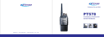
PT568
FM HANDHELD TRANSCEIVER
INSTRUCTION MANUAL
NOTE:
NOTE:
INSTRUCTION MANUAL
PT568
FM HANDHELD TRANSCEIVER
We are very grateful for your purchasing
brand two-way radios
produced by Kirisun Electronics (Shenzhen) Co., Ltd.
We believe
two-way radio, which always incorporates the latest
technology, can bring great convenience to your life and work;
We also believe that the quality and function of
meet your demands for reliable communication.
402-E1300A-RD7A
23
two-way radio can
Notice to the User:
* Government laws prohibit radio communication
without permission in areas dominated by the government.
* Illegal operation is subject to punishment by fine
and/or imprisonment.
* Refer service to the well-trained professional technicians only.
Safety
It is important that user is aware of and understands
hazards common to the operation of any radios.
Warning!
Turn off your radio before entering any area with a potentially explosive atmosphere (where the air contains
gas, dust and smog, etc.), such as while taking on fuel,
or while parking at a gasoline service station.
Precautions in Use
Please comply with the following attentions to avoid
fire, bodily injury and damage to the radio.
* The radio is recommended to transmit for 1 minute
and receive for 4 minutes. Long time transmitting or continuous working in high power mode will make the rear
side of the radio generate heat.
* Please do not disassemble or assemble the radio under any circumstances.
* Please do not expose the radio to direct sunlight for a
long time; do not place the radio near any heating devices, either.
* Please do not put the radio in extremely dusty, moist or
dabbling places; do not place it on any unstable surface,
either.
* If the radio emits smoke or strange odors, turn it off and
remove the battery from the radio and contact your local
authorized Kirisun dealer without delay.
Contents
1. Open Package Inspection........................1
Firstly, please take the radio out of the pac-
2. Preparation.............................................2
kage box carefully. We recommend checking
2.1 Charge the battery................................3
the supplied accessories in the following table
2.2 Install/Remove the battery.....................4
2.3 Install the antenna................................5
2.4 Install external speaker/MIC.................6
2.5 Install the belt clip..................................7
2. Preparation
2.1 Charge the battery
Insert the cable plug of
Antenna
Power
Adapter
before disposing the packing material. If any
the adapter into the jack at
the back of the charger.
Then insert the adapter into an
article is found lost or damaged, please contact
applicable AC power output socket. The three LEDs
the distributor without delay.
will flash for about one second, and then the green LED
will be constantly on when the charger is normal.
Quantity
3. Radio Overview........................................8
Accessories
4. Basic Operation.......................................9
Antenna
1
5. Functions of Programmable Buttons.......10
Battery
1
turn off the radio before
Belt Clip
1
inserting it into the charger.
Rapid Charger
1
Power Adapter
1
Hand Strap
1
Instruction Manual
1
6. Auxiliary Functions.................................11
7. Wired Clone Mode................................. 12
8. Troubleshooting Guide...........................13
9. Major Specifications...............................14
10. FCC Notice.........................................15
1
1. Open Package Inspection
Battery
Rapid
Charger
Insert the battery to be charged or the radio into the
charger. Do remember to
Make sure that the battery
and the charger terminal
are fully and reliably
Belt Clip
Hand Strap
connected with each other.
When the red LED is on, the charging starts.
2
* Both KB-56A lithium polymer battery and KB-56B
* KB-56A/KB-56B battery is provided with an internal
Press the lower end
lithium polymer battery of the company are applicable
protective circuit. When the battery power is too low,
of the battery down until
to this radio.
the battery will cut the power supply automatically. If
the latch of the radio com-
* Charge the battery for several times for the first ch-
it is charged on the charger now, the red LED will not
pletely bounces out, and the
arging after purchase or after the radio is laid aside for
be on immediately. After about 1 to 5 minutes, the
battery is locked.
In doing so, the battery can reach its best performance.
a long time (longer than 2 months), so that the battery
charging indicator will turn normal.
Then you can remove the adapter from the AC power
can reach its normal battery capacity. Meanwhile, pl-
2.2 Install/Remove the battery
output socket.
ease make sure to charge the battery at least once
After about five hours of charging, the red LED will
be out, and the green LED will be on, which indicates
that the battery is fully charged.
Keep the battery in the charger under green LED
on status for 1 to 2 hours, and then remove the battery.
If the yellow LED flashes, it indicates that the ch-
every three months.
arging temperature or the circuit is abnormal, and the
* It is better not to recharge the battery if the battery is
charger is in the protected status, in which you should
fully charged or the radio is not in its low battery alarm
not charge the battery compulsorily.
status; otherwise, the battery's service life and perf-
Please remove the battery and cut the power of the
Align the two protrusions at the upper end of the
battery to the slots at the upper end of the shell of the
To remove the battery, please push the latch at the
lower end of the radio forward, the lower part of the
battery will bounce up automatically. Then, loose the
belt clip slightly and remove the battery.
radio and insert them.
ormance may be influenced. After the battery charging
charger.
is finished, please remove it from the charger.
Note:
* When the radio enters the low battery alarm status,
* The radio battery has not been charged in the fac-
please recharge the battery before reusing it. Do not
tory; please charge the battery before using the radio
turn on the radio compulsorily; otherwise, the service
for the first time.
life and performance of the battery may be influenced.
3
Install the battery:
Remove the battery:
4
Note:
Please avoid short circuit of the battery terminals and
2.4 Install external speaker/MIC
Open the cover of the jack
do not throw the battery into fire.
for external speaker or microp-
Do not tear down the shell of the battery by yourself.
hone, and then insert the plug
until you hear a click to turn on the radio, and counter-
⑦
clockwise until you hear a click to turn it off.
①
rophone into the jack on the radio.
If the radio is on, turn the Power/Volume control knob
clockwise or counterclockwise to adjust the volume.
of the external speaker or mic-
2.3 Install the antenna
Rotate the Power/Volume control knob clockwise
3. Radio Overview
④
⑧
⑤
⑥
Hold the base of the antenna and turn the antenna
4. PTT (Push-to-talk) button
Press and hold the PTT button and talk to the microphone, your voice can be sent to the recipient. Rele-
clockwise into the connector on the top of the radio
ase the PTT button to listen.
until the antenna is fastened.
5. Side button 1 (programmable button)
2.5 Install the belt clip
6. Side button 2 (programmable button)
Align the two holes on the upper
part of the belt clip to the screw holes
at the back shell of the radio, and
then fix the belt clip to the radio with
two 2.5×8.0 screws.
Loose the fixing screws to remove
the belt clip.
1. LED indicator
Solid red — The radio is transmitting.
7. Top button (programmable button)
Note: Only top button can be set as Emergency
Solid green — The radio is receiving.
Alarm button.
Blinking red — The radio is in low battery.
8. Speaker/MIC jack
2. Channel selector knob
Rotate the knob to select channels 1-16.
External speaker and microphone can be connected
to the radio through this jack.
3. Power/Volume control knob
5
6
4. Basic Operation
③ Selecting a channel
⑤ Receiving
① Powering up the radio
Rotate the channel
Release the button, the radio will return to the recei-
Description
of voice announcement, meanw-
Rotate the Power/Volume
selector knob to select the
ving status. The dealer may have programmed
hile, the current channel number
control knob clockwise to
required channel. When
CTCSS/DCS signaling in your radio. On the channels
can be heard.
turn on the radio. If the
correct signals are rec-
with CTCSS/DCS signaling programmed, you can only
dealer has set the alert tone,
eived, you can hear
hear calls from other radio with the same CTCSS/DCS.
a sound of “Bee” will be heard.
sounds from the speaker.
NO. Function
2
Talkaround
karound” button is pressed, the
transmitting frequency will be the
5. Functions of Programmable
same with the receiving freque-
② Adjusting the volume
ncy if the radio transmits again.
Press the preprogrammed “Squelch Off” button to
④ Transmitting
Buttons
hear background noise. Then rotate the Power/Vol-
Press and hold the PTT button
The dealer can assign one of the following
ume control knob to adjust the volume.
and speak to the microphone
auxiliary functions to the top button, side button
in normal voice to send a call.
1 or side button 2.
Please keep the microphone
NO. Function
5 to 10 cm from your mouth.
7
When the preprogrammed “Tal-
3
Description
No function is assigned.
Lone
Press the preprogrammed “Lone
Worker
Worker” button to enable/disable
the lone worker function.
4
Emergency
Press the preprogrammed “Eme-
Alarm
rgency Alarm” button to make al-
0
None
1
Voice Anno- Press the preprogrammed “Voice
of the programming software or
uncement
Announcement Selection” button
send your ID or background sound
Selection
to switch the language and mode
to your partner or the system.
arm tone according to the setting
8
Description
NO. Function
Emergency Alarm Press the preprogrammed “Emergency Alarm Off” button to quit the Emergency Alarm
5
Off
Mode.
6
Scan
Press the preprogrammed “Scan” button to enable/disable the system scan function.
7
Nuisance Delete
If the scan function of the radio is enabled, and the radio stays at the noise channel,
(temporary)
press the preprogrammed “Nuisance Delete” button to delete the noise channel temporarily.
8
High/Low
Power Switch
9
10
Press the preprogrammed “High/Low Power Switch” button to switch between high and
low transmitting power of the radio.
Momentary
Press and hold the preprogrammed “Momentary Monitor” button to disable CTCSS, DCS
Monitor
signaling, and release the button to resume normal operation.
Monitor
Press the preprogrammed “Monitor” button to disable CTCSS, DCS signaling, and you can
receive signals that cannot be heard under normal operation. Press it again to resume
normal operation.
11
12
9
6.1 Time-Out Timer (TOT)
1) TOT Function
a) TOT timer is provided to prevent the user from
talking too long and occupying the channel for a long
time, and to avoid too long continuous transmission
of the radio.
b) Set the time limit for continuous transmission
of the radio. When the transmission time exceeds the
preset time limit, the radio will make alarm and stop
3) TOT Pre-alert
a) The radio will alarm in advance before the transmission is stopped by the timer.
b) After the pre-alert tone, if the transmission time
exceeds the preset time limit, the timer will act.
4) TOT Reset Time
a) The time period from the releasing of the PTT button
to the reset of the timer.
b) If the release time of the PTT button is shorter than
the TOT reset time, the timer will continue to countdown.
transmission.
2) TOT Rekey Time
a) Set the time period in which the radio is prohib-
Momentary
Press and hold the preprogrammed “Momentary Squelch Off” button to open squelch;
Squelch Off
release it to resume normal operation.
ited to transmit after the transmission time exceeds
Squelch Off
Press the preprogrammed “Squelch Off” button to open squelch. Press it again to resume
the preset time limit.
operation.
13
6. Auxiliary function
6.2 Battery Saving
The dealer can set the power saving mode of the
battery.
If this function is enabled, and the radio receives no
b) During the period in which the radio is prohibited
signal or no operation has been performed for ten se-
Lone Worker
If Lone Worker function is enabled, press the preprogrammed “Lone Worker Reset”
to transmit, if the PTT button is pressed, an alert tone
conds, the radio will enter Battery Saving Mode. If the
Reset
button to reset the lone worker timer, and the timer starts again.
will be sounded, and the transmission is prohibited.
radio receives signals or the user operates the radio,
10
the radio will automatically exit the Battery Saving
Mode.
There are four modes of battery saving: 1:1, 1:2,
If change the channel by channel selector knob,
* If the decoding requirement is strict and it requires
the radio will announce the number of the selected
long decoding time, please set the battery saving mode
channel after the selection is finished.
as “Off” or “1:1”.
1:4 and Off.
Battery saving function can reduce power consumption of the battery.
6.7.1 Enable/Disable the scan function
a) Press the preprogrammed “Scan” button to enter
the scan mode. During the scan process, the radio will
scan channels in the scan list until signals are found.
6.5 CTCSS/DCS
6.6 Talkaround
Then the radio will stay at the channel with signals until
The dealer may have programmed CTCSS or DCS
In the communication network, you can expand
the signals disappear. If the time delay between signal
signals on channels of the radio. Through this, other
communication range through a repeater. If the radio
disappearance and scan resumption is set, the radio
irrelevant calls using the same channel can be ignored.
is out of the communication range, you can connect with
will stay at the current channel even if it receives signals
If the battery voltage is too low, the indicator will
If a channel has set CTCSS or DCS signals, the radio
other radios through “Talkaround” mode.
during the time delay.
flash. During the transmission process, if the battery
will open squelch only when receiving correct CTCSS
Press the preprogrammed “Talkaround” button to
reaches the preset low limit, the red indicator will flash.
or DCS signals. Similarly, only radios with the CTCSS/
switch between “Talkaround” mode and “Repeater”
If the battery is extremely low, the radio is not capable
DCS signals conforming to that of your radio can rec-
mode.
of transmitting signals.
eive your signal.
6.3 Low Battery Alarm
Note:
6.4 Voice Announcement
* It seems that once you use CTCSS/DCS, you can
6.7 Scan
In order to receive signals from many different
channels, the radio can be programmed to scan these
dealer. There are two languages available: Chinese
set the same CTCSS/DCS signals with your radio, they
channels.
and English.
can still hear your calling.
11
You can select one channel in the scan list as the
priority channel, which has the highest priority during
the scan. The radio will scan a non-priority channel first,
have your own channel. However, if other radios have
This function can be enabled or disabled by the
b) Priority Scan:
then the priority channel, and then the next non-priority
channel, and then the priority channel again, and the
scan goes on like this. If the priority channel and the look
back time are set for the current scan list, when the radio
is receiving signals on a non-priority channel, and the
12
scanning is paused, the radio will check the priority
transmit on the priority channel.
channel at the preset intervals. If there are signals in
Last Rx channel: The radio will transmit on the last Rx
the priority channel, it will stay at the priority channel;
channel of the scan list.
rogrammed “Lone Worker” button to enter Lone Worker
the preset alarm tone or send the background sound
if there is no signal, it will return to the original channel.
Last Tx channel + Current channel: If the scan is
Mode. Then the lone worker timer is started. If the pr-
to your partner or the system.
c) The revert channel (Tx channel) during the scan
paused, the radio will transmit on the current commu-
eset lone worker time expires, the radio will make ale-
In the Emergency Alarm Mode, press the prepr-
can be designated by the dealer. There are following
nication channel. Otherwise, the radio will transmit on
rt tone. If the preset remind time expires, the radio will
ogrammed “Emergency Alarm Off” button to quit the
options available:
the last Tx channel of the scan list.
enter Emergency Mode and give out emergency alarm.
Emergency Alarm Mode, disable or stop sending the
In the Lone Worker Mode, press the preprogrammed
alarm tone, and the radio will resume normal operation.
Scan start channel: The radio will transmit signals
on the channel for which the scan list applies.
6.7.2 Nuisance delete
Scan start channel + Current channel: If the scan
If a channel continually generates unwanted noise
is paused, the radio will transmit on the current co-
or interference, the preprogrammed “Nuisance Delete”
mmunication channel. Otherwise, it will transmit on
button can be pressed to remove the channel from the
the channel for which the scan list applies.
current scan list temporarily.
Priority channel: The radio will transmit on the pre-
Note:
set priority channel.
* The priority channel and the last channel in the scan
Priority channel + Current channel: If the scan is
list cannot be deleted.
paused, the radio will transmit signals on the current
* Quit the scan mode and enter it again, the deleted
communication channel. Otherwise, the radio will
channel will be added to the scan list again.
13
6.8 Lone Worker
If lone worker function is enabled, press the prep-
debounce time of the emergency alarm switch) to enter
the Emergency Alarm Mode. You can choose to make
“Lone Worker” button again to quit Lone Worker Mode.
In the Lone Worker Mode, press the preprogram-
7. Wired Clone Mode
med “Lone Worker Reset” button (if a button is desig-
If the wired clone function is enabled, the radio will
nated as the lone worker timer reset button) or any
not quit automatically after entering the Wired Clone
button (if any button is designated as the lone worker
Mode. To return to normal user mode, the user needs
timer reset button) to restart the lone worker timer.
to restart the radio.
The operating steps go as follows:
6.9 Emergency Alarm
Press the preprogrammed “Emergency Alarm”
button (the pressing time should be longer than the
1. Press and hold side button 2 while turning on the
radio to enter Clone Mode. If the wired clone function
is disabled, the radio will enter User Mode.
14
2. Connect the slave radio with the master radio by
No. Problem
a clone cable. Then turn on the slave radio.
Causes and Solutions
Please reinstall the battery.
3. Press side button 1 of the master radio, the cloning
B. The protective tube of the power
3
No. Problem
Causes and Solutions
please change it.
No. Problem
Causes and Solutions
D. The mixer tube is broken, please
No talkback A. The frequencies of the two radios
change it.
supply is burnt out. Please change it.
are not the same. Please select a
E. The FM processing IC is broken,
C. The power switch is in failure.
channel which has the same freq-
please change it.
Please change it.
uency with that of the other radio.
LED of the master radio will be off, and the slave radio
D. The battery is out of power, please
B. The CTCSS/DCS signals of the
5 The red LED A. The power module is broken, so
(Tx) lights there is no power output. Please
will restart automatically.
recharge it or change it.
two radios are not the same. Please
E. The CPU is broken, please cha-
reset it.
nge it.
C. The radio is out of effective co-
starts. During the data transmission process, the
master radio will light up red, and the slave radio will
light up green. When the cloning is finished, the red
4. You can continue to clone data according to step 3.
Note: The wired clone function can be enabled or
disabled by the PC programming software. Once the
wired clone function is disabled, the radio cannot enter
8. Troubleshooting Guide
Causes and Solutions
1 Power on failure A. The battery and the radio
are not reliably connected.
15
Phase lock A. The channel frequency setting is
loop unloc- out of range, please reset the chaked (Beep- nnel data.
Wired Clone Mode.
No. Problem
2
mmunication range.
ing)
4
No Rx
A. The antenna is in poor contact.
signals
Please fasten the antenna head.
B. The crystal oscillator of phase
B. The HF amplifying tube is broken,
lock loop is broken, please change it.
please change it.
C. The oscillating tube is broken,
C. The squelch level is so high that
please change it.
the squelch cannot be opened.
D. The phase lock loop IC is broken,
Please reset the squelch level.
up, but no
change it.
sound is
B. The microphone is broken, please
heard
change it.
6 The green
A. The speaker is broken, please
LED (Rx)
change it.
lights up,
B. the audio amplifier is broken,
but no sound please change it.
is heard.
16
9. Major Specifications
General Specification
Frequency
electromagnetic energy is within the
136-174MHz, VHF
FCC allowable limits for occupational
400-450MHz, UHF
man Exposure to Radio Frequency Electromagnetic
use, always adhere to the following
420-470MHz. UHF
Fields.
Channel spacing
25kHz(wideband)/
12.5kHz(narrowband)
111mm×52.5mm×33.5mm
249g(including battery
and antenna)
Operating temperature -25℃ ~+55℃
Receiving sensitivity
≤0.28μV
Frequency stability
2.5ppm
Tx power
4W (UHF), 5W(VHF)
Max. frequency
±2.5KHz(narrowband)/
deviation
±5KHz(wideband)
Max. audio power
Power supply
17
To ensure that your expose to RF
Evaluating Compliance with FCC Guidelines for Hu-
Pt568
16
Weight
ation of such levels for exposure to humans:
FCC OET Bulletin 65 Edition 97-01 Supplement C,
Channel number
Dimension(L×W×H)
10. FCC Notice
≥1000mW
DC7.4V
Your KIRISUN radio generates RF electromagn-
American National Standards Institute (C95.1-
guidelines
DO NOT operate the radio without a proper ante-
etic energy during transmit mode. This radio is desig-
1992), IEEE Standard for Safety Levels with Respect
nna attached, as this may damaged the radio and
ned for and classified as “Occupational Use Only”,
to Human Exposure to Radio Frequency Electroma-
may also cause you to exceed FCC RF exposure
meaning it must be used only during the course of em-
gnetic Fields, 3 kHz to 300 GHz. American National
limits. A proper antenna is the antenna supplied
ployment by individuals aware of the hazards, and the
Standards Institute (C95.3-1992), IEEE Recommen-
with this radio by the manufacturer or antenna sp-
ways to minimize such hazards. This radio is NOT int-
ded Practice for the Measurement of Potentially Haz-
ecifically authorized by the manufacturer for use
ended for use by the “General Population” in an unc-
ardous Electromagnetic Fields– RF and Microwave.
with this radio.
ontrolled environment.
The above-mentionde accessories are authorized
DO NOT transmits for more than 50% of total radio
This radio has been tested and complies with the
for use with this product. Use of accessories other than
use time (“50%duty cycle”). Transmitting more than
FCC RF exposure limits for “Occupational Use Only”.
those (listed in the instruction) specified may result
50% of the time can cause FCC RF exposure co-
In addition, your KIRISUN radio complies with the fol-
in RF exposure levels exceeding the FCC require-
mpliance requirements to be exceeded. The radio
lowing Standards and Guidelines with regard to RF
ments for wireless RF exposure.
is transmitting when the “TX indicator” lights red.
energy and electromagnetic energy levels and evalu-
You can cause the radio to transmit by pressing
18
the “PTT” switch.
off the radio in areas where signs are posted to do so.
WORD
ALWAYS keep the antenna at least 2.5 cm (1 inch)
DO NOT operate the transmitter in areas that are se-
WARNING
away from the body when transmitting and only use
nsitive to electromagnetic radiation such as hospitals,
the KIRISUN belt-clip which is listed in instructions
aircraft, and blasting sites.
when attaching the radio to your belt, etc., to ensure
Occupational/Controlled Use The radio transmitter
FCC RF exposure compliance requirements are not
DEFINITION
ecially the face or eyes, while transmitting. The trans-
Personal injury,fire hazard or electric
ceiver will perform best if the microphone is 5 to 10 cm
shockmay occur.
(2 to 4 inches) away from the lips and the transceiver
CAUTION
Equipment damage may occur.
is vertical.
NOTE
If disregarded,inconvenience only.No
WARNING!
is used in situations in which persons are exposed as
risk of personal injury,fire or electric
NEVER operate the transceiver with a headset or other
exceeded. To provide the recipients of your transmi-
consequence of their employment provided those pe-
shock.
audio accessories at high volume levels.
ssion the best sound quality, hold the antenna at least
rsons are fully aware of the potential for exposure and
5 cm (2 inches) from your mouth, and slightly off to
can exercise control over their exposure.
one side.
IMPORTANT
The information listed above provides the user with
READ ALL INSTRUCTIONS carefully and completely
the information needed to make him or her aware of
before using the transceiver
RF exposure, and what to do to as-sure that this radio
SAVE THIS INSTRUCTION MANUAL- This instruc-
operates with the FCC RF exposure limits of this radio.
tion manual contains important operating instructions
Electromagnetic Interference/Compatibility During
for the Two-Way Radio
transmissions, your KIRISUN radio generates RF
energy that can possibly cause interference with other
devices or systems. To avoid such interference, turn
19
OPERATING NOTES
When transmitting with a portable radio, hold the radio
in a vertical position with its microphone 5 to 10 cm (2
to 4 inches) away from your mouth. Keep the antenna
at least 2.5 cm (1 inch) from your head and body.
If you wear a portable two-way radio on your body,
ensure that the antenna is at least 2.5 centimeters (1
inch) from your body when transmitting.
PRECAUTIONS WARNING!
EXPLICIT DEFINITIONS
NEVER hold the transceiver so that the antenna is very
close to, or touching exposed parts of the body, esp-
CAUTION!
NEVER short the terminals of the battery pack.
NEVER connect the transceiver to a power source
other than the Battery listed above. Such a connection
will ruin the transceiver.
DO NOT push the PTT when not actually desiring to
transmit.
AVOID using or placing the transceiver in direct sunlight or in areas with temperatures below –30°C (–22°F)
or above +60°C (+140°F).
DO NOT modify the transceiver for any reason.
20
MAKE SURE the flexible antenna and battery pack
DECLARATION
OF CONFORMITY
are securely attached to the transceiver, and that the
antenna and battery pack are dry before attachment.
Exposing the inside of the transceiver to water will
result in serious damage to the transceiver.
FCC CAUTION: Changes or modifications to this
device, not expressly approved by KIRISUN, could
void your authority to operate this transceiver under
FCC regulations.
0678
NOTE:
NOTE:
We, Kirisun Electronics(Shenzhen) Co., Ltd.
3-6Flrs,ROBETA Building, No. 1, QiMin Road, Song Ping
Shan Area, Science & Industry Park,Nanshan District
Shenzhen 518057 P.R.China
Declare on our sole responsibility that this equipment complies
with the essential requirements of the Radio and
Telecommunication Terminal Equipment
Directive,1999/5/EC,and that any applicable Essential Test
Suits measurement have been performed.
Description of equipment: FM Handheld Transceiver
Model No.: PT568
This compliances is based on conformity with the
following harmonised standards or documents:
(1). ETSI EN301 489-1
(2). ETSI EN301 489-5
(3). ETSI EN300 086-1
(4). ETSI EN300 086-2
(5). EN60950
Shenzhen, 10 Dec 2008
WenLiang, Fu
Place and date of issue
General Manager
Signature
402-E1300A-RD7A
Kirisun Electronics Co., Ltd
21
22