1
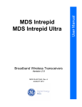
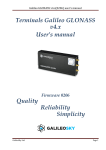
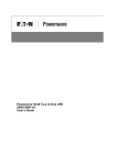
38190 Commercial Court
Slidell, LA U.S.A. 70458
Ph.(985)847-1104, Fax 1106
Email: [email protected]
WEB: www.outlandtech.com
PORTABLE
UNDERWATER VIDEO SYSTEM
MODEL UWS-3410
PAGE LEFT BLANK
38190 Commercial Court
Slidell, LA U.S.A. 70458
Ph.(985)847-1104, Fax 1106
Email:
[email protected]
UWS-3410
OPERATING INSTRUCTIONS
1. To operate Camera System, all interconnections from the Control
Unit, VCR & Monitor, should already be connected but in the
event there is a problem drawing # 0010550 shows how those
items connect.
CAUTION:
Insure voltage does not exceed 250 volts AC to
the Console. Also power source must be properly
grounded.
2. Power requirements, Typically 110 VAC to 250 VAC (50 or 60 Hz).
3. Plug Camera Umbilical into Camera and light (Be sure to use a
good quality silicon grease for lubrication). Plug topside
end of umbilical into Control Unit connector on front panel.
4. After verifying supply power is correct, insure camera, light
switches are in off position. Plug into power source.
5. Turn Monitor, Recorder and Camera switches on. A picture should
appear within a few secs.
6. Insure "Light Intensity" is at "Min" position. Turn light
switch on. Turn control up to test light. Turn back to Min.
and Turn switch off.
CAUTION:
" Light can be operated out of water but will
throttle back automatically if the temperature exceeds 50c.
However the Light will never shut off completely.
7. The CON-3400 console only outputs 28 VDC maximum.
8.) To Use the recorder please refer to the DVR manual.
Note:
Read the recorder manual for more details
concerning the operation of these recorders.
Outland Technology Inc.
38190 Commercial Ct.
Slidell, La. U.S.A. 70458
-1104, Fax (985)847-1106
EMAIL: [email protected]
Website: http://www.outlandtech.com
Any problems Please Contact:
QUICK START TO THE NEW DVR 883b
1) With camera and monitor connected, and on, push the DVR power button.
This takes about 30 secs, to show the main menu. Please wait.
2) To show the camera live, scroll down to “TV”, with the arrow keys and
push the center/enter arrow button to select.
3) If the camera and monitor are connected and on, a picture will appear
quickly.
4) To record, hit the “REC/stop” button and 4 lines will appear:
a. Path, could be C or USB (if a USB device is plugged into the front)
b. Memory size of drive plus how much is available.
c. Video Quality, High is normally selected. Med and low are available.
d. OK and Cancel.
5)
“C” is usually highlighted and if you want to record to the internal Hard
drive Just leave it alone.
6) Skip past video quality to OK and select enter (center) button.
7) The unit will start recording and a tiny red dot will appear on the bottom
left side of the screen indicating it is in record.
8) To stop, hit the “REC/stop” button again. It may take a few seconds to
actually say stop on the screen. It is closing the file and if it is large
enough may take 5-10 secs.
9) To playback the video hit the menu button and scroll up to “Recorded files”
Hit the select (center) button to select “Recorded files”.
10) Select which file to play by using the arrow buttons.
Hit the select (center) button to play.
11) To stop the playback hit the “Rec/stop” button.
For more detailed operation of this DVR see the manual supplied with the
system.
Once you get the video files to your computer see the folder VLC in the DVR
hard drive. Download it into your computer and use it to play and pull stills
from the video. This program is free to distribute and use.
OUTLAND TECHNOLOGY INC.
UWL-401 UNDERWATER LIGHT
Operating and Maintenance Procedures
Reference: DRAWING UWL-401
Installation and Operation:
A. The UWL-401, can be mounted to your Camera, ROV, Helmet or Hand
bracket by using DHM-60 OR HM-300 helmet bracket.
B. With Power Off, lubricate the light mating connector with a
light coating of silicon lubricant. Slide the locking sleeve of the
mating connector back. Align the raised dot on the connector with the
large connector pin on the light connector and plug in. Securely
tighten the locking sleeve.
THERE ARE NO USER SERVICEABLE PARTS INSIDE. PLEASE SEND BACK TO THE FACTORY FOR
SERVICE.
The only maintenance required is to flush with fresh water and dry for storage.
OUTLAND TECHNOLOGY INC.
38190 Commercial Court
Slidell, Louisiana U.S.A. 70458
Ph.(985)847-1104, Fax 1106
Email: [email protected]
Website: www.outlandtech.com
LIMITED WARRANTY
Outland has a strong commitment to high quality production. Each product has a twelve (12) month
limited warranty against defects in workmanship or materials with the exception of those outlined in the
limitations and exclusions. Outland will repair or replace at its discretion the defective components.
Limitations and Exclusions
• The limited warranty does not cover damage caused by improper use, poor maintenance or
accidental damage of the product or its components.
• The limited warranty does not cover items subject to wear including but not limited to view ports,
o-rings, umbilical, unless found to be defective in workmanship and/or materials.
• The limited warranty does not cover any modification made to these products without
authorization from Outland Technology Inc.
• The limited warranty does not cover lamps.
• The limited warranty does not cover components damaged due to incorrect power connection per
user’s manual.
• The limited warranty does not cover items not actually built by Outland. Example (DVD recorder,
Monitor etc.). That would be covered by the manufacturer's warranty.
Advertising claims made by us represent our honest opinion of the qualities and features offered by the
products described. We disclaim any warranties expressed or implied, including warranties of merchantability
and fitness for a particular purpose, except as provided herein. In no event shall Outland Technology be liable
for consequential damages of any kind.
Shipping
All returns for warranty service must be authorized by Outland. You must call or email Outland for a
RMA#. The assigned RMA (Returned Materials Authorization) number which must be clearly indicated
on each item returned for service.
NOTE: To submit a product or its components for warranty a RMA form must be completed.
Please complete as best and detailed as possible.
For warranty shipping within the first 30 days, Outland will pay for ground shipment on domestic orders
incoming and outgoing to a maximum of $75.00 each way. International shipments will be credited up to
$75.00 US for incoming and outgoing freight charges to Outland Technology Inc.
After 30 days the client is solely responsible for shipping to and from Outland Technology Inc.
During the first 30 days of the warranty period, should faster delivery service be requested, a $75.00 US
credit towards expedited freight for each applicable leg will be given.
If you have any questions regarding the installation and operation of this equipment, or if more
information is needed contact:
OUTLAND TECHNOLOGY,INC.,
38190 Commercial Ct.,Slidell, LOUISIANA USA 70458
(985)847-1104 FAX (985)847-1106
(Email) [email protected]
(Website) http://www.outlandtech.com
TROUBLESHOOTING GUIDE
CAMERA DOES
POWER CORD NOT
PLUGGED IN
NO
PLUG IN
NO
CONNECT
NO
TURN ON
YES
CAMERA
UMBILICAL NOT
PLUGGED IN AT
CONSOLE OR
YES
CAMERA POWER
SWITCH NOT ON.
YES
RECORDER NOT ON
OR IN PLAY MODE
NO
TURN ON/
YES
MONITOR NOT ON
NO
TURN ON
YES
CAMERA
DEFECTIVE
YES
TRY ANOTHER CAMERA.
NO
UMBILICAL HAS A
SHORT OR
BROKEN WIRES
YES
CHECK FOR
CONTINUNITY AND/OR
SHORTS USING
DRAWING #C-2303
YES
CHECK FOR 12-16 VDC
AT PINS B&C ON POWER
SUPPLY.
NO
CAMERA POWER
SUPPLY IS BAD.
LIGHT DOES NOT
POWER CORD NOT
NO
PLUG IN
YES
LIGHT UMBILICAL
NOT PLUGGED IN
AT CONSOLE OR
CAMERA
NO
CONNECT
YES
CHECK FOR
CONTINUNITY AND/OR
SHORTS USING
DRAWING #C-2303
YES
UMBILICAL HAS A
SHORT OR
BROKEN WIRES
12” TFT-LCD MONITOR
WITH
VIDEO INPUTS
288 Video Series
USER’S MANUAL
1. Control Functions
The monitor digital control functions are located on the front panel. They
are shown in the figure below and described in the following paragraphs.
1.
Power indicator LED
2.
Power switch
3.
Function keys
Function Selection
1. Press the knob “MENU/SELECT” to show the OSD menu. Then use the
“▲” and “▼” to select a function. Press the knob “AUTO/EXIT” to close
the OSD menu.
2. With the knob “▲” and “▼” , you can adjust the speaker volume on the
monitor.
When you press the “▼”, the speakers are mute. Press the “▲” and
then the speakers are active.
When you press the knob “▲” , the speaker volume OSD is shown.
You can increase or decrease the volume by pressing the “▲” and
“▼”.
3. You can hold the knob “AUTO/EXIT” for more than 1 second to adjust the
image quality automatically.
The OSD menu will close automatically after 3-10 seconds without operation
and saves any changes you have made.
Function Adjustments
1. Signal Select
When there is no OSD menu display the knob “AUTO/EXIT” can select
VGA / DVI / CVBS / S-VIDEO.
2. Video
Contrast
- Adjust the difference in luminance between light and dark
areas of the image.
Brightness
- Adjust the luminance level of the image.
Colour
- Adjust the Color level of the image
Tint
- Adjust the Tint level of the image
Sharpness
- Adjust the Sharpness level of the image
Video Mode
- Adjust the Video Mode for
Normal/Nature/Cinema/Sport/Vivid
Reset
- Recall the factory setting of the Vide menu.
VGA
Contrast
- Adjust the difference in luminance between light and dark
areas of the image.
Brightness
- Adjust the luminance level of the image.
8
Sharpness
- Adjust the Sharpness level of the image
Color Temperature - Adjust Color Temperature
Cool(9300k)/User/Warm(6500k)/Nature(7500k)
User RGB
- Adjusting R/G/B level of the image
9
Image
Auto Tune - Adjust geometry of the image automatically.
Position
- Adjust the vertical & horizontal position of the image.
Phase
Clocks
- Adjust the horizontal sync phase of signal.
- Adjust the horizontal sync size of signal.
Reset
- Recall the factory setting of the VGA menu.
3. Audio (Video & VGA)
Volume
- Adjust the speaker volume.
4. Feature Controls (Video & VGA)
Sleep Timer
- Select 10/20/30/40/50/60/70/80/90/Off
Language
-Select Language
English/Fran/Deu/Esp/Ita
OSD Controls
Factory Recall
-Select OSD Position /Rotation/Timer
- Recall Factory setting
2. Product Specifications
7.1 288V series product specifications
Features
Model
Panel Type:
Screen Size:
Pixel Pitch:
Brightness:
Contrast Ratio:
Response Time:
Viewing Angle(H / V)
Max. Resolution:
Display Color
Video Input
Display Area
288V Series
Active TFT-LCD
12” diagonal
0.3075 (W) x 0.3075 (H) mm
Typical: 400 cd/㎡
Typical: 500:1
Typical: 35 ms
Typical: 140° / 110°
800 (W) x 600 (H)
262 K
Analog:15-pin, D-sub connector x1
S-Video x1, RCA composite x1
Digital: DVI connector (optional)
9.7 (W) x 7.2 (H) inch
[246 (W) x 184 (H) mm]
Input voltage:
Output rating:
Power Consumption
100-240V /60-50Hz
12V DC, 2.0A
25 watts (max.), 3 watts (standby)
Audio
1.0 watts x 1 built-in speaker
RCA composite x1
Frequency
Horizontal:30-47 KHz; Vertical: 50-75 Hz
Dimensions(set size)
13.4 (H) x 14.4 (W) x 7.7 (D) inch
[340(H) x 365(W) x 195(D) mm]
Safety & EMI
UL, CUL, FCC-B, CB, CE, TUV/GS
Weight
N.W.: 6.6 lbs (3.0 Kgs)
G.W.: 7.9 lbs (3.6 Kgs)
Operating Conditions
5°C – 35°C; 20%-80% RH
Storage Conditions:
-20°C – 60°C; 10%-90% RH
Wall mountable
Yes, VESA 75 bracket
The typical value of brightness, contrast ratio, response time and viewing angle is subject to change
without notice.
DVR 883B
V3.0
PRECAUTIONS
- Ensure power is turned off while making all cable connections to the DVR.
- Never turn off the unit during a firmware upgrade. If this happens, the DVR may be
irreparably damaged, and the warranty may void.
- The DVR 883B is designed to automatically enter sleep mode when rear USB cable is
connected. This is not a fault condition.
- Have the DVR checked by a qualified technician if:
- The power supply or plug appear to be damaged
- An external object or liquid enter the unit
- The unit does not function properly
- The unit has been dropped or the cover has been damaged
DO NOT OPEN THE COVER AND/OR ATTEMPT TO REPAIR THE UNIT YOURSELF!
FEATURES
Video Recording Function
This DVR can record live video at DVD quality (D1 resolution, 720x576/720x480), with standard
MPEG-4 encoding and AVI file container. This recorded AVI can be played back using Windows
Media Player without additional plug-in. They can also be played back using VLC Media Player
software that is pre-installed on the DVR’s HDD.
Connectivity and Storage
File System – Supports NTFS (read and write. No partition or file size limitation.) USB 2.0 Client.
After connecting to a PC through USB interface the user can exchange files from the hard drive
to a PC through the USB 2.0 port on the rear of the unit and the included USB cable.
USB 2.0 Host – The front USB port supports external USB devices including USB HDD, FlashDisk, Card Reader, etc. The user can connect these devices to the DVR 883B and record video
directly to them instead of the internal HDD.
DESCRIPTION OF CONTROLS
Front Panel:
1
2
3
4
5
6
7
8
9
10
11
12
Power on/off
Record/Stop
Home Menu
Power indicator
Left/Preview
Enter
Up
Right/Function
Down
Infrared
receiver
SD card reader
USB HOST
Rear Panel:
1
2
3
4
Power jack
(12vdc)
USB connect
AV Input
AV Output
MENUS
When you turn on the DVR 883B, it will display the
welcome screen as shown. It takes several seconds for
the DVR to boot up, so be patient!
If you have a USB or SD device connected to the front
panel, a window will pop up at this time, acknowledging that the DVR recognizes this device
and it is available for use. Additionally, the corresponding icon will be highlighted in the bottom
left corner of the screen.
The HOME screen displays the main menus: ALL FILES, TV, RECORDED FILE, AND SETTING. The
user can scroll through these menus using the remote or front panel control “UP” and “DOWN”
keys to choose the appropriate menu. Pressing the “LEFT” key will back you out of any of the
sub-menus, and return you to the HOME screen.
ALL FILES
When you enter the ALL FILES menu, it will display all available devices/drives. Press UP,
DOWN or OK to access the drive you want, or press LEFT to return to the previous menu screen.
In the ALL FILES menu, you can play files from all connected devices. Also, you can transfer files
from one drive to another. This will be covered later in the manual.
TV
The DVR 883B has a very powerful recording function. It can record AV input to the internal
HDD, or to a selected USB or SD device. This is accomplished by entering the TV mode from the
home menu screen.
If you have the Camera cable connected to the Outland console, and it is switched on, the
screen will display live video from TV mode. If there is no AV signal to the DVR, the screen will
appear black. Pressing the MENU button will return you to the HOME menu screen from TV
mode.
When you want to record, press the “RECORD” button. The menu below will be displayed:
RECORDING SETTINGS Block:
“REC PATH” selects where the data is saved. The user can save data to “C” (internal HDD), SD
Card or USB device. NOTE: When saving data to SD or USB device, do not remove the device
when data is saving.
“MEMORY SPACE” shows available memory for recording.
“REC QUALITY” allows selection of HIGH, MEDIUM, or LOW video resolution quality. Outland
Technology recommends using only the HIGH quality setting for best results.
Once you verify the settings are correct, press “OK” to start recording. A red dot will appear at
the bottom left of the screen, and will remain there as long as the unit is recording video.
Press “STOP” to stop recording. Once you are finished recording, pressing the MENU button
will take you back to the home menu.
COPYING VIDEO FROM HDD TO SD OR USB DEVICE
Copying video from the internal HDD to an SD or USB device is accomplished by first entering
the ALL FILES menu, RECORDED FILE folder. Once you find the file or folder you wish to copy,
highlight this item and press the RIGHT key. It will display as below. Arrow down to SELECT or
copy one file or folder.
SELECT ALL (copy all): selects all files within a given folder.
PASTE: Once you have chosen the file(s) you wish to copy, and have SELECTED them, LEFT
arrow back to the ALL FILES menu, and select the device you wish to copy to. Once you have
opened the device you wish to copy to, right arrow and select PASTE from the drop down
menu.
SETTINGS
The DVR has been factory set for the best settings. However, should you need to make
adjustments to them, the basic functions are described below.
SYSTEM SETUP:
-Menu Language: Supports English and Chinese
-Skin Type: User can select a blue or black color theme for menus
-Current Time: Allows user to reset date and time
-Default Setting: Will restore all settings to factory. This is not recommended unless directed by
Outland Technology Tech Support Staff.
VIDEO SETUP:
-TV system: Select between PAL and NTSC video systems
- Aspect Ratio: can choose 16:9 or 4:3
RECORDING SETUP:
-Allows user to choose High/Med/Low resolution.
SPECIFICATIONS
Features:
•
D1 resolution at 704*576. DVD picture quality up to 500 TV line.
•
Video format: MPEG4/AVI, audio format: MP3
•
30 frame per second
•
AV out supported
•
Support Mpeg4/AVI FILE
Parameter:
Video Format, Mpeg -4, Video for ASF
Resolution, 704*576, 640*576, 320*288
Frame,
30f/s
Video input, 1V,75Ω
Video output, 1V,75Ω
Memory
Media SD/ SDHC Card for 32GB (not included)
500 G HARD DRIVE INCLUDED.
Power
Electricity Input
Working electricity
Power expend
<2A
<24W
Language
English, Simple Chinese
DC 12V
APPENDIX A:
5100A/I VIDEO TYPEWRITER OPTION:, TIME/DATE AND TEXT on screen,
A. The Video typewriter powers up whenever the console is
plugged in. The video always goes through the Video
typewriter
B. After powering on the system the screen should go to page
zero "0". Anything in page zero will be displayed as well as
time and date, if it were on the screen when it was powered
off.
C. Hit the “H” Key and the main menu will appear on the
screen.
D. Menu:
(KEY)(FUNCTION)
E
EDIT PAGE 0
C
CLEAR PAGE 0
T
TIME OFF
D
DATE OFF
S
SET TIME
R
RESET SYSTEMS
P
SCALE (Ruler)
X
Cross Hair (Pointer)
I
SET INTENSITYN
N
Camera Mode
1) E; Go to the Page you want to edit by touching the
number key. Touch the letter “E”. This will bring you
into the edit mode and you should see a Blinking cursor
at the top left corner of the screen. Type in anywhere
on the screen and when you finish hit the “ESC” key.
The text will store in memory and the cursor will
disappear.
2) C; Go to the page you want to clear and hit the
letter C. The following will appear:
ARE YOU SURE YOU WANT TO
CLEAR PAGE 0 ? (Y/N)
This will clear the page of all characters except the
time and date. Select yes or no.
3) T; Hitting this key will turn the time either on or
off.
4) D; Hitting this key will turn the date either on or
off.
5) S; Hitting this key will allow you to set the time
and date. The following will appear:
( 12,51,5,21,99)
ENTER HR,MIN,MONTH,DAY,YEAR
Input the time and date as shown with comas
between each item followed by "ENTER".
6) R; Hitting this key will clear all pages. The
following will appear:
ARE YOU SURE YOU WANT TO
CLEAR ALL MEMORY ? (Y/N)
Select yes or no. The time and date
screen.
will remain on
7) P; Hitting this key will cause the Video Ruler to
appear on the bottom of the screen. The Video
typewriter time date features will continue to operate.
The active keys to use this feature are:
“O”, sets scale factor. 1=1, 2=2, 3=3, etc. for every
tic mark. Minus for tic marks to the left and
+ for each tic mark to the right. The digital
Display below and to the left of the scale is
where on the Ruler the cursor marker is in
relation to the center of the scale.
“Left Arrow” Key moves the cursor to the left on the
ruler.
“Right Arrow” Key moves the cursor to the right on the
ruler. The digital display moves up and down as
these arrow keys are used.
“Home” Key moves the ruler tic marks wider.
“End” Key moves the ruler tic marks closer.
“Page Down” moves the center (offset) of the ruler
Left.
“Page Up” moves the center (offset) of the ruler Right.
To use this feature set the scale factor for the
required measurement. Move the center (offset) of
ruler to the center of the item to be measured. A
reference must be used to accurately measure with
Video Ruler. If Laser dots are use then scale the
to those dots. Once the ruler is scaled using the
the
the
ruler
“end”
and “Home” Keys, use the arrow key to show the
measurement.
8) X; Hit this key and a Crosshair will appear on
Screen. Use the cursor keys to move the crosshair
(Video Pointer) around the screen. In this mode the
Scale will disappear. The time and date will remain on
Screen and all page functions will work also.
9) I; Hitting this key will bring up the following:
SET INTENSITY LEVEL
0 MIN, 15 MAX >
Default is 3. If you enter 0 then the characters will
turn black. If 14 or 15 are entered then the character
will probably be a little too bright. Play around with
this and set for best display.
10) N; Hit this key and the camera control menu will
appear. This is for controlling multiple cameras. If
you only have one camera connected and it is a fixed
focus camera disregard this function.
IF AT ANY TIME THE VIDEO TYPEWRITER LOCKS UP, THE
SYSTEM CAN BE RESET BY UNPLUGGING THE CONSOLE FROM THE
POWER SOURCE. SIMPLY TURNING THE CAMERA, MONITOR AND DVR
OFF WILL NOT WORK.