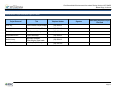
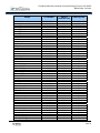
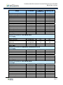
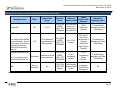
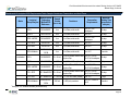
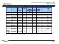
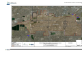
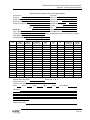
1
FINAL BROWNFIELDS ENVIRONMENTAL CONSULTANT/TESTING SERVICES UNIFORM FEDERAL POLICY-QUALITY ASSURANCE PROJECT PLAN CITY OF WHEAT RIDGE, COLORADO Prepared for: City of Wheat Ridge 7500 West 29th Avenue Wheat Ridge, Colorado 80033 Prepared by: RMC Consultants, Inc. 12295 West 48th Avenue Wheat Ridge, Colorado 80033 January 2014 Final Brownfields Environmental Consultant/Testing Services UFP-QAPP City of Wheat Ridge, Colorado TABLE OF CONTENTS 1.0 PROJECT MANAGEMENT AND OBJECTIVES: WORKSHEETS 1-16 Worksheet #1 Title And Approval Page .......................................................... 8 Worksheet #2 Qapp Identifying Information .................................................... 9 Worksheet #3 Distribution List ...................................................................... 14 Worksheet #4 Project Personnel Sign-Off Sheet .......................................... 15 Worksheet #5 Project Organizational Chart .................................................. 16 Worksheet #6 Communication Pathways ..................................................... 17 Worksheet #7 Personnel Responsibilities And Qualifications ....................... 18 Worksheet #8 Special Personnel Training Requirements ............................. 19 Worksheet #9 Project Scoping Session Participants Sheet .......................... 20 Worksheet #10 Problem Definition................................................................ 21 Worksheet #11 Project Quality Objectives/Systematic Planning Process Statements ............................................................ 22 Worksheet #12 Measurement Performance Criteria ..................................... 24 Worksheet #13 Secondary Data Criteria and Limitations.............................. 26 Worksheet #14 Summary of Project Tasks ................................................... 27 Worksheet #15 Reference Limits And Evaluation Table ............................... 29 Worksheet #16 Project Schedule Timeline ................................................... 43 2.0 MEASUREMENT AND DATA ACQUISITION: WORKSHEETS 17-30 Worksheet #17 Sampling Design And Rationale .......................................... 44 Worksheet #18 Sampling Locations and Methods/SOP Requirements Table ................................................................................... 45 Worksheet #19 Analytical SOP Requirements Table .................................... 46 Worksheet #20 Field Quality Control Sample Summary Table ..................... 47 Worksheet #21 Project Sampling SOP References Table ............................ 48 Worksheet #22 Field Equipment Calibration, Maintenance, Testing, and Inspection Table ........................................................... 49 Worksheet #23 Analytical SOP References Table ........................................ 51 Worksheet #24 Analytical Instrument Calibration Table................................ 53 Worksheet #25 Analytical Instrument And Equipment Maintenance, Testing, and Inspection Table ............................................. 58 Worksheet #26 Sample Handling System ..................................................... 59 Worksheet #27 Sample Custody Requirements ........................................... 60 Page ii Final Brownfields Environmental Consultant/Testing Services UFP-QAPP City of Wheat Ridge, Colorado Worksheet #28 QC Samples Table............................................................... 61 Worksheet #29 Project Documents and Records Table ............................... 64 Worksheet #30 Analytical Services Table ..................................................... 65 3.0 ASSESSMENT AND OVERSIGHT WORKSHEETS 31-33 Worksheet #31 Planned Project Assessments Table ................................... 66 Worksheet #32 Assessment Findings and Corrective Action Responses ..... 67 Worksheet #33 Qa Management Reports Table ........................................... 68 4.0 DATA REVIEW WORKSHEETS 34-37 Worksheet #34 Verification (Step I) Process Table....................................... 69 Worksheet #35 Validation (Steps IIa And IIb) Process Table ....................... 70 Worksheet #36 Validation (Steps IIa And IIb) Summary Table ..................... 71 Worksheet #37 Usability Assessment ........................................................... 72 Page iii Final Brownfields Environmental Consultant/Testing Services UFP-QAPP City of Wheat Ridge, Colorado LIST OF FIGURES Figure 1 Wheat Ridge Urban Renewal Area Assessment Map LIST OF APPENDICES Appendix A Standard Operating Procedures (SOPs) Page iv Final Brownfields Environmental Consultant/Testing Services UFP-QAPP City of Wheat Ridge, Colorado LIST OF ACRONYMS ACM ASTM AAI bgs BTEX CDPHE CPR CAS CCC CCV CERCLA COC CSM DO DoD DQO DRO EDD EPA ESA FSP GRO GC/MS HAZWOPER HCL ICAL ICV ID IDW LBP LCS LOD LOQ MDL mL Asbestos-Containing Material American Society for Testing and Materials All-Appropriate-Inquiry below ground surface benzene, toluene, ethylbenze and xylene Colorado Department of Public Health and Environment Cardiopulmonary Resuscitation Chemical Abstract Service Registry Number Calibration Check Compound Continuing Calibration Verification Comprehensive Environment Response, Compensation, and Liability Act Chain-of-Custody Conceptual Site Model Dissolved Oxygen Department of Defense Data Quality Objective Diesel Range Organics Electronic Data Deliverable U.S. Environmental Protection Agency Environmental Site Assessment Field Sampling Plan Gasoline Range Organics Gas Chromatograph/Mass Spectrometer Hazardous Waste Operations and Emergency Response Hydrochloric Acid Initial Calibration Initial Calibration Verification Identification Investigation Derived Waste Lead-Based Paint Laboratory Control Sample Limit of Detection Limit of Quantitation Method Detection Limit milliliter Page v Final Brownfields Environmental Consultant/Testing Services UFP-QAPP City of Wheat Ridge, Colorado MS/MSD mS/cm MTBE NA NELAP ND NTU ORP OSHA PM ppm PQO QA QAPP QC QSM RCRA RF RFP RL RMC RPD RSD SEDD SOP SPCC SSHO SSHP Std SVOC SW TOD TPH UFP VOA VOC VOA VOC Matrix Spike/Matrix Spike Duplicate milliSiemens per centimeter methyl tert-butyl ether Not Applicable National Environmental Laboratory Accreditation Program Non-detect Nephelometric Turbidity Units Oxidation-Reduction Potential Occupational Safety & Health Administration Project Manager parts per million Project Quality Objectives Quality Assurance Quality Assurance Project Plan Quality Control Quality Systems Manual Resource Conservation and Recovery Act Response Factor Request for Proposals Reporting Limit RMC Consultants, Inc. Relative Percent Difference Relative Standard Deviation Staged Electronic Data Deliverable Standard Operating Procedure System Performance Check Compound Site Safety and Health Officer Site Safety and Health Plan Standard Semi-Volatile Organic Carbon Solid Waste Transit Oriented Development Total Petroleum Hydrocarbons Uniform Federal Policy Volatile Organic Analyte Volatile Organic Compound Volatile Organic Analysis Volatile Organic Compound Page vi Final Brownfields Environmental Consultant/Testing Services UFP-QAPP City of Wheat Ridge, Colorado WR2020 µg/L % Wheat Ridge 2020 microgram per liter Percent Page vii Final Brownfields Environmental Consultant/Testing Services UFP-QAPP City of Wheat Ridge, Colorado WORKSHEET #1 TITLE AND APPROVAL PAGE Site Name/Project Name: Wheat Ridge, Colorado Community-Wide Brownfields Assessment Project Site Location: Site locations will consist of properties located at Kipling and 38th Avenue, and 49th Avenue and Ward Road [future transit oriented development (TOO) site for the end-of-the-line station for the Gold Line light rail system], and Wheat Ridge urban renewal areas, including properties along the Wadsworth Boulevard corridor between 35th Avenue and 44th Avenue and at 44th Avenue and Ward Road (Figure 1). Document Title: Uniform Federal Policy-Quality Assurance Project Plan (UFP-QAPP) for Brownfields Environmental Consultant/Testing Services, City of Wheat Ridge, Colorado Lead Organization: City of Wheat Ridge, Colorado Preparer's Name and Organization, Address, Telephone Number, and E-mail Address: Jennifer Hussey- RMC Consultants, Inc.; 12295 West 48th Avenue, Unit A, Wheat Ridge, CO, 80033; 303.980.4101; [email protected] Revision Preparation Date (Day/Month/Year): Initial submittal Investigative Prf!iect Manager: David Groy!RMC Consultants ~ /. df..;x:>l'/-- /7// si~at\e/0~ Project Field Operations Manager: Claude Murray!RMC Consultant~&; rP )1 9 Signature/Date Lead Organization's Project Manager: Sally Payne, City of Wheat Ridge _ _ _ __ __ _ _ Signature/Date Appro~t ___ __ _ _ __ _ _ __ _ __ _ __ _ __ _ _ _ __ __ Signature/Date PrinredName!Tftm: _________________________________________________ Approval' _ _ _ __ _ __ __ _ __ _ __ _ __ _ _ _ __ __ _ Signature/Date PrinredName!Tftm: ___________________________________________________ • RMC tell'•'liA~•I Page 8 Final Brownfields Environmental Consultant/Testing Services UFP-QAPP Wheat Ridge, Colorado WORKSHEET #2 QAPP IDENTIFYING INFORMATION Site Name/Project Name: Wheat Ridge, Community-Wide Brownfields Assessment Project Colorado Title: UFP-QAPP for Brownfield Environmental Consultant/Testing Services Site Location: Properties located at Kipling and 38th Avenues, 49th Revision Number: 0 Avenue and Ward Road, (future TOD site for the Gold Line terminal), and Wheat Ridge urban renewal areas, including properties along the Wadsworth Boulevard corridor between 35th and 44th Avenues, and at 44th Avenue and Ward Road (Figure 1). Site Number/Code: NA Revision Date: NA Operable Unit: NA Contractor Name: RMC Consultants, Inc. Contractor Number: RFP No. 13-11 Contract Title: Brownfields Enviromental Consultants/Testing Services Agreement 1. Identify regulatory program: Work performed shall follow the standards for Phase II environmental site assessments (ESAs) established by the American Society for Testing and Materials (ASTM) to address the “All-Appropriate-Inquiry” (AAI) aspect to the Comprehensive Environment Response, Compensation, and Liability Act (CERCLA). Specifically, all work performed shall follow the guidance outlined in ASTM Standard E1903-97R02, Guide for Environmental Site Assessments: Phase II Environmental Site Assessment Process. Completion of Phase II work will also be consistent with the requirements of the Colorado Voluntary Cleeanup Program evaluation criteria for soil (e.g., risk-based guidance: Colorado Soil Evaluation Values) and water (i.e., Colorado state surface and ground water standards), where applicable. 2. Identify approval entity: City of Wheat Ridge with support from Wheat Ridge 2020 (WR2020) and the Environmental Protection Agency (EPA) Region 8 3. The QAPP is (select one): Generic Project Specific 4. List dates of scoping sessions that were held: NA 5. List dates and titles of QAPP documents written for previous site work, if applicable: Title Approval Date NA 6. List organizational partners (stakeholders) and connection with lead organization: WR2020, a community and economic development organization in partnership with the City of Wheat Ridge, and the EPA Region 8. 7. List data users: City of Wheat Ridge, WR2020, EPA, and RMC Consultants, Inc. (RMC) 8. Document Control Numbering System: A document control numbering system will not be used; QAPP recipients are listed on Worksheet #3. Page 9 Final Brownfields Environmental Consultant/Testing Services UFP-QAPP Wheat Ridge, Colorado Worksheet #2 QAPP Identifying Information Required QAPP Element(s) and Corresponding QAPP Section(s) Required Information Crosswalk to Related Documents Project Management and Objectives 2.1 Title and Approval Page – Title and Approval Page Worksheet #1 2.2 Document Format and Table of Contents 2.2.1 Document Control Format 2.2.2 Document Control Numbering System 2.2.3 Table of Contents 2.2.4 QAPP Identifying Information – Table of Contents – QAPP Identifying Information Worksheet #2 2.3 Distribution List and Project Personnel Sign-Off Sheet 2.3.1 Distribution List 2.3.2 Project Personnel Sign-Off Sheet – Distribution List – Project Personnel Sign–Off Sheet Worksheet #3 Worksheet #4 2.4 Project Organization 2.4.1 Project Organizational Chart 2.4.2 Communication Pathways 2.4.3 Personnel Responsibilities and Qualifications 2.4.4 Special Training Requirements and Certification – Project Organizational Chart – Communication Pathways – Personnel Responsibilities and Qualifications Table – Special Personnel Training Requirements Table Worksheet #5 Worksheet #6 Worksheet #7 Worksheet #8 2.5 Project Planning/Problem Definition – 2.5.1 Project Planning (Scoping) 2.5.2 Problem Definition, Site History, and – Background Project Planning Session Worksheet #9 Documentation (including Data Needs tables) Project Scoping Session Participants Sheet – Problem Definition, Site History, and Worksheet #10 Background – Site Maps (historical and present) 2.6 Project Quality Objectives and Measurement Performance Criteria 2.6.1 Development of Project Quality Objectives Using the Systematic Planning Process 2.6.2 Measurement Performance Criteria – Site–Specific PQOs – Measurement Performance Criteria Table Worksheet #11 Worksheet #12 Page 10 Final Brownfields Environmental Consultant/Testing Services UFP-QAPP Wheat Ridge, Colorado Required QAPP Element(s) and Corresponding QAPP Section(s) 2.7 Required Information Secondary Data Evaluation 2.8 Project Overview and Schedule 2.8.1 Project Overview 2.8.2 Project Schedule Crosswalk to Related Documents Sources of Secondary Data and Information – Secondary Data Criteria and Limitations Table Worksheet #13 Summary of Project Tasks – Reference Limits and Evaluation Table – Project Schedule/Timeline Table Worksheet #14 Worksheet #15 Worksheet #16 Measurement/Data Acquisition 3.1 Sampling Tasks 3.1.1 Sampling Process Design and Rationale 3.1.2 Sampling Procedures and Requirements 3.1.2.1 Sampling Collection Procedures 3.1.2.2 Sample Containers, Volume, and Preservation 3.1.2.3 Equipment/Sample Containers Cleaning and Decontamination Procedures 3.1.2.4 Field Equipment Calibration, Maintenance, Testing, and Inspection Procedures 3.1.2.5 Supply Inspection and Acceptance Procedures 3.1.2.6 Field Documentation Procedures 3.2 Analytical Tasks 3.2.1 Analytical SOPs 3.2.2 Analytical Instrument Calibration Procedures 3.2.3 Analytical Instrument and Equipment Maintenance, Testing, and Inspection Procedures 3.2.4 Analytical Supply Inspection and Acceptance Procedures Sampling Design and Rationale – Sample Location Map – Sampling Locations and Methods/SOP Requirements Table – Analytical Methods/SOP Requirements Table – Field Quality Control Sample Summary Table – Sampling SOPs – Project Sampling SOP, References, Table Field Equipment Calibration, Maintenance, Testing, and Inspection Table Worksheet #17 Analytical SOPs – Analytical SOP References Table – Analytical Instrument Calibration Table – Analytical Instrument and Equipment Maintenance, Testing, and Inspection Table Worksheet #23 Worksheet #18 Worksheet #19 Worksheet #20 Worksheet #21 Worksheet #22 Worksheet #24 Worksheet #25 Page 11 Final Brownfields Environmental Consultant/Testing Services UFP-QAPP Wheat Ridge, Colorado Required QAPP Element(s) and Corresponding QAPP Section(s) Required Information Crosswalk to Related Documents 3.3 Sample Collection Documentation, Handling, Tracking, and Custody Procedures 3.3.1 Sample Collection Documentation 3.3.2 Sample Handling and Tracking System 3.3.3 Sample Custody – Sample Collection Documentation Handling, Tracking, and Custody SOPs – Sample Container Identification – Sample Handling Flow Diagram – Example Chain-of-Custody Form and Seal Worksheet #26 Worksheet #27 3.4 Quality Control Samples 3.4.1 Sampling Quality Control Samples 3.4.2 Analytical Quality Control Samples – QC Samples Table – Screening/Confirmatory Analysis Decision Tree Worksheet #28 3.5 Data Management Tasks 3.5.1 Project Documentation and Records 3.5.2 Data Package Deliverables 3.5.3 Data Reporting Formats 3.5.4 Data Handling and Management 3.5.5 Data Tracking and Control – Project Documents and Records Table – Analytical Services Table – Data Management SOPs Worksheet #29 Worksheet #30 Assessment/Oversight 4.1 Assessments and Response Actions 4.1.1 Planned Assessments 4.1.2 Assessment Findings and Corrective Action Responses – 4.2 QA Management Reports – – – – Assessments and Response Actions Planned Project Assessments Worksheet #31 Table Audit Checklists Worksheet #32 Assessment Findings and Corrective Action Responses Table QA Management Reports Table Worksheet #33 4.3 Final Project Report Page 12 Final Brownfields Environmental Consultant/Testing Services UFP-QAPP Wheat Ridge, Colorado Required QAPP Element(s) and Corresponding QAPP Section(s) Required Information Crosswalk to Related Documents Data Review 5.1 Overview 5.2 Data Review Steps 5.2.1 Step I: Verification 5.2.2 Step II: Validation 5.2.2.1 Step IIa Validation Activities 5.2.2.2 Step IIb Validation Activities 5.2.3 Step III: Usability Assessment 5.2.3.1 Data Limitations and Actions from Usability Assessment 5.2.3.2 Activities 5.3 Streamlining Data Review 5.3.1 Data Review Steps to be Streamlined 5.3.2 Criteria for Streamlining Data Review 5.3.3 Amounts and Types of Data Appropriate for Streamlining – – – – Verification (Step I) Process Table Validation (Steps IIa and IIb) Process Table Validation (Steps IIa and IIb) Summary Table Usability Assessment NA Worksheet #34 Worksheet #35 Worksheet #36 Worksheet #37 NA Page 13 Final Brownfields Environmental Consultant/Testing Services UFP-QAPP Wheat Ridge, Colorado Worksheet #3 Distribution List QAPP Recipients Title Organization Telephone Number Fax Number E-mail Address Document Control Number Sally Payne Senior Planner and Project City of Wheat Ridge Manager (303) 235-2852 (303) 234-2857 [email protected] Not Applicable Bill Rothenmeyer Brownfield Project Manager U.S. EPA Region 8 (303) 312-6045 (303) 312-6065 [email protected] Not Applicable David Groy Prime Contractor Project Manager RMC (303) 980-4101 (303) 980-4107 [email protected] Not Applicable Jason Kahlert Project Health & Safety Officer RMC (303) 980-4101 (303) 980-4107 [email protected] Not Applicable Claude Murray Field Operations Manager RMC (303) 980-4101 (303) 980-4107 [email protected] Not Applicable RMC (303) 980-4101 (303) 980-4107 [email protected] Not Applicable Joseph Mastromarchi Project QA Manager Jennifer Hussey Site Health & Safety Officer/ Sampling Team Leader RMC (303) 980-4101 (303) 980-4107 [email protected] Not Applicable Noelle Doyle Mathis Laboratory Project Manager Origin Laboratory, Inc. (303) 433-1322 (303) 265-9645 [email protected] Not Applicable Note: The Project Manager, Mr. David Groy, will distribute the QAPP electronically to all QAPP recipients listed in table. Page 14 Final Brownfields Environmental Consultant/Testing Services UFP-QAPP Wheat Ridge, Colorado Worksheet #4 Project Personnel Sign-Off Sheet Project Personnel Title Telephone Number David Groy Prime Contractor Project Manager (303) 980-4101 Jason Kahlert Project Health & Safety Officer (303) 980-4101 Claude Murray Field Operations Manager (303) 980-4101 Joseph Mastromarchi Project QA Manager (303) 980-4101 Jennifer Hussey Site Safety and Health Officer/Sampling Team Leader (303) 980-4101 Noelle Doyle Mathis Laboratory Project Manager (303) 433-1322 Signature Date Quality Assurance Project Plan Read Page 15 Final Brownfields Environmental Consultant/Testing Services UFP-QAPP Wheat Ridge, Colorado Worksheet #5 Project Organizational Chart Regulatory Stakeholder: EPA Region 8 Bill Rothenmeyer RMC Representative: Jason Kahlert, Health & Safety Officer Reviews Health & Safety protocol/practices, prepares SSHP, and ensures H & S training/ certification is obtained by site personnel. Lead Organization and Approval Authority: City of Wheat Ridge Sally Payne, Sr. Planner, AICP Contractor Organization: RMC Consultants, Inc. David Groy, Project Manager Manages environmental tasks and coordinates with lead agency and subcontractors. RMC Representative: Jennifer Hussey, Sampling Team Leader Leads the field sampling effort, reports any deviations from the FSP, and provides health & safety and QA/QC oversight. Subcontractor Organization: Origins Laboratory, Inc. Noelle Doyle Mathis Stakeholder: WR2020 Denise Balkas RMC Representative: Claude Murray, Field Operations Manager Coordinates all field activities and will notify Project Manager of changes to QAPP and FSP. RMC Representative: Joseph Mastromarchi, Project QA Manager Provides QA/QC oversight, reviews data, evaluates the need for corrective actions, and maintains the approved QAPP. Subcontractor Organization: Remington Technologies, LLC (Drilling) Jesse Taylor Line of Authority Line of Communication Page 16 Final Brownfields Environmental Consultant/Testing Services UFP-QAPP Wheat Ridge, Colorado Worksheet #6 Communication Pathways Communication Drivers Responsible Entity Name Phone Number Procedure Principal Point of Contact with EPA, WR2020, and RMC, Inc. Lead Organization Project Manager Sally Payne (303) 235-2852 All materials and information about the project will be forwarded to EPA and WR2020 by Sally Payne. Manage all Project Phases Involving Environmental Tasks Project Manager David Groy (303) 980-4101 RMC liaison to Sally Payne. QAPP changes in the field Field Operations Manager Claude Murray (303) 980-4101 Mr. Murray will notify David Groy of changes to QAPP made in the field. Reporting Lab Data Quality Issues Laboratory Quality Assurance Officer Noelle Doyle Mathis (303) 433-1322 All laboratory quality assurance/quality control (QA/QC) issues will be reported by Noelle Doyle Mathis to Joseph Mastromarchi as soon as lab becomes aware of problem. Field and Analytical Corrective Actions Project QA Manager Joseph Mastromarchi (303) 980-4101 The need for corrective action for field and analytical issues will be determined by Joseph Mastromarchi. Release of Analytical Data Project QA Manager Joseph Mastromarchi (303) 980-4101 No analytical data can be released until data verification is completed and Joseph Mastromarchi has approved the release. QAPP Amendments Approval Authority Project Manager Sally Payne (303) 235-2852 Any major changes to the QAPP must be approved by Sally Payne before the changes can be implemented. Page 17 Final Brownfields Environmental Consultant/Testing Services UFP-QAPP Wheat Ridge, Colorado Worksheet #7 Personnel Responsibilities and Qualifications Name Title Organizational Affiliation Responsibilities Education and Experience Qualifications Sally Payne Project Manager City of Wheat Ridge Oversees project and responds to regulatory agency American Institute of Certified Planners (AICP) certification David Groy Project Manger RMC Manages environmental tasks coordinates with Lead Agency Master of Science, Environmental Policy and Management, 30 yrs. exp. RMC Leads the field sampling effort as necessary and provides Quality Assurance/Quality Control oversight Bachelor of Science/Master of Arts, Geology, 16 yrs. exp. Jennifer Hussey Jason Kahlert Sampling Team Leader Project Health and Safety Officer RMC Reviews Health and Safety protocols and practices, responsible for ensuring Bachelor of Science, Geology, 19 yrs. exp. OSHA-required H & S training and State-required asbestos certification obtained for applicable site personnel Joseph Mastromarchi Project QA Manager RMC Maintains the official, approved QAPP, reviews data and QA/QC procedures, and verifies that corrective action is taken Bachelor of Science, Geology, 24 yrs. exp. when necessary. The Project QA Manager position is independent of the unit generating data. Claude Murray Field Operations Manager RMC Coordinates all field activities and provides Quality Assurance/Quality Control oversight. Provides health and safety oversight, acts as backup Site Safety and Health Officer Noelle Doyle Mathis Laboratory Project Manager Origins Laboratory, Inc. Manages laboratory project Bachelor of Science, Geology, 30 yrs. exp. Page 18 Final Brownfields Environmental Consultant/Testing Services UFP-QAPP Wheat Ridge, Colorado Worksheet #8 Special Personnel Training Requirements Project Function Specialized Training – Title or Description of Course Training Provider Training Date Site Worker OSHA 40-hour HAZWOPER with annual refresher training Qualified individual or institute To be completed prior to field event Site Worker First Aid/CPR Qualified individual or institute Site Supervisor OSHA 8-hour HAZWOPER Supervisor CDPHE Asbestos Certification Building Inspector Personnel/Groups Receiving Training Personnel Titles/ Organizational Affiliation Location of Training Records/Certificates All site workers Sampling Team Member RMC Site worker's employer To be completed prior to field event All site workers Sampling Team Member RMC Site worker's employer Qualified individual or institute To be completed prior to field event Sampling Team Leader/SSHO Sampling Team Leader Supervisor's employer RMC Qualified individual or institute To be completed prior to field event Asbestos Building Inspector Asbestos Building Inspector RMC Inspector’s employer Page 19 Final Brownfields Environmental Consultant/Testing Services UFP-QAPP Wheat Ridge, Colorado Worksheet #9 Project Scoping Session Participants Sheet Project Name: Brownfields Enviromental Consultant/Testing Services Projected Date(s) of Phase II: February - July 2014 Project Manager: David Groy, RMC Consultants, Inc. Site Name: Will be determined, following Phase I ESA Site Location: Properties located at Kipling and 38th Ave. and 49th Ave. and Ward Rd. (future TOD site for the Gold Line terminal), and Wheat Ridge urban renewal areas, including properties along the Wadsworth Blvd. corridor between 35th Ave. and 44th Ave. and at 44th Ave. and Ward Rd. Date of Session: See below Scoping Session Purpose: Name Title Affiliation Phone # E-mail Address Project Role Comments/Decisions: The scope for Phase II work was specified in the Request for Proposals (RFP-13-11), Brownfields Enviromental Consultants/Testing Services for the City of Wheat Ridge, Colorado, dated March 8, 2013. This QAPP is not site-specific. Amendments to this QAPP will be included in the site-specific field sampling plans (FSPs), following the completion of the Phase I assessments and meetings with the City of Wheat Ridge and property owners. The scope of work for Phase II sites will be clearly stated in the site-specific field sampling plans. Page 20 Final Brownfields Environmental Consultant/Testing Services UFP-QAPP Wheat Ridge, Colorado Worksheet #10 Problem Definition The problem to be addressed by the project: The objectives of the Phase I and II activities are to identify, inventory, assess, rank and select existing hazardous substance and petroleum substance sites/properties within the City of Wheat Ridge for site specific assessments, and also to develop liability management and remedial strategies that will allow for the safe and viable monitoring and/or redevelopment/reuse of those identified and selected properties. The environmental questions being asked: First, is there the presence or absence of contamination? Second, what is the extent, magnitude, and cleanup options for contaminants that may pose a threat to redevelopment and future land use for properties evaluated during the Phase II environmental assessments? Development of the project’s conceptual site model (CSM) : A conceptual site model will be developed for each property evaluated during the Phase II assessments and included in the site-specific field sampling plan. The CSM for each site will include the following: sources of known or suspected hazardous waste; known or suspected contaminants primary release mechanism; fate and transport considerations; potential receptors and exposure pathways; land use considerations; and site conditions. The possible classes of contaminants and the affected matrices: Potentially contaminated sites associated with hazardous substances and petroleum substances will be identified during the Phase I assessments. Contaminated media may include soil vapor, surface soil, subsurface soil, groundwater, and structures with asbestos-containing material (ACM) and lead-based paint (LBP). The rationale for inclusion of chemical and nonchemical analyses: Potential contaminants of concern will be identified for each site during the Phase I assessments. The rationale for selected analyses will be provided in the site-specific FSPs prepared for the Phase II sites. Information concerning various environmental indicators: Each Phase I ESA will include a review of regulatory agency enviromental databases (a radius map report) that will assist with ensuring compliance with ASTM E1527-13 and the EPA’s All Appropriate Inquiry rule. See Worksheet #13. Page 21 Final Brownfields Environmental Consultant/Testing Services UFP-QAPP Wheat Ridge, Colorado Worksheet #11 Project Quality Objectives /Systematic Planning Process Statements Who will use the data? City of Wheat Ridge, WR2020, EPA, and RMC. What will the data be used for? The data will be used to address gaps identified in the CSM. Additionally, the data will be used to assess the sites and develop remedial strategies that will allow for the safe and viable monitoring and/or redevelopment/reuse of selected properties. What type of data is needed? Off-site chemical analyses for organic and inorganic compounds and potential LBP and ACM performed by an accredited analytical testing facility under the National Environmental Laboratory Accreditation Program (NELAP). Water quality measurements including dissolved oxygen (DO), pH, specific conductance, oxidation-reduction potential [ORP], temperature, and turbidity may be recorded during well purging to ensure representative samples are collected. How “good” do the data need to be in order to support the environmental decision? The data must be of known quality compared to the quality control (QC) requirements specified in this QAPP (Worksheets 12, 15, and 28). How much data are needed? Up to 10 soil samples and 4 groundwater samples will be collected from each Phase II site. Sample collection will also consist of 1 field sample duplicate and 1 matrix spike/matrix spike duplicate (MS/MSD) sample pair per matrix at each site. The site-specific FSPs will specify the sampling needs to meet the project data quality objectives (DQOs). Where, when, and how should the data be collected/generated? Phase II activities will be implemented upon the completion and approval of the Phase I environmental assessments. The samples and associated field data will be collected/generated using the procedures and protocols described in the Standard Operating Procedures provided in Appendix A. Sample locations will be specified in the site-specific FSPs prepared for each site that requires a Phase II environmental assessment. Analytical data will be generated by a contract analytical laboratory using USEPA approved analytical methods. Who will collect and generate the data? RMC will collect all samples and submit them to Origins Laboratory in Denver, CO for analysis. The laboratory will submit hardcopy and electronic data to RMC for inclusion in the Phase II reports. Page 22 Final Brownfields Environmental Consultant/Testing Services UFP-QAPP Wheat Ridge, Colorado How will the data be reported? Origins Laboratory, Inc. will provide the analytical data as a hard copy report including a complete raw data package, and as a Staged Electronic Data Deliverable (SEDD) in the 2A format. How will the data be archived? RMC will archive the data until it is turned over to the City of Wheat Ridge Project Manager at project completion. RMC archives all electronic analytical data deliverables by project number on the company’s internal storage server; RMC servers are amended nightly and fully backed up weekly to ensure data preservation. Additionally, RMC will request a hard copy report of the analytical data. Origins Laboratory’s records control process (i.e., storage and archival) is provided in Origins Laboratory document No. QU0009C, Title: Records Control and Maintenance and Data Documentation Practices, revision date 3/27/12. What procedures will be used to demonstrate acceptability of hardware and software configurations? Hardware configurations (i.e., Pentium[R] Dual Core CPU processors at 2.8 GHz) will be used to run Microsoft Access, Word, and Excel 2010 under the Windows 7 Professional operating system. Information Technology (IT) staff are responsible for assuring hardware configurations meet the requirements for running current and future data management/database software as well as providing technical support. Software development and database administration are also the responsibility of the IT staff. IT staff, if necessary, develop applications based on user requests and assures full system compatibility prior to implementation. Page 23 Final Brownfields Environmental Consultant/Testing Services UFP-QAPP Wheat Ridge, Colorado Worksheet #12 Measurement Performance Criteria Matrix: Water or Soil Analytical Group/Concentration Level: Organics or Inorganics/Low Analytical Method: All QC Sample Frequency Data Quality Indicators Measurement Performance Criteria1 Assesses Error2 Field Duplicate 1 per 10 field samples per media Precision ≤ 30% RPD S&A Matrix Spike 1 per 20 field samples per media Bias DOD QSM 4.2 as noted in Worksheet #28 S&A Matrix Spike Duplicate 1 per 20 field samples per media Bias, Precision DOD QSM 4.2 as noted in Worksheet #28 S&A Surrogate Spike All field and QC samples Accuracy DOD QSM 4.2 as noted in Worksheet #28 S&A Equipment Rinse Blank 1 per site and per media when using non-dedicated or reusable sampling devices Bias Not detected > LOQ S&A Temperature Blank 1 per cooler Bias 0ºC - 6ºC S Laboratory Control Sample 1 per preparatory batch of 20 or fewer samples Accuracy DOD QSM 4.2 as noted in Worksheet #28 A Laboratory Method Blank 1 per preparatory batch of 20 or fewer samples Bias No analytes detected > ½ the LOQ A Sensitivity ≤ LOQ A Sensitivity ≤ Reporting limit A Laboratory Limit of Detection (LOD) determination and verification Quarterly Laboratory Limit of Quantitation (LOQ) establishment and verification Quarterly Page 24 Final Brownfields Environmental Consultant/Testing Services UFP-QAPP Wheat Ridge, Colorado Matrix: Water or Soil Analytical Group/Concentration Level: Organics or Inorganics/Low Analytical Method: All QC Sample Not applicable Frequency Each sample delivery group (SDG) Data Quality Indicators Completeness Measurement Performance Criteria1 < 10% data rejected Assesses Error2 S&A 1QC acceptance criteria from the Department of Defense (DoD) Quality Systems Manual (QSM) for Environmental Laboratories Version 4.2, 10/25/2010 http://www.denix.osd.mil/edqw/) as noted in Worksheets where applicable. The DoD QSM was developed to provide baseline requirements for the establishment and management of quality systems for environmental testing laboratories performing services for the DoD; it is based on the National Environmental Laboratory Accreditation Conference (NELAC) Chapter 5 Quality Systems standard (July 1999). Although none of the Phase II properties are DoD sites, RMC intends to use the DoD QSM for guidance since the manual contains the minimum requirements essential to ensuring the generation of definitive environmental data of known quality, appropriate for their intended uses, and the requirements apply to all environmental laboratories regardless of size or complexity. The DoD QSM is referenced throughout this QAPP, as it pertains to QA/QC criteria. 2Sampling (S), Analytical (A), or both (S&A) Page 25 Final Brownfields Environmental Consultant/Testing Services UFP-QAPP Wheat Ridge, Colorado Worksheet #13 Secondary Data Criteria and Limitations Secondary Data Review of regulatory agency environmental databases Review of the Colorado Department of Labor and Employment, Oil and Public Safety (OPS) database for registered and/or leaking underground petroleum storage tanks Review of Colorado Division of Water Resources (CDOWR) database Review of topographic maps and aerial photographs Data Source Data Generator(s) How Data Will Be Used A records search for facilities that handle or release hazardous materials and/or petroleum. Limitations on Data Use The radius map report assists with ensuring compliance with ASTM E1527-13 and the EPA’s All Appropriate Inquiry rule Enviromental GeoSearch™ Report Enviromental GeoSearch™ Report by Historical Information Gatherers, Inc.. and provided in RMC’s Phase I Enviromental Assessment. Enviromental GeoSearch™ Report Enviromental GeoSearch™ Report by Historical Information Gatherers, Inc.. and provided in RMC’s Phase I Enviromental Assessment. A records search for facilities with registered and/or leaking underground petroleum storage tanks. Enviromental GeoSearch™ Report Enviromental GeoSearch™ Report by Historical Information Gatherers, Inc.. and provided in RMC’s Phase I Enviromental Assessment. Not all wells within the A records search for well specified search radius permits. may be listed. USGS and GeoSearch™ Report Enviromental GeoSearch™ Report by Historical Information Gatherers, Inc. and provided in RMC’s Phase I Enviromental Assessment. Illustrates surface water drainage pathways and To be determined. historical land use. State underground storage tank (UST) records may not be complete. Page 26 Final Brownfields Environmental Consultant/Testing Services UFP-QAPP Wheat Ridge, Colorado Worksheet #14 Summary of Project Tasks Site-Specific Work Plans: Prepare site-specific work plans to address the Phase II assessment activities, the SAP, the site safety & health plan (SSHP), and any revisions/amendments to this QAPP based on site-specific conditions. Direct Push Borings: Advance up to six boreholes to 25 feet below ground surface (bgs) using direct push technology at each site. Prior to the start of the field investigation, the locations of all utilities in the vicinity of the proposed boreholes will be determined to ensure a safe working environment during direct-push activities. Drill and Install Temporary Monitoring Wells: Drill up to four boreholes (using hollow-stem augers) at each site and install a 2-inch temporary monitoring well in each borehole. Limited Sampling: Collect one soil sample from each soil boring and one groundwater sample from each newly installed temporary well. Sample Analysis: Sample analysis may include, but be not limited to, the following: volatile organic carbons (VOCs), semi-volatile organic carbons (SVOCs), benzene, toluene, ethylbenze and xylene (BTEX) & methyl tert-butyl ether (MTBE), total petroleum hydrocarbns (TPH) [diesel range organics (DRO) + gasoline range organics (GRO)], Resource Conservation and Recovery Act (RCRA) metals, lead (in soil), ACM, and LBP. Sample analysis will be site-specific and determined according to findings from the Phase I ESA. The following water quality parameters will be measured and recorded during well purging: DO, pH, specific conductance, ORP, temperature, and turbidity. Quality Control Tasks: The following field QC samples will be collected and analyzed: field duplicates, matrix spikes, matrix spike duplicates, and (if necessary) equipment blanks. The following laboratory QC samples will be routinley analyzed: method blanks and laboratory control samples. Worksheets #12 and #28 list specific field QC sample types to be analyzed and evaluated. Laboratory data will be verified by the Project Chemist following receipt of data from the laboratory. Asbestos and LBP Survey: Conduct an asbestos and LBP survey on subject properties located at 38th and Kipling (3 structures). One approximately 27,000 square-foot commercial retail center, one 2,875 square-foot commercial office building, and one 2,400 square-foot commercial retail center. These structures were built around 1974. Data Review: The laboratory will verify all data are complete for samples received. Data will be verfired by the Project Chemist according to the requirements noted in Worksheets #34, #35, and #36. All data will be evaluated for project use. Community Outreach: Assist the City of Wheat Ridge and WR2020 in community outreach efforts, including the development of informational materials and the participation in public meetings. One-on-one meetings will also be held with property owners to explain the Brownfields Grant program and to address concerns property owners may have about brownfields assessments being undertaken on their properties. Page 27 Final Brownfields Environmental Consultant/Testing Services UFP-QAPP Wheat Ridge, Colorado Phase II ESA Reporting: Prepare a report evaluating the potential concerns identified in the Phase I ESAs, identify the likely exposure pathways, and evaluate site-specific clean-up options, if warranted. Site Cleanup Plan: Develop Clean-up Plans, as needed, based on results of Phase II Environmental Assessments. The City of Wheat Ridge and RMC will work closely with Colorado Department of Public Health and Environment (CDPHE) and EPA in identifying and reviewing the most appropriate and effective remedial options for each selected brownfield site's future clean-up and redevelopment. Page 28 Final Brownfields Environmental Consultant/Testing Services UFP-QAPP Wheat Ridge, Colorado Worksheet #15 Reference Limits and Evaluation Table Analyte CAS Number Matrix: Water Analytical Group/Method: VOCs, SW-846 8260C Unit: µg/L 1,1,1,2-Tetrachloroethane 630-20-6 1,2,4-Trichlorobenzene 120-82-1 1,2,4-Trimethylbenzene 95-63-6 1,2-Dibromo-3-chloropropane 96-12-8 1,2-Dibromoethane (EDB) 106-93-4 1,2-Dichlorobenzene 95-50-1 1,2-Dichloroethane 107-06-2 1,2-Dichloropropane 78-87-5 1,3,5-Trimethylbenzene 108-67-8 1,3-Dichlorobenzene 541-73-1 1,3-Dichloropropane 142-28-9 1,1,1-Trichloroethane 71-55-6 1,4-Dichlorobenzene 106-46-7 2,2-Dichloropropane 590-20-7 2-Butanone 78-93-3 2-Chlorotoluene 95-49-8 2-Hexanone 591-78-6 4-Chlorotoluene 106-43-4 4-Isopropyltoluene 99-87-6 4-Methyl-2-pentanone 108-10-1 Acetone 67-64-1 Benzene 71-43-2 1,1,2,2-Tetrachloroethane 79-34-5 Bromobenzene 108-86-1 Bromochloromethane 74-97-5 Bromodichloromethane 75-27-4 Bromoform 75-25-2 Bromomethane 74-83-9 Carbon disulfide 75-15-0 Carbon tetrachloride 56-23-5 Chlorobenzene 108-90-7 Chloroethane 75-00-3 Chloroform 67-66-3 1,1,2-Trichloroethane 79-00-5 Chloromethane 74-87-3 cis-1,2-Dichloroethene 156-59-2 cis-1,3-Dichloropropene 10061-01-5 Dibromochloromethane 124-48-1 Dibromomethane 74-95-3 Ethylbenzene 100-41-4 Hexachlorobutadiene 87-68-3 Iodomethane 74-88-4 Isopropylbenzene 98-82-8 m,p-Xylene 108-38-3/106-42-3 Method Detection Limit Reporting Limit 0.09 0.1 0.1 0.5 0.1 0.07 0.7 0.06 0.04 0.07 0.09 0.04 0.08 0.1 2.0 0.02 0.03 0.04 0.05 0.04 3.8 0.05 0.08 0.08 0.1 0.08 0.1 0.08 0.2 0.06 0.04 0.1 0.07 0.1 0.1 0.07 0.08 0.06 0.2 0.07 0.1 0.1 0.06 0.1 1.0 1.0 1.0 5.0 1.0 1.0 1.0 1.0 1.0 1.0 1.0 1.0 1.0 1.0 5.0 1.0 5.0 1.0 1.0 5.0 8.0 1.0 1.0 1.0 1.0 1.0 1.0 1.0 2.0 1.0 1.0 1.0 1.0 1.0 1.0 1.0 1.0 1.0 1.0 1.0 1.5 2.0 1.0 2.0 Page 29 Final Brownfields Environmental Consultant/Testing Services UFP-QAPP Wheat Ridge, Colorado Analyte 1,1-Dichloroethane Methylene Chloride Methyl tert-Butyl Ether Naphthalene n-Butylbenzene n-Propylbenzene o-Xylene sec-Butylbenzene Styrene tert-Butylbenzene Tetrachloroethene 1,1-Dichloroethene Toluene trans-1,2-Dichloroethene trans-1,3-Dichloropropene Trichloroethene Trichlorofluoromethane Vinyl chloride 1,2-Dichloroethane-d4 Toluene-d8 4-Bromofluorobenzene 1,1-Dichloropropene Fluorobenzene Chlorobenzene-d5 1,4-Dichlorobenzene-d4 1,2,3-Trichlorobenzene 1,2,3-Trichloropropane CAS Number Method Detection Limit Reporting Limit 75-34-3 75-09-2 1634-04-4 91-20-3 104-51-8 103-65-1 95-47-6 135-98-8 100-42-5 98-06-6 127-18-4 75-35-4 108-88-3 156-60-5 10061-02-6 79-01-6 75-69-4 75-01-4 17060-07-0 2037-26-5 460-00-4 563-58-6 462-06-6 3114-55-4 3855-82-1 87-61-6 96-18-4 0.1 0.0 0.08 0.2 0.06 0.09 0.08 0.04 0.07 0.05 0.06 0.07 0.1 0.04 0.09 0.05 0.07 0.07 Not applicable Not applicable Not applicable 0.05 Not applicable Not applicable Not applicable 0.008 0.2 1.0 5.0 1.0 10.0 1.0 1.0 1.0 1.0 1.0 1.0 1.0 1.0 1.0 1.0 1.0 1.0 1.0 1.0 Not applicable Not applicable Not applicable 1.0 Not applicable Not applicable Not applicable 5.0 5.0 3 3 3 3 3 3 3 3 3 3 3 3 0.3 3 3 3 3 3 3 10 10 10 10 10 10 10 10 10 10 10 10 1 10 10 10 10 10 10 Matrix: Water Analytical Group/Method: SVOCs, SW-846 8270D Units: µg/L 1,1-Biphenyl 92-52-4 1,2,4,5-Tetrachlorobenzene 95-94-3 1,2,4-Trichlorobenzene 120-82-1 1,2-Dichlorobenzene 95-50-1 1,2-Diphenylhydrazine 122-66-7 1,3,5-Trinitrobenzene 99-35-4 1,3-Dichlorobenzene 541-73-1 1,4-Dichlorobenzene 106-46-7 1,4-Dinitrobenzene 100-25-4 1,4-Dioxane 123-91-1 1,4-Naphthoquinone 130-15-4 1-Hexanol 111-27-3 1-Methylnaphthalene 90-12-0 1-Naphthylamine 134-32-7 1-Nitropyrene 5522-43-0 2,2'-Dichlorobenzil 21854-95-5 2,3,4,6-Tetrachlorophenol 58-90-2 2,3-Dichloroaniline 608-27-5 2,4,5-Trichlorophenol 95-95-4 Page 30 Final Brownfields Environmental Consultant/Testing Services UFP-QAPP Wheat Ridge, Colorado Analyte 2,4,6-Tribromophenol 2,4,6-Trichlorophenol 2,4-Dichlorophenol 2,4-Dimethylphenol 2,4-Dinitrophenol 2,4-Dinitrotoluene 2,4-Toluene diisocyanate 2,6-Dichlorophenol 2,6-Dinitrotoluene 2-Acetylaminofluorene 2-Chloronaphthalene 2-Chlorophenol 2-Ethoxyethanol 2-Fluorobiphenyl 2-Fluorophenol 2-Methyl-4,6-dinitrophenol 2-Methylnaphthalene 2-Naphthylamine 2-Nitrophenol 2-Picoline 3,3'-Dichlorobenzidine 3,3'-Dimethylbenzidine 3-Methylcholanthrene 4,4'-Methylenebis(2-chloroaniline) 4-Aminobiphenyl 4-Bromophenylphenylether 4-Chloro-3-methylphenol 4-Chloroaniline 4-Chlorophenylphenylether 4-Chlorothioanisole 4-Chlorothiophenol 4-Nitrophenol 4-Nitroquinoline-1-oxide 5-Methylchrysene 5-Nitro-o-toluidine 7,12Dimethylbenz(a)anthracene 7H-Dibenzo(c,g)carbazole Acenaphthene Acenaphthylene Acetophenone Aniline Anthracene Aramite Atrazine Benzaldehyde Benzidine Benzo(a)anthracene Benzo(a)pyrene Benzo(b)fluoranthene CAS Number Method Detection Limit Reporting Limit 118-79-6 88-06-2 120-83-2 105-67-9 51-28-5 121-14-2 584-84-9 87-65-0 606-20-2 53-96-3 91-58-7 95-57-8 110-80-5 321-60-8 367-12-4 534-52-1 91-57-6 91-59-8 88-75-5 109-06-8 91-94-1 119-93-7 56-49-5 101-14-4 92-67-1 101-55-3 59-50-7 106-47-8 7005-72-3 123-09-1 106-54-7 100-02-7 56-57-5 3697-24-3 99-55-8 57-97-6 194-59-2 83-32-9 208-96-8 98-86-2 62-53-3 120-12-7 140-57-8 1912-24-9 100-52-7 92-87-5 56-55-3 50-32-8 205-99-2 3 3 3 3 5 3 10 3 3 3 0.41 3 3 3 3 3 0.3 3 3 3 3 3.3 3 3 3 3 3 3.3 3 3 3 3 3.8 3 3 3 3 0.3 0.3 3 4.2 0.3 3.7 3 3 3.9 0.3 0.3 0.3 10 10 10 10 20 10 10 10 10 10 1 10 10 10 10 10 1 10 10 10 10 10 10 10 10 10 10 10 10 10 10 10 10 10 10 10 10 1 1 10 10 1 10 10 10 10 1 1 1 Page 31 Final Brownfields Environmental Consultant/Testing Services UFP-QAPP Wheat Ridge, Colorado Analyte Benzo(b,k)fluoranthene Benzo(ghi)perylene Benzo(j)fluoranthene Benzo(k)fluoranthene Benzoic acid Benzyl alcohol Biphenyl Butylbenzylphthalate Caprolactam Carbazole Chlorobenzilate Chrysene Cresols (total) Di-n-butylphthalate Di-n-octylphthalate Diallate Dibenz(a,h)acridine Dibenzo(a,e)pyrene Dibenzo(a,h)anthracene Dibenzo(a,h)pyrene Dibenzo(a,i)pyrene Dibenzo(a,j)acridine Dibenzo(a,l)pyrene Dibenzofuran Diethylphthalate Dimethoate Dimethylphthalate Dinoseb Diphenyl disulfide Diphenyl sulfide Diphenylamine Disulfoton Ethyl Methanesulfonate Ethyl methacrylate Famphur Fluoranthene Fluorene Hexachlorobenzene Hexachlorobutadiene Hexachlorocyclopentadiene Hexachloroethane Hexachlorophene Hexachloropropene Hydroxymethyl phthalimide Indeno(1,2,3-cd)pyrene Isodrin Isophorone Isosafrole Kepone CAS Number Method Detection Limit Reporting Limit NA 191-24-2 205-82-3 207-08-9 65-85-0 100-51-6 92-52-4 85-68-7 105-60-2 86-74-8 510-15-6 218-01-9 1319-77-3 84-74-2 117-84-0 2303-16-4 226-36-8 192-65-4 53-70-3 189-64-0 189-55-9 224-42-0 191-30-0 132-64-9 84-66-2 60-51-5 131-11-3 88-85-7 882-33-7 139-66-2 122-39-4 298-04-4 62-50-0 97-63-2 52-85-7 206-44-0 86-73-7 118-74-1 87-68-3 77-47-4 67-72-1 70-30-4 1888-71-7 118-29-6 193-39-5 465-73-6 78-59-1 120-58-1 143-50-0 0.3 0.3 3 0.3 6 3 3 3 3 0.3 3 0.3 3 3 3 3 3 3.9 0.3 3 3 3 3 3 3 3 3 3 3 3 3 3 3 3 5 0.3 0.3 3 3 3 3 167 3 5 0.3 3 3.5 3 3 10 1 10 1 20 10 10 10 10 1 10 1 20 10 10 10 10 10 1 10 10 10 10 10 10 10 10 10 10 10 10 10 10 10 10 1 1 10 10 10 10 500 10 20 1 10 10 10 10 Page 32 Final Brownfields Environmental Consultant/Testing Services UFP-QAPP Wheat Ridge, Colorado Analyte Methapyrilene Methoxychlor Methyl methacrylate Methyl methanesulfonate Methyl parathion N-Methyl-N-nitrosomethylamine N-Nitrosodi-n-butylamine N-Nitrosodiethylamine N-Nitrosodipropylamine N-Nitrosomethylethylamine N-Nitrosomorpholine N-Nitrosopiperidine N-Nitrosopyrrolidine Naphthalene Nitrobenzene Nitrobenzene-d5 Octachlorostyrene Parathion Pentachlorobenzene Pentachloroethane Pentachloronitrobenzene Pentachlorophenol Phenacetin Phenanthrene Phenol Phenol-d5 Phenyl sulfone Phorate Pronamide Pyrene Pyridine Quinoline Safrole Sulfotepp Tetrachlorophenols Thionazin Thiophenol Tributylphosphate Trichlorophenols Triethylphosphorothioate a,a-Dimethylphenethylamine alpha-Terpineol bis(2-Chloroethoxy)methane bis(2-Chloroethyl) ether bis(2-Chloroisopropyl)ether bis(2-Ethylhexyl)phthalate bis(p-Chlorophenyl)disulfide bis(p-Chlorophenyl)sulfone m,p-Cresols CAS Number Method Detection Limit Reporting Limit 91-80-5 72-43-5 80-62-6 66-27-3 298-00-0 62-75-9 924-16-3 55-18-5 621-64-7 10595-95-6 59-89-2 100-75-4 930-55-2 91-20-3 98-95-3 4165-60-0 29082-74-4 56-38-2 608-93-5 76-01-7 82-68-8 87-86-5 62-44-2 85-01-8 108-95-2 4165-62-2 127-63-9 298-02-2 23950-58-5 129-00-0 110-86-1 91-22-5 94-59-7 3689-24-5 Tetrachlorophenols 297-97-2 108-98-5 126-73-8 Trichlorophenols 126-68-1 122-09-8 98-55-5 111-91-1 111-44-4 39638-32-9 117-81-7 1142-19-4 80-07-9 65794-96-9 3 3 3 3 3 3 3 3 3 3 3 3 3 0.3 3 3 3 3 3 3 3.4 3 3 0.3 3 3 3 3 3 0.3 3 3 3 3 3 3 3 3 3 3 5.4 3 3 3 3 3 3 3 3.7 10 10 10 10 10 10 10 10 10 10 10 10 10 1 10 10 10 10 10 10 10 10 10 1 10 10 10 10 10 1 10 10 10 10 10 10 10 10 10 10 10 10 10 10 10 10 10 10 10 Page 33 Final Brownfields Environmental Consultant/Testing Services UFP-QAPP Wheat Ridge, Colorado Analyte CAS Number m-Dinitrobenzene 99-65-0 m-Nitroaniline 99-09-2 m-Toluidine 108-44-1 n-Decane 124-18-5 n-Octadecane 593-45-3 o-Cresol 95-48-7 o-Nitroaniline 88-74-4 o-Toluidine 95-53-4 p-(Dimethylamino)azobenzene 60-11-7 p-Benzoquinone 106-51-4 p-Nitroaniline 100-01-6 p-Phenylenediamine 106-50-3 p-Terphenyl-d14 1718-51-0 p-Toluidine 106-44-1 Matrix: Water Analytical Group/Method: TPH, SW-846 8015C Units: mg/L Method Detection Limit Reporting Limit 3 3 3 3 3 3 3 3 3 3 3 100 3 3 10 10 10 10 10 10 10 10 10 10 10 500 10 10 Gasoline (C6-C10) Not applicable 4.67 Diesel (C10-C28) Not applicable 1.05 Residual Range Organics (C28-C36) Not applicable 1.22 TPH - Carbon Chain Total Not applicable 0.0 o-Terphenyl 84-15-1 Not applicable Matrix: Water Analytical Group/Method: RCRA Metals, SW-846 6010C/7470A Units: µg/L Arsenic 7440-38-2 Barium 7440-39-3 Cadmium 7440-43-9 Chromium 7440-47-3 Lead 7439-92-1 Selenium 7782-49-2 Mercury 7439-97-6 Silver 7440-22-4 Matrix: SOIL Analytical Group/Method: VOCs, SW-846 8260C Units: µg/kg 1,1,1,2-Tetrachloroethane 1,2,4-Trichlorobenzene 1,2,4-Trimethylbenzene 1,2-Dibromo-3-chloropropane 1,2-Dibromoethane (EDB) 1,2-Dichlorobenzene 1,2-Dichloroethane 1,2-Dichloropropane 1,3,5-Trimethylbenzene 1,3-Dichlorobenzene 1,3-Dichloropropane 1,1,1-Trichloroethane 630-20-6 120-82-1 95-63-6 96-12-8 106-93-4 95-50-1 107-06-2 78-87-5 108-67-8 541-73-1 142-28-9 71-55-6 5 5 10 5 Not applicable 5 1 1 1 3.3 6 0.067 1 30 5 5 5 10 30 0.2 5 0.4 0.4 0.2 1.9 0.6 0.3 0.3 0.2 0.2 0.3 0.4 0.2 4.0 4.0 4.0 20.0 4.0 4.0 4.0 4.0 4.0 4.0 4.0 4.0 Page 34 Final Brownfields Environmental Consultant/Testing Services UFP-QAPP Wheat Ridge, Colorado Analyte 1,4-Dichlorobenzene 2,2-Dichloropropane 2-Butanone 2-Chlorotoluene 2-Hexanone 4-Chlorotoluene 4-Isopropyltoluene 4-Methyl-2-pentanone Acetone Benzene 1,1,2,2-Tetrachloroethane Bromobenzene Bromochloromethane Bromodichloromethane Bromoform Bromomethane Carbon disulfide Carbon tetrachloride Chlorobenzene Chloroethane Chloroform 1,1,2-Trichloroethane Chloromethane cis-1,2-Dichloroethene cis-1,3-Dichloropropene Dibromochloromethane Dibromomethane Ethylbenzene Hexachlorobutadiene Iodomethane Isopropylbenzene m,p-Xylene 1,1-Dichloroethane Methyl tert-Butyl Ether Methylene Chloride Naphthalene n-Butylbenzene n-Propylbenzene o-Xylene sec-Butylbenzene Styrene tert-Butylbenzene Tetrachloroethene 1,1-Dichloroethene Toluene trans-1,2-Dichloroethene trans-1,3-Dichloropropene Trichloroethene Trichlorofluoromethane CAS Number Method Detection Limit Reporting Limit 106-46-7 590-20-7 78-93-3 95-49-8 591-78-6 106-43-4 99-87-6 108-10-1 67-64-1 71-43-2 79-34-5 108-86-1 74-97-5 75-27-4 75-25-2 74-83-9 75-15-0 56-23-5 108-90-7 75-00-3 67-66-3 79-00-5 74-87-3 156-59-2 10061-01-5 124-48-1 74-95-3 100-41-4 87-68-3 74-88-4 98-82-8 108-38-3/106-42-3 75-34-3 1634-04-4 75-09-2 91-20-3 104-51-8 103-65-1 95-47-6 135-98-8 100-42-5 98-06-6 127-18-4 75-35-4 108-88-3 156-60-5 10061-02-6 79-01-6 75-69-4 0.3 0.6 8.0 0.1 1.3 0.2 0.2 1.4 15.1 0.2 0.3 0.3 0.5 0.3 0.5 0.3 0.6 0.2 0.2 0.4 0.3 0.5 0.5 0.3 0.3 0.2 0.6 0.3 0.5 0.7 0.2 0.6 0.3 0.3 1.0 0.7 0.3 0.1 0.3 0.2 0.3 0.2 0.3 0.2 0.4 0.7 0.3 0.2 0.3 4.0 4.0 20.0 4.0 20.0 4.0 4.0 20.0 32.0 4.0 4.0 4.0 4.0 4.0 4.0 4.0 10.0 4.0 4.0 4.0 4.0 4.0 4.0 4.0 4.0 4.0 4.0 4.0 5.0 10.0 4.0 4.0 4.0 4.0 20.0 20.0 4.0 4.0 4.0 4.0 4.0 4.0 4.0 4.0 4.0 4.0 4.0 4.0 4.0 Page 35 Final Brownfields Environmental Consultant/Testing Services UFP-QAPP Wheat Ridge, Colorado Analyte Vinyl chloride 1,2-Dichloroethane-d4 Toluene-d8 4-Bromofluorobenzene 1,1-Dichloropropene Fluorobenzene Chlorobenzene-d5 1,4-Dichlorobenzene-d4 1,2,3-Trichlorobenzene 1,2,3-Trichloropropane 1,1,1,2-Tetrachloroethane 1,2,4-Trichlorobenzene 1,2,4-Trimethylbenzene 1,2-Dibromo-3-chloropropane 1,2-Dibromoethane (EDB) 1,2-Dichlorobenzene 1,2-Dichloroethane 1,2-Dichloropropane 1,3,5-Trimethylbenzene 1,3-Dichlorobenzene 1,3-Dichloropropane 1,1,1-Trichloroethane 1,4-Dichlorobenzene 2,2-Dichloropropane 2-Butanone 2-Chlorotoluene 2-Hexanone 4-Chlorotoluene 4-Isopropyltoluene 4-Methyl-2-pentanone Acetone Benzene 1,1,2,2-Tetrachloroethane Bromobenzene Bromochloromethane Bromodichloromethane Bromoform Bromomethane Carbon disulfide Carbon tetrachloride Chlorobenzene Chloroethane Chloroform 1,1,2-Trichloroethane Chloromethane cis-1,2-Dichloroethene cis-1,3-Dichloropropene Dibromochloromethane Dibromomethane CAS Number Method Detection Limit Reporting Limit 75-01-4 17060-07-0 2037-26-5 460-00-4 563-58-6 462-06-6 3114-55-4 3855-82-1 87-61-6 96-18-4 630-20-6 120-82-1 95-63-6 96-12-8 106-93-4 95-50-1 107-06-2 78-87-5 108-67-8 541-73-1 142-28-9 71-55-6 106-46-7 590-20-7 78-93-3 95-49-8 591-78-6 106-43-4 99-87-6 108-10-1 67-64-1 71-43-2 79-34-5 108-86-1 74-97-5 75-27-4 75-25-2 74-83-9 75-15-0 56-23-5 108-90-7 75-00-3 67-66-3 79-00-5 74-87-3 156-59-2 10061-01-5 124-48-1 74-95-3 0.3 Not applicable Not applicable Not applicable 0.3 Not applicable Not applicable Not applicable 0.9 0.6 0.4 0.4 0.2 1.9 0.6 0.3 0.3 0.2 0.2 0.3 0.4 0.2 0.3 0.6 8.0 0.1 1.3 0.2 0.2 1.4 15.1 0.2 0.3 0.3 0.5 0.3 0.5 0.3 0.6 0.2 0.2 0.4 0.3 0.5 0.5 0.3 0.3 0.2 0.6 4.0 Not applicable Not applicable Not applicable 4.0 Not applicable Not applicable Not applicable 10.0 10.0 4.0 4.0 4.0 20.0 4.0 4.0 4.0 4.0 4.0 4.0 4.0 4.0 4.0 4.0 20.0 4.0 20.0 4.0 4.0 20.0 32.0 4.0 4.0 4.0 4.0 4.0 4.0 4.0 10.0 4.0 4.0 4.0 4.0 4.0 4.0 4.0 4.0 4.0 4.0 Page 36 Final Brownfields Environmental Consultant/Testing Services UFP-QAPP Wheat Ridge, Colorado Analyte CAS Number Ethylbenzene 100-41-4 Hexachlorobutadiene 87-68-3 Iodomethane 74-88-4 Isopropylbenzene 98-82-8 m,p-Xylene 108-38-3/106-42-3 1,1-Dichloroethane 75-34-3 Methyl tert-Butyl Ether 1634-04-4 Methylene Chloride 75-09-2 Naphthalene 91-20-3 n-Butylbenzene 104-51-8 n-Propylbenzene 103-65-1 o-Xylene 95-47-6 sec-Butylbenzene 135-98-8 Styrene 100-42-5 tert-Butylbenzene 98-06-6 Tetrachloroethene 127-18-4 1,1-Dichloroethene 75-35-4 Toluene 108-88-3 trans-1,2-Dichloroethene 156-60-5 trans-1,3-Dichloropropene 10061-02-6 Trichloroethene 79-01-6 Trichlorofluoromethane 75-69-4 Vinyl chloride 75-01-4 1,2-Dichloroethane-d4 17060-07-0 Toluene-d8 2037-26-5 4-Bromofluorobenzene 460-00-4 1,1-Dichloropropene 563-58-6 Fluorobenzene 462-06-6 Chlorobenzene-d5 3114-55-4 1,4-Dichlorobenzene-d4 3855-82-1 1,2,3-Trichlorobenzene 87-61-6 1,2,3-Trichloropropane 96-18-4 Matrix: SOIL Analytical Group/Method: SVOCs, SW-846 8270D Units: µg/kg (2,3-Dibromopropyl)phosphate 1,1'-Biphenyl 1,2,4,5-Tetrachlorobenzene 1,2,4-Trichlorobenzene 1,2-Dichlorobenzene 1,2-Diphenylhydrazine 1,3,5-Trinitrobenzene 1,3-Dichlorobenzene 1,4-Dichlorobenzene 1,4-Dinitrobenzene 1,4-Dioxane 1,4-Naphthoquinone 1-Hexanol 1-Methylnaphthalene 126-72-7 92-52-4 95-94-3 120-82-1 95-50-1 122-66-7 99-35-4 541-73-1 106-46-7 100-25-4 123-91-1 130-15-4 111-27-3 90-12-0 Method Detection Limit 0.3 0.5 0.7 0.2 0.6 0.3 0.3 1.0 0.7 0.3 0.1 0.3 0.2 0.3 0.2 0.3 0.2 0.4 0.7 0.3 0.2 0.3 0.3 Not applicable Not applicable Not applicable 0.3 Not applicable Not applicable Not applicable 0.9 0.6 333 99.9 99.9 99.9 99.9 99.9 99.9 99.9 99.9 99.9 99.9 99.9 99.9 9.99 Reporting Limit 4.0 5.0 10.0 4.0 4.0 4.0 4.0 20.0 20.0 4.0 4.0 4.0 4.0 4.0 4.0 4.0 4.0 4.0 4.0 4.0 4.0 4.0 4.0 Not applicable Not applicable Not applicable 4.0 Not applicable Not applicable Not applicable 10.0 10.0 1650 333 333 333 333 333 333 333 333 330 333 333 333 33.3 Page 37 Final Brownfields Environmental Consultant/Testing Services UFP-QAPP Wheat Ridge, Colorado Analyte 1-Naphthylamine 1-Nitropyrene 2,2'-Dichlorobenzil 2,3,4,6-Tetrachlorophenol 2,3-Dichloroaniline 2,4,5-Trichlorophenol 2,4,6-Trichlorophenol 2,4-Dichlorophenol 2,4-Dimethylphenol 2,4-Dinitrophenol 2,4-Dinitrotoluene 2,4-Toluene diisocyanate 2,6-Dichlorophenol 2,6-Dinitrotoluene 2-Acetylaminofluorene 2-Chloronaphthalene 2-Chlorophenol 2-Ethoxyethanol 2-Methyl-4,6-dinitrophenol 2-Methylnaphthalene 2-Naphthylamine 2-Nitrophenol 2-Picoline 3,3'-Dichlorobenzidine 3,3'-Dimethylbenzidine 3,5-Dimethylphenol 3-Methylcholanthrene 4,4'-Methylenebis(2-chloroaniline) 4-Aminobiphenyl 4-Bromophenylphenylether 4-Chloro-3-methylphenol 4-Chloroaniline 4-Chlorophenylphenylether 4-Chlorothioanisole 4-Chlorothiophenol 4-Nitrophenol 4-Nitroquinoline-1-oxide 5-Methylchrysene 5-Nitro-o-toluidine 7,12Dimethylbenz(a)anthracene 7H-Dibenzo(c,g)carbazole Acenaphthene Acenaphthylene Acetophenone Aniline Anthracene Aramite Atrazine Benzaldehyde CAS Number Method Detection Limit Reporting Limit 134-32-7 5522-43-0 21854-95-5 58-90-2 608-27-5 95-95-4 88-06-2 120-83-2 105-67-9 51-28-5 121-14-2 584-84-9 87-65-0 606-20-2 53-96-3 91-58-7 95-57-8 110-80-5 534-52-1 91-57-6 91-59-8 88-75-5 109-06-8 91-94-1 119-93-7 108-68-9 56-49-5 101-14-4 92-67-1 101-55-3 59-50-7 106-47-8 7005-72-3 123-09-1 106-54-7 100-02-7 56-57-5 3697-24-3 99-55-8 57-97-6 194-59-2 83-32-9 208-96-8 98-86-2 62-53-3 120-12-7 140-57-8 1912-24-9 100-52-7 99.9 99.9 99.9 99.9 99.9 99.9 99.9 99.9 99.9 99.9 99.9 333 99.9 99.9 99.9 9.99 99.9 333 99.9 9.99 99.9 99.9 99.9 99.9 99.9 99.9 99.9 333 99.9 99.9 133.2 99.9 99.9 99.9 99.9 99.9 99.9 99.9 99.9 99.9 99.9 9.99 9.99 99.9 99.9 9.99 99.9 133.2 99.9 333 333 333 333 330 333 333 333 333 666 333 333 333 333 333 33.3 333 1650 333 33.3 333 333 333 333 330 333 333 1650 333 333 333 333 333 333 333 333 333 333 333 333 333 33.3 33.3 333 333 33.3 333 333 333 Page 38 Final Brownfields Environmental Consultant/Testing Services UFP-QAPP Wheat Ridge, Colorado Analyte Benzidine Benzo(a)anthracene Benzo(a)pyrene Benzo(b)fluoranthene Benzo(ghi)perylene Benzo(j)fluoranthene Benzo(k)fluoranthene Benzoic acid Benzyl alcohol Biphenyl Butylbenzylphthalate Caprolactam Carbazole Chlorobenzilate Chrysene Cis-diallate Cresols (total) Di-n-butylphthalate Di-n-octylphthalate Diallate Dibenz(a,h)acridine Dibenzo(a,e)pyrene Dibenzo(a,h)anthracene Dibenzo(a,h)pyrene Dibenzo(a,i)pyrene Dibenzo(a,j)acridine Dibenzo(a,l)pyrene Dibenzofuran Diethylphthalate Dimethoate Dimethylphthalate Dinoseb Diphenyl disulfide Diphenyl sulfide Diphenylamine Disulfoton Ethyl Methanesulfonate Ethyl methacrylate Famphur Fluoranthene Fluorene Hexachlorobenzene Hexachlorobutadiene Hexachlorocyclopentadiene Hexachloroethane Hexachlorophene Hexachloropropene Hydroxymethyl phthalimide Indeno(1,2,3-cd)pyrene CAS Number Method Detection Limit Reporting Limit 92-87-5 56-55-3 50-32-8 205-99-2 191-24-2 205-82-3 207-08-9 65-85-0 100-51-6 92-52-4 85-68-7 105-60-2 86-74-8 510-15-6 218-01-9 2303-16-4 1319-77-3 84-74-2 117-84-0 2303-16-4 226-36-8 192-65-4 53-70-3 189-64-0 189-55-9 224-42-0 191-30-0 132-64-9 84-66-2 60-51-5 131-11-3 88-85-7 882-33-7 139-66-2 122-39-4 298-04-4 62-50-0 97-63-2 52-85-7 206-44-0 86-73-7 118-74-1 87-68-3 77-47-4 67-72-1 70-30-4 1888-71-7 118-29-6 193-39-5 99.9 9.99 9.99 9.99 9.99 99.9 9.99 166.5 99.9 99.9 99.9 99.9 9.99 99.9 9.99 99.9 99.9 99.9 99.9 99.9 99.9 99.9 9.99 99.9 99.9 99.9 99.9 99.9 99.9 99.9 99.9 99.9 99.9 99.9 99.9 99.9 99.9 99.9 99.9 9.99 9.99 99.9 99.9 99.9 99.9 3862.8 99.9 99.9 9.99 330 33.3 33.3 33.3 33.3 333 33.3 660 333 330 333 333 33.3 333 33.3 330 666 333 333 333 333 330 33.3 333 333 333 333 333 333 333 333 333 333 333 333 333 333 333 333 33.3 33.3 333 333 333 333 16500 333 333 33.3 Page 39 Final Brownfields Environmental Consultant/Testing Services UFP-QAPP Wheat Ridge, Colorado Analyte Isodrin Isophorone Isosafrole Kepone Methapyrilene Methoxychlor Methyl methacrylate Methyl methanesulfonate Methyl parathion N-Methyl-N-nitrosomethylamine N-Nitrosodi-n-butylamine N-Nitrosodiethylamine N-Nitrosodipropylamine N-Nitrosomethylethylamine N-Nitrosomorpholine N-Nitrosopiperidine N-Nitrosopyrrolidine Naphthalene Nitrobenzene Octachlorostyrene Parathion Pentachlorobenzene Pentachloroethane Pentachloronitrobenzene Pentachlorophenol Phenacetin Phenanthrene Phenol Phenyl sulfone Phorate Phthalic Anhydride Phthalic acid Pronamide Pyrene Pyridine Quinoline Safrole Sulfotepp Thionazin Thiophenol Tributylphosphate Triethylphosphorothioate a,a-Dimethylphenethylamine alpha-Terpineol bis(2-Chloroethoxy)methane bis(2-Chloroethyl) ether bis(2-Chloroisopropyl)ether bis(2-Ethylhexyl)phthalate bis(Chloromethyl)ether CAS Number Method Detection Limit Reporting Limit 465-73-6 78-59-1 120-58-1 143-50-0 91-80-5 72-43-5 80-62-6 66-27-3 298-00-0 62-75-9 924-16-3 55-18-5 621-64-7 10595-95-6 59-89-2 100-75-4 930-55-2 91-20-3 98-95-3 29082-74-4 56-38-2 608-93-5 76-01-7 82-68-8 87-86-5 62-44-2 85-01-8 108-95-2 127-63-9 298-02-2 85-44-9 88-99-3 23950-58-5 129-00-0 110-86-1 91-22-5 94-59-7 3689-24-5 297-97-2 108-98-5 126-73-8 126-68-1 122-09-8 98-55-5 111-91-1 111-44-4 39638-32-9 117-81-7 542-88-1 66.6 99.9 99.9 99.9 99.9 99.9 99.9 99.9 99.9 99.9 99.9 99.9 99.9 99.9 99.9 99.9 99.9 9.99 99.9 99.9 99.9 99.9 99.9 99.9 99.9 99.9 9.99 99.9 99.9 99.9 532.8 99.9 99.9 9.99 99.9 99.9 99.9 99.9 99.9 99.9 99.9 99.9 116.55 99.9 99.9 99.9 99.9 99.9 99.9 333 333 333 333 333 333 333 333 333 330 333 333 333 333 333 333 333 33.3 333 333 333 333 333 333 333 333 33.3 333 333 333 1650 333 333 33.3 333 333 333 333 333 333 333 333 330 330 333 333 333 333 333 Page 40 Final Brownfields Environmental Consultant/Testing Services UFP-QAPP Wheat Ridge, Colorado Analyte CAS Number bis(p-Chlorophenyl)disulfide 1142-19-4 bis(p-Chlorophenyl)sulfone 80-07-9 m,p-Cresols 65794-96-9 m-Dinitrobenzene 99-65-0 m-Nitroaniline 99-09-2 m-Toluidine 108-44-1 n-Decane 124-18-5 n-Octadecane 593-45-3 o-Cresol 95-48-7 o-Nitroaniline 88-74-4 o-Toluidine 95-53-4 p-(Dimethylamino)azobenzene 60-11-7 p-Benzoquinone 106-51-4 p-Nitroaniline 100-01-6 p-Phenylenediamine 106-50-3 p-Toluidine 106-44-1 Matrix: SOIL Analytical Group/Method: TPH, SW-846 8015C Units: mg/kg Method Detection Limit Reporting Limit 99.9 99.9 99.9 99.9 99.9 99 99.9 99.9 99.9 109.89 99.9 99.9 199.8 99.9 3330 99.9 333 333 333 330 333 330 330 330 333 333 330 330 660 333 16500 333 Gasoline (C6-C10) Not applicable 16.8 Diesel (C10-C28) Not applicable 13.0 Residual Range Organics (C28-C36) Not applicable 4.6 TPH - Carbon Chain Total Not applicable 0.0 o-Terphenyl 84-15-1 Not applicable Matrix: SOIL Analytical Group/Method: RCRA Metals, SW-846 6010C/7471B Units: mg/kg 50.0 50.0 100 50.0 Not applicable Arsenic 7440-38-2 Barium 7440-39-3 Cadmium 7440-43-9 Chromium 7440-47-3 Lead 7439-92-1 Selenium 7782-49-2 Mercury 7439-97-6 Silver 7440-22-4 Matrix: TCLP Analytical Group/Method: VOA, SW-846 8260B Units: mg/L 0.5 0.1 0.1 0.15 0.33 0.5 0.00402 0.1 3 0.5 0.5 0.5 1 3 0.01 0.5 1,1-Dichloroethylene 1,2-Dichloroethane 1,4-Dichlorobenzene 2-Butanone Benzene Carbon tetrachloride Chlorobenzene Chloroform Tetrachloroethylene Trichloroethylene 0.003 0.0025 0.0025 0.0125 0.003 0.003 0.0025 0.0025 0.003 0.0025 0.01 0.01 0.01 0.05 0.01 0.01 0.01 0.01 0.01 0.01 75-35-4 107-06-2 106-46-7 78-93-3 71-43-2 56-23-5 108-90-7 67-66-3 127-18-4 79-01-6 Page 41 Final Brownfields Environmental Consultant/Testing Services UFP-QAPP Wheat Ridge, Colorado Method Detection Limit Reporting Limit Vinyl chloride 75-01-4 Matrix: TCLP Analytical Group/Method: SVOCs, SW-846 8270C Units: mg/L 0.005 0.01 1,4-Dichlorobenzene 106-46-7 2,4,5-Trichlorophenol 95-95-4 2,4,6-Trichlorophenol 88-06-2 2,4-Dinitrotoluene 121-14-2 Hexachlorobenzene 118-74-1 Hexachlorobutadiene 87-68-3 Hexachloroethane 67-72-1 Nitrobenzene 98-95-3 Pentachlorophenol 87-86-5 Pyridine 110-86-1 m,p-Cresols 65794-96-9 o-Cresol 95-48-7 Matrix: TCLP Analytical Group/Method: RCRA Metals, SW-846 6010C Units: mg/L 0.015 0.015 0.015 0.015 0.015 0.015 0.015 0.015 0.015 0.015 0.015 0.015 0.05 0.05 0.05 0.05 0.05 0.05 0.05 0.05 0.05 0.05 0.05 0.05 0.05 0.01 0.01 0.01 0.033 0.06 0.01 0.00066 0.3 0.05 0.05 0.05 0.1 0.3 0.05 0.002 Analyte Arsenic Barium Cadmium Chromium Lead Selenium Silver Mercury CAS Number 7440-38-2 7440-39-3 7440-43-9 7440-47-3 7439-92-1 7782-49-2 7440-22-4 7439-97-6 Page 42 Final Brownfields Environmental Consultant/Testing Services UFP-QAPP Wheat Ridge, Colorado Worksheet #16 Project Schedule Timeline Dates Activities Organization Anticipated Date(s) of Initiation Public Meetings RMC Consultants will assist City of Wheat Ridge and WR2020 1st meeting is on 12/11/13 2nd meeting is estimated to be on 3/11/14 3rd meeting is estimated to be on 6/4/13 Prepare UFP-QAPP RMC Consultants December 2013 Phase II Investigation RMC Consultants February 2014 Anticipated Date of Completion NA Deliverable Deliverable Due Date RMC will assist with the community outreach Date of meeting effort and participate in public meetings Early December 2013 A general UFP-QAPP Prior to the start of Phase II work July 2014 Site-Specific Field Sampling Plans, Final Phase II ESA Reports, and Analytical Data – EDD and Hard Copy Within 2 months of completing field sampling and investigations Note: Only activities associated with Phase II work are listed. Phase I activities are not addressed in this QAPP. Page 43 Final Brownfields Environmental Consultant/Testing Services UFP-QAPP Wheat Ridge, Colorado Worksheet #17 Sampling Design and Rationale Sampling approach: Sampling activities must be adequate to determine the presence or absence, magnitude, extent, and cleanup options for contaminants that may pose a threat to redevelopment and future land use. The sampling approach will address data gaps identified during the Phase I ESAs. Sampling design and rationale: Findings from the Phase I ESAs will be used to determine the sampling design and rationale, which will be presented in the site-specific work plans. Page 44 Final Brownfields Environmental Consultant/Testing Services UFP-QAPP Wheat Ridge, Colorado Worksheet #18 Sampling Locations and Methods/SOP Requirements Table Sampling Location Surface Soil Matrix Soil Sample Depth (ft bgs) 0 to 0.5 Analytical Group Sample Number of Collection SOP Samples per Site Reference1 VOCs, BTEX Only if warranted; & MTBE, number to be SVOCs, TPH, determined in RCRA Metals site-specific FSP Soil Borings One sample will be collected from each borehole. Up to 10 soil borings (4 of which will be completed as temporary wells) will be advanced at each site. Temporary Monitoring Wells Up to four temporary wells will be installed at each site. IDW 1See Rationale for Sampling Location SOP-2 Surface Soil Sampling To be determined; dependent upon Phase I ESA findings To be determined; dependent upon Phase I ESA findings VOCs, BTEX To be determined & MTBE, during direct push and SVOCs, TPH, drilling activities RCRA Metals Up to 10 soil samples SOP-3 and 4 Direct-Push Advancement & Sampling Hollow-Stem Auger Drilling & Sampling VOCs, BTEX Dependant upon well & MTBE, Groundwater screen placement SVOCs, TPH, RCRA Metals Up to 4 groundwater samples SOP-8 Groundwater Sample Collection To be determined; dependent upon Phase I ESA findings SOP-10 Investigation Derived Waste Management NA Soil Soil and Groundwater NA TCLP (VOCs, One composite SVOCs, TPH, sample per matrix Metals) per site Sample Collection SOP References table (Worksheet #21) Page 45 Final Brownfields Environmental Consultant/Testing Services UFP-QAPP Wheat Ridge, Colorado Worksheet #19 Analytical SOP Requirements Table: Sample Containers, Preservation, and Hold Times Matrix Soil Groundwater Analytical and Analytical Preparation Group/Analytes Method/SOP Reference 1 Containers Preservation Requirements Maximum Holding Time (preparation/ analysis) VOCs 5030A/8260C 4 oz 4 oz Glass, wide mouth Cool, 4°C, No Headspace 14 days SVOCs 3541C/8270D 8 oz 8 oz Glass, wide mouth Cool, 4°C 14 days BTEX & MTBE 5030A/8260C 4 oz 4 oz Glass, wide mouth Cool, 4°C, No Headspace 14 days TPH - GRO 3580/8015C 4 oz 4 oz Glass, wide mouth Cool, 4°C 14 days TPH - DRO 3580/8015C 8 oz 8 oz Glass, wide mouth Cool, 4°C 14 days RCRA 8 Metals 3050B/6010C/ 7471B 4 oz 4 oz Glass, wide mouth Cool, 4°C 6 months VOCs 5030B/8260C 3 x 40 mL SVOCs 3510C/8270D BTEX & MTBE 5030B/8260C 3 x 40 mL 3 x 40 mL Glass, Teflon-Lined Cool, 4°C, HCl to 14 days Septum Cap pH<2, No Headspace TPH - GRO 3511 Mod/8015C 3 x 40 mL 3 x 40 mL Glass, Teflon-Lined Cool, 4°C, HCl to 14 days Septum Cap pH<2, No Headspace TPH - DRO 3511 Mod/8015C 2 x 1,000 mL 2 x 1,000 mL Glass (Amber) Cool, 4°C RCRA 8 Metals 1Analytcial Sample Volume (oz or mL) 3005A/6010C/ 7470A 3 x 40 mL Glass, Teflon-Lined Cool, 4°C, HCl to 14 days Septum Cap pH<2, No Headspace 2 x 1,000 mL 2 x 1,000 mL Glass (Amber) Cool, 4°C 500 mL 1 x 500 poly container Cool, 4°C, HNO3 to pH<2 7 days 7 days 6 months SOP References table (Worksheet #23) Page 46 Final Brownfields Environmental Consultant/Testing Services UFP-QAPP Wheat Ridge, Colorado Worksheet #20 Field Quality Control Sample Summary Table Matrix Soil Normal Field Samples Analytical Group (per site) Field Duplicate Samples Matrix Spike/Matrix Spike Duplicate Pairs Field Blanks Equipment Blanks Others Total Samples* (per site) VOCs Up to 10 1 1 0 1 0 Up to 13 SVOCs Up to 10 1 1 0 1 0 Up to 13 BTEX & MTBE Up to 10 1 1 0 1 0 Up to 13 TPH (GRO & DRO) Up to 10 1 1 0 1 0 Up to 13 RCRA 8 Metals Up to 10 1 1 0 1 0 Up to 13 Lead Up to 10 1 1 0 1 0 Up to 13 Up to 4 1 1 0 1 0 Up to 7 SVOCs Up to 4 1 1 0 1 0 Up to 7 BTEX & MTBE Up to 4 1 1 0 1 0 Up to 7 TPH (GRO & DRO) Up to 4 1 1 0 1 0 Up to 7 RCRA 8 Metals Up to 4 1 1 0 1 0 Up to 7 1 per media 0 0 0 0 0 2 (1 for soil, 1 for purge/decon water) Groundwater VOCs Soil & Groundwater TCLP parameters IDW *Note: Total number of field samples and quality control samples are listed for each site. Number of Phase II sites and total number of sample locations per site will be provided in the Phase II site-specific FSPs. Page 47 Final Brownfields Environmental Consultant/Testing Services UFP-QAPP Wheat Ridge, Colorado Worksheet #21 Project Sampling SOPs Reference Table Reference Number Title, Revision Date and/or Number Originating Organization Sampling Equipment Type Modified for Project Work? (Check if yes) Comments SOP-1 Field Headspace Screening, 12/2013 RMC Consultants PID See Appendix A for SOP SOP-2 Surface Soil Sampling, 12/2013 RMC Consultants Stainless steel spoon, mixing bowl See Appendix A for SOP SOP-3 Direct-Push Advancement and Sampling, 12/2013 RMC Consultants Direct-push equipment, stainless steel spoon, mixing bowl See Appendix A for SOP SOP-4 Hollow-Stem Auger Drilling and Sampling, 12/2013 RMC Consultants Stainless steel split spoon sampler, liner, stainless steel spoon, mixing bowl See Appendix A for SOP SOP-8 Groundwater Sampling, 12/2013 RMC Consultants HF SCIENTIFIC MICRO TPW, YSI PRO PLUS, & portable submersible pumps See Appendix A for SOP SOP-9 Equipment Decontamination, 12/2013 RMC Consultants N/A See Appendix A for SOP SOP-10 Investigation Derived Waste Management, 12/2013 RMC Consultants N/A See Appendix A for SOP SOP-11 Sample Handling, Documentation, and Tracking, 12/2013 RMC Consultants N/A See Appendix A for SOP SOP-13 Instrument Calibration and Maintenance, 12/2013 RMC Consultants N/A See Appendix A for SOP SOP-14 ACM and LBP Testing, 12/2013 RMC Consultants Sampling tool See Appendix A for SOP Page 48 Final Brownfields Environmental Consultant/Testing Services UFP-QAPP Wheat Ridge, Colorado Worksheet #22 Field Equipment Calibration, Maintenance, Testing, and Inspection Table Field Equipment Calibration Activity Maintenance Activity Calibrate with 2 standards. - 0 and 20 NTU for HF SCIENTIFIC drinking water like samples or MICRO TPW As required 4 standards (0, Turbidity Meter 20, 100, 800 NTU) if higher sample values are expected Testing Activity Visual inspection Inspection Activity Frequency Daily, before use Acceptance Responsible SOP Corrective Action 2 Criteria Person Reference1 ±0.1 NTU between each sample cell No error codes displayed during calibration If turbidity reading exceeds criterion, then prepare new calibration standards Sampling or clean and re-oil Team Leader sealed vial standards, clean meter, or service as necessary SOP-13 ± 0.2 mg/L for 0.0 mg/L DO std. If DO reading exceeds criterion, then prepare new 0.0 mg/L std., clean Sampling probe and/or change Team Leader membrane. Recalibrate or service as necessary. SOP-13 If probe reading fails to stabilize, do not use. Check/replace Sampling Team Leader membrane and recalibrate or service as necessary. SOP-13 Calibrate with 2 YSI PRO PLUS standards. - % Saturated DO Dissolved Oxygen Probe std. and 0.0 mg/L DO std. Daily, before use Calibrate probe with 2 temperatures. YSI PRO PLUS equilibrated standards. to pH Probe bracket expected pH values 2 standards provide stable Daily before use readings ±0.1 pH unit within 3 min. Page 49 Final Brownfields Environmental Consultant/Testing Services UFP-QAPP Wheat Ridge, Colorado Field Equipment Calibration Activity Maintenance Activity Testing Activity Check mechanical and electronic parts, verify system continuity, check battery, and clean probe YSI PRO PLUS pH Probe YSI PRO PLUS pH Probe Visual inspection Check battery, and change probe filter if needed Acceptance Responsible SOP Corrective Action Criteria Person2 Reference1 Clean probe, and/or replace membrane, Sampling and/or replace or Team Leader service other defective parts. SOP-13 No defective parts noted Clean probe, and/or replace membrane, Sampling and/or replace or Team Leader service other defective parts. SOP-13 ± 1 mS/cm of std. If conductance reading exceeds criterion, then clean Sample Team probe or service as Leader necessary and recalibrate. SOP-13 ± 0.15°C of Daily before use NIST certified thermometer If temperature sensor reading Sample Team exceeds criterion, service or replace as Leader necessary and recalibrate. SOP-13 0.0 ppm for fresh air, within Daily before use 5% of 100 ppm isobutylene gas Clean the sensor, lamp, and lamp housing or replace lamp. SOP-13 Daily before use Daily before use Calibrate YSI PRO PLUS against NIST traceable Temperature certified Sensor thermometer Calibrate with fresh air and 100 ppm isobutylene gas Frequency Daily before use Stable after 3 and when min. unstable readings occur YSI PRO PLUS Calibrate electrode with 1 Conductivity std. Probe MiniRAE 2000 PID Inspection Activity Perform bump test Sample Team Leader 1Specify 2The the appropriate reference letter or number from the Project Sampling SOP Reference table (Worksheet #21) RMC Project Manager will be responsible for the procurement of equipment and supplies. Page 50 Final Brownfields Environmental Consultant/Testing Services UFP-QAPP Wheat Ridge, Colorado Worksheet #23 Analytical SOP References Table Reference Number Title, Revision Date, and/or Number Definitive or Analytical Group Screening Data Instrument Organization Modified for Project Performing Analysis Work? SOP-13 Instrument Calibration and Maintenance Instrument Calibration and Maintenance Instrument Calibration and Maintenance Instrument Calibration and Maintenance SOP-13 Instrument Calibration and Maintenance SOP-13 Instrument Calibration and Maintenance Screening Data Turbidity HF SCIENTIFIC MICRO TPW SOP-13 Instrument Calibration and Maintenance Screening Data PID MineRAE 2000 RMC Consultants PID LP002B Determination of Volatile Organics by GC/MS –Method SW846 8260C/5030A, Revised 01/07/2012 Definitive VOC GC/MS Origins Laboratory-Denver Determination of Semi-Violatile GL-OA-E-01 & Organics by GC/MS - Method GL-OA-E-009 SW846 8270D/3541C Definitive SVOC GC/MS Origins Laboratory-Denver SOP-13 SOP-13 SOP-13 Screening Data Dissolved oxygen YSI PRO PLUS RMC Consultants Screening Data pH YSI PRO PLUS RMC Consultants Screening Data Temperature YSI PRO PLUS RMC Consultants Screening Data Specific conductance YSI PRO PLUS RMC Consultants Screening Data Oxidation Reduction Potential YSI PRO PLUS RMC Consultants RMC Consultants Page 51 Final Brownfields Environmental Consultant/Testing Services UFP-QAPP Wheat Ridge, Colorado Reference Number Title, Revision Date, and/or Number Determination of Semi-Violatile GL-OA-E-66 & Organics by GC/MS - Method GL-OA-E-009 SW846 8270D/3510C Definitive or Analytical Group Screening Data Instrument Organization Modified for Project Performing Analysis Work? SVOC GC/MS Origins Laboratory-Denver TPH GC/FID Origins Laboratory-Denver GL-MA-E-006, Determination of RCRA Metals GL-MA-E-013, Method SW846 Definitive 6010C/7470A/3005A GL-MA-E-010 Metals ICP Origins Laboratory-Denver GL-MA-E-009, Determination of RCRA Metals GL-MA-E-013, Method SW846 Definitive GL-MA-E-010 6010C/7471B/3050B Metals ICP Origins Laboratory-Denver LP002B Definitive Determination of TPH by GC/FID - Method SW846 8015C, Revised Definitive 01/07/2012 Page 52 Final Brownfields Environmental Consultant/Testing Services UFP-QAPP Wheat Ridge, Colorado Worksheet #24 Analytical Instrument Calibration Table Instrument Calibration Procedure Frequency of Calibration GC/MS Tuning Prior to ICAL and the beginning of each 12 hour period GC/MS Initial Calibration (ICAL) Initial calibration prior to sample analysis Acceptance Criteria Refer to the analytical method for specific ion criteria 1. Average response factor (RF) for SPCCs: VOCs 0.30 for chlorobenzene and 1,1,2,2-tetrachloroeth ane, and 0.1 for chloromethane, bromoform, and 1,1-dichloroethene. 2. RSD for RFs for CCCs: VOCs 30% and one option below: a. Option 1: linear-mean RSD for all analytes 15% b. Option 2: linear least squares regression Corrective Action (CA) Retune instrument and verify Rerun affected samples Person Responsible for CA SOP Reference Lab Manager/ Analyst DV-MS-0010 DOD QSM Locate the source of the Lab Manager/ problem Analyst If expected RFs are not met, check for standard degradation or perform instrument adjustment and/or maintenance to correct the problem then repeat initial calibration If SPCC is non-compliant, it could be a result of standard degradation or active presence to active sites in the system Correct the problem and repeat calibration If CCC is non-compliant, it could be a result of system leaks, or reactive column sites or standard degradation DV-MS-0010 DOD QSM Page 53 Final Brownfields Environmental Consultant/Testing Services UFP-QAPP Wheat Ridge, Colorado Instrument Calibration Procedure Frequency of Calibration Acceptance Criteria r 0.995 when RSD >15% c. Option 3: non-linear regression – coefficient of determinatio n r2 0.99 (6 points will be used for second order, 7 points shall be used for third order) Corrective Action (CA) Person Responsible for CA SOP Reference Correct the problem and recalibrate If RSD is non-compliant, check for outlier and repeat that ICAL point; otherwise perform instrument troubleshooting and repeat calibration Page 54 Final Brownfields Environmental Consultant/Testing Services UFP-QAPP Wheat Ridge, Colorado Instrument GC/MS Calibration Procedure Frequency of Calibration Second source calibration verification (ICV) Once after each initial calibration Acceptance Criteria Value of second source for all project analytes within ±20% of expected value (initial source) Corrective Action (CA) Person Responsible for CA Lab Manager/ Prepare fresh standard Analyst and reanalyze second source to rule out standard degradation or inaccurate injection If problem persists, perform instrument adjustment and/or maintenance, and rerun initial calibration and second source verification standard If problem continues, new standards may need to be purchased, prepared, and analyzed SOP Reference DV-MS-0010 DOD QSM Page 55 Final Brownfields Environmental Consultant/Testing Services UFP-QAPP Wheat Ridge, Colorado Person Responsible for CA Calibration Procedure Frequency of Calibration GC/MS Calibration Verification (CV) Daily, before sample analysis, and every 12 hours of analysis time 1. Average RF for SPCCs: VOCs 0.30 for chlorobenzene and 1,1,2,2-tetrachloroethan e, and 0.1 for chloromethane, bromoform, and 1,1-dichloroethene 2. %Difference/Drift for CCCs and target compounds 20%D (Note: D = difference when using RFs or drift when using least squares regression or non-linear calibration) If SPCC is non-compliant, Lab Manager/ Analyst it could be a result of standard degradation or active presence to active sites in the system Correct the problem and repeat calibration If CCC is non-compliant, it could be a result of system leaks, or reactive column sites or standard degradation Correct the problem and recalibrate DV-MS-0010 DOD QSM GC/MS Retention time (RT) window width calculated for each analyte and surrogate At method set-up and after major maintenance (e.g., column change) RT width is ± 3 times standard deviation for each analyte RT from a 72-hour study None DV-MS-0010 DOD QSM Instrument Acceptance Criteria Corrective Action (CA) Lab Manager/ Analyst SOP Reference Page 56 Final Brownfields Environmental Consultant/Testing Services UFP-QAPP Wheat Ridge, Colorado Instrument GC/MS Calibration Procedure Retention time window position establishment for each analyte and surrogate Frequency of Calibration Once per ICAL and at the beginning of the analytical shift Acceptance Criteria Position shall be set using the midpoint standard of the ICAL curve when ICAL is performed On days when ICAL is not performed, the initial CCV is used Corrective Action (CA) None Person Responsible for CA Lab Manager/ Analyst SOP Reference DV-MS-0010 DOD QSM Page 57 Final Brownfields Environmental Consultant/Testing Services UFP-QAPP Wheat Ridge, Colorado Worksheet #25 Analytical Instrument and Equipment Maintenance, Testing, and Inspection Table Instrument/ Equipment GC/MS 1The Maintenance Activity Clean sources, maintain vacuum pumps Testing Activity Tuning Inspection Activity Frequency Acceptance Criteria Service vacuum Instrument pumps twice Tune and performance per year, CCV pass and other criteria sensitivity maintenance as needed Corrective Action Recalibrate instrument Responsible Person1 Laboratory Chemist SOP Reference DV-MS-0010 Laboratory Project Manager will be responsible for the procurement of equipment and supplies. Page 58 Final Brownfields Environmental Consultant/Testing Services UFP-QAPP Wheat Ridge, Colorado Worksheet #26 Sample Handling System SAMPLE COLLECTION, PACKAGING, AND SHIPMENT Sample Collection: Sample Team Leader/ RMC Consultants Sample Packaging: Sample Team Leader/ RMC Consultants Coordination of Shipment: Sample Team Leader/ RMC Consultants Type of Shipment/Carrier: Hand delivery by RMC Consultants or Overnight Carrier/FedEx, UPS, etc. SAMPLE RECEIPT AND ANALYSIS Sample Receipt: Sample Custodian /Origins Laboratory Sample Custody and Storage: Sample Custodian/ Origins Laboratory Sample Preparation: Lab Analyst/ Origins Laboratory Sample Determinative Analysis: Lab Analyst/ Origins Laboratory SAMPLE ARCHIVING Field Sample Storage: There will be no onsite storage of samples. Samples will be hand delivered to the laboratory. Sample Extract/Digestate Storage (No. of days from extraction/digestion): Extracts/Digestates will be analyzed as soon as possible, and held until the project is invoiced. Biological Sample Storage: Not applicable because no biological samples will be collected. SAMPLE DISPOSAL Personnel/Organization: Sample Custodian/Origins Laboratory Number of Days from Analysis: Origins Laboratory will dispose of samples, sample extracts and digestates 30 days after project invoice. Page 59 Final Brownfields Environmental Consultant/Testing Services UFP-QAPP Wheat Ridge, Colorado Worksheet #27 Sample Custody Requirements Field Sample Custody Procedures: See Worksheet #21 Laboratory Sample Custody Procedures (receipt of samples, archiving, and disposal): Maintained in the Laboratory QA Manual Sample Identification Procedures: Will be provided in the site-specific FSP Chain-of-custody Procedures: See Worksheet #21 Page 60 Final Brownfields Environmental Consultant/Testing Services UFP-QAPP Wheat Ridge, Colorado Worksheet #28 QC Samples Table Matrix: Water and Soil Analytical Group/Concentration Level: Organics and Inorganics/Low Analytical Method: All QC Sample/QC Minimum Acceptance Check Frequency Criteria1 Corrective Action Field Duplicate 1 per 10 field samples per media %RPD ≤ 30% Examine the project-specific DQOs. Matrix Spike (MS) 1 per 20 field samples per media LCS criteria cited in Examine the DOD QSM v4.2 Tables project-specific DQOs. G-4 through G-10, G-18 and G-19 Matrix Spike Duplicate (MSD) 1 per 20 field samples per matrix LCS criteria cited in Examine the DOD QSM v4.2 Tables project-specific DQOs. G-4 through G-10, G-18 and G-19 %RPD ≤ 30% Flagging Criteria For the specific analyte(s) in the parent sample, apply J-flag if acceptance criteria are not met. For the specific analyte(s) in the parent sample, apply J-flag if acceptance criteria are not met. For the specific analyte(s) in the parent sample, apply J-flag if acceptance criteria are not met. Comments The data shall be evaluated to determine the source of difference. For matrix evaluation only. If MS results are outside the LCS limits, the data shall be evaluated to determine the source of difference and to determine if there is a matrix effect or analytical error. For matrix evaluation only. If MS results are outside the LCS limits, the data shall be evaluated to determine the source of difference and to determine if there is a matrix effect or analytical error. Page 61 Final Brownfields Environmental Consultant/Testing Services UFP-QAPP Wheat Ridge, Colorado Matrix: Water and Soil Analytical Group/Concentration Level: Organics and Inorganics/Low Analytical Method: All QC Sample/QC Minimum Acceptance Check Frequency Criteria1 Corrective Action Surrogate Spike All field and QC samples. Laboratory Control Sample (LCS) containing all analytes to be reported, including surrogates One per preparatory batch. Laboratory Method blank One per preparatory batch QC acceptance criteria cited in DOD QSM v4.2 Table G-3. Otherwise, use in-house control limits. For QC and field samples, correct problem then reprep and reanalyze all failed samples for failed surrogates in the associated preparatory batch, if sufficient sample material is available. If obvious chromatographic interference with surrogate is present, reanalysis may not be necessary. LCS criteria cited in Correct problem, then DOD QSM v4.2 Tables reprep and reanalyze the G-4 through G-10, LCS and all samples in G-18 and G-19 the associated preparatory batch for failed analytes, if sufficient sample material is available. No analytes detected > Correct problem. If ½ RL and > 1/10 the required, reprep and amount measured in reanalyze method blank Flagging Criteria Comments Apply J-flag to all associated analytes if acceptance criteria are not met. Alternative surrogates are recommended when there is obvious chromatographic interference. If reanalysis cannot be performed, data must be qualified and explained in the case narrative. Apply J-flag to specific analyte(s) in all samples in the associated preparatory batch. If reanalysis cannot be performed, data must be qualified and Problem must be corrected. Results may not be reported without a valid LCS. Flagging is only appropriate in cases where the samples cannot be reanalyzed. Problem must be corrected. Results may not be Page 62 Final Brownfields Environmental Consultant/Testing Services UFP-QAPP Wheat Ridge, Colorado Matrix: Water and Soil Analytical Group/Concentration Level: Organics and Inorganics/Low Analytical Method: All QC Sample/QC Minimum Acceptance Check Frequency Criteria1 Corrective Action Results reported between DL and LOQ Not applicable any sample or 1/10 the regulatory limit (whichever is greater). Blank result must not otherwise affect sample results. and all samples processed with the contaminated blank. Not applicable Not applicable Flagging Criteria explained in the case narrative. Apply B-flag to all results for the specific analyte(s) in all samples in the associated preparatory batch. Apply J-flag to all results between MDL and RL Comments reported without a valid method blank. Flagging is only appropriate in cases where the samples cannot be reanalyzed. Results reported between DL and LOQ. 1QC acceptance criteria from the Department of Defense (DoD) Quality Systems Manual (QSM) for Environmental Laboratories Version 4.2, 10/25/2010 http://www.denix.osd.mil/edqw/) as noted in Worksheets where applicable. The DoD QSM was developed to provide baseline requirements for the establishment and management of quality systems for environmental testing laboratories performing services for the DoD; it is based on the National Environmental Laboratory Accreditation Conference (NELAC) Chapter 5 Quality Systems standard (July 1999). Although none of the Phase II properties are DoD sites, RMC intends to use the DoD QSM for guidance since the manual contains the minimum requirements essential to ensuring the generation of definitive environmental data of known quality, appropriate for their intended uses, and the requirements apply to all environmental laboratories regardless of size or complexity. The DoD QSM is referenced throughout this QAPP, as it pertains to QA/QC criteria. Page 63 Final Brownfields Environmental Consultant/Testing Services UFP-QAPP Wheat Ridge, Colorado Worksheet #29 Project Documents and Records Table Sample Collection Documents and Records On-site Analysis Documents and Records Off-site Analysis Documents and Records Data Assessment Documents and Records Field Notes Sample Receipt, Custody, and Field Sampling Audit Sample Receipt, Custody, and Tracking Records Tracking Records Checklists Chain-of-Custody Records Standards Traceability Logs Standard Traceability Logs Field Analysis Audit Checklists Air Bills Equipment Calibration Logs Equipment Calibration Logs Data Validation Reports Custody Seals Sample Preparation Logs Sample Preparation Logs Corrective Action Forms Telephone Logs Run Logs Run Logs Telephone Logs Corrective Action Forms Equipment Maintenance, Testing, and Inspection Logs Equipment Maintenance, Testing, and Inspection Logs Data Quality Assessment Corrective Action Forms Corrective Action Forms Data Usability Assessment Reported Field Sample Results Reported Field Sample Results Sample Disposal Records Reported Results for Standards, Quality Control Checks, and Quality Control Samples Telephone Logs Instrument Printouts (raw data) for Field Samples, Standards, Quality Control Checks, and Quality Control Samples Final Project Report Data Package Completeness Checklists Sample Disposal Records Telephone Logs Extraction/Clean-up Records Raw Data (stored on disk or CD-R) Page 64 Final Brownfields Environmental Consultant/Testing Services UFP-QAPP Wheat Ridge, Colorado Worksheet #30 Analytical Services Table Matrix Analytical Group Concentration Sample Location/ Level ID Numbers Analytical SOP Data Package Turnaround Time Laboratory / Organization Backup Laboratory/ Organization Groundwater Water Quality Screening Low To be determined. See Worksheet #23 Included in draft and final report RMC Consultants NA Groundwater All analyses Low To be determined See Worksheet #23 15 Business days of sample receipt Origins Laboaratory-Denver NA Soil Low To be determined See Worksheet #23 10 Business days of sample receipt Origins Laboaratory -Denver NA All analyses Page 65 Final Brownfields Environmental Consultant/Testing Services UFP-QAPP Wheat Ridge, Colorado Worksheet #31 Planned Project Assessments Table Assessment Type Frequency Field Sampling One at Technical sampling Systems Audit startup Internal Organization Person(s) Responsible Person(s) Responsible or Performing for Performing for Responding to External Assessment Assessment Assessment Findings Internal RMC Consultants Claude Murray Field Operations Manager RMC Consultants Person(s) Responsible for Identifying and Implementing CA Jennifer Hussey Jennifer Hussey Sampling Team Leader Sampling Team RMC Consultants Leader RMC Consultants Person(s) Responsible for Monitoring Effectiveness of CA Claude Murray Field Operations Manager RMC Consultants Offsite Origins Laboaratory -Denver is audited periodically as part of accreditation with the National Environmental Laboratory Accreditation Program Laboratory (NELAP). Technical Systems Audit Page 66 Final Brownfields Environmental Consultant/Testing Services UFP-QAPP Wheat Ridge, Colorado Worksheet #32 Assessment Findings and Corrective Action Responses Assessment Type Nature of Deficiencies Documentation Field Sampling Technical Systems Audit Written audit report Offsite Laboratory Technical Systems Audit See Worksheet #31 Individual(s) Notified of Findings Joseph Mastromarchi QA Manager RMC Consultants Timeframe of Notification Nature of Corrective Action Response Documentation 3 Business days after Written response audit Individual(s) Receiving Corrective Action Response Claude Murray, Field Operations Manager RMC Consultants Timeframe for Response 5 Business days after receipt of written report Joseph Mastromarchi QA Manager RMC Consultants See Worksheet #31 See Worksheet #31 See Worksheet #31 See Worksheet #31 See Worksheet #31 Page 67 Final Brownfields Environmental Consultant/Testing Services UFP-QAPP Wheat Ridge, Colorado Worksheet #33 QA Management Reports Table Type of Report Frequency Projected Delivery Date(s) Person(s) Responsible for Report Preparation Report Recipient(s) Field Sampling One at startup of sampling each site Any deviations Claude Murray Technical Systems from the QAPP or Field Operations Manager Audit Report FSP will be RMC Consultants addressed in the final Phase II report Joseph Mastromarchi QA Manager RMC Consultants Offsite Laboratory Not Applicable Technical Systems Audit Report Not Applicable Data Usability One per site Assessment Report Not Applicable Not Applicable After all data are Joseph Mastromarchi generated and QA Manager validated RMC Consultants David Groy Project Manager RMC Consultants David Groy Project Manager RMC Consultants Page 68 Final Brownfields Environmental Consultant/Testing Services UFP-QAPP Wheat Ridge, Colorado Worksheet #34 Verification (Step I) Process Table Verification Input Description Internal/ External Internal Responsible for Verification Chain-of-custody and shipping forms Chain-of-custody forms and shipping documentation will be reviewed internally upon their completion and verified against the packed sample coolers they represent. One copy of the chain-of-custody will be retained in the project file, and the original and remaining copies taped inside the cooler for shipment. See SOP-11 Sample Handling, Documentation, and Tracking in Appendix A for further details. Claude Murray Field Operations Manager RMC Consultants Audit Reports Upon report completion, a copy of all audit reports will be placed in Internal the project file. If corrective actions are required, a copy of the documented corrective action taken will be attached to the appropriate audit report in the site file. Joseph Mastromarchi QA Manager RMC Consultants Field Notes Field notes will be reviewed internally and placed in the project file. A Internal copy of the field notes will be included with the final report. Claude Murray Field Operations Manager RMC Consultants Laboratory Data All laboratory data packages will be verified internally by the laboratory performing the work for completeness and technical accuracy prior to submittal. Internal Noelle Doyle Mathis Laboratory Project Manager Origins Laboratory Laboratory Data Data will be provided by the laboratory in a Staged Electronic Data Deliverable (SEDD) 2A format. The SEDD electronic data will be verified against the analytical method criteria and requirements contained in the DoD QSM Version 4.2. Internal Joseph Mastromarchi QA Manager RMC Consultants Page 69 Final Brownfields Environmental Consultant/Testing Services UFP-QAPP Wheat Ridge, Colorado Worksheet #35 Validation (Steps IIa and IIb) Process Table Step IIA/IIB Validation Input Description Responsible for Validation IIA/IIB Onsite analytical work All onsite analytical data will be reviewed against QAPP Claude Murray requirements for completeness and accuracy based on the field Field Operations Manager calibration records. RMC Consultants IIA/IIB SOPs Ensure that all sampling SOPs were followed. Claude Murray Field Operations Manager RMC Consultants Ensure that all analytical SOPs were followed Joseph Mastromarchi QA Manager RMC Consultants Establish that all method required QC samples were run and met required limits. Joseph Mastromarchi QA Manager RMC Consultants IIA/IIB Documentation of Method QC Results IIA/IIB Documentation of QAPP QC Establish that all QAPP required QC samples were run and met Joseph Mastromarchi Sample Results required limits. QA Manager RMC Consultants IIA/IIB Project Reporting Limit All sample results met the project detection limits specified in the QAPP. IIA/IIB Raw data Data will be provided by the laboratory as a complete report and raw Joseph Mastromarchi data package. A data review will be completed to ensure that project QA Manager data quality objectives were satisfied and to evaluate data usability. RMC Consultants Joseph Mastromarchi QA Manager RMC Consultants Page 70 Final Brownfields Environmental Consultant/Testing Services UFP-QAPP Wheat Ridge, Colorado Worksheet #36 Validation (Steps IIa and IIb) Summary Table Step IIA/IIB Matrix Analytical Group Concentration Level Validation Criteria Data Validator IIA/IIB Groundwater VOC, BTEX Low & MTBE, SVOC, TPH, RCRA Metals SW-846 Methods 8260C, 8270D, 8015C, 6010C DoD QSM QAPP Worksheet #28 Joseph Mastromarchi QAManager RMC Consultants IIA/IIB Soil VOC, BTEX Low & MTBE, SVOC, TPH, RCRA Metals SW-846 Methods 8260C, 8270D, 8015C, 6010C DoD QSM QAPP Worksheet #28 Joseph Mastromarchi QAManager RMC Consultants Page 71 Final Brownfields Environmental Consultant/Testing Services UFP-QAPP Wheat Ridge, Colorado Worksheet #37 Usability Assessment The Data Usability Assessment will be performed by the QA Manager/Project Chemist. The results of the Data Usability Assessment will be presented in the final project report. The following items will be assessed and conclusions drawn on their results: Precision - Results of field QC sample duplicates. For each field sample duplicate and matrix spike sample duplicate, the relative percent difference (RPD) will be calculated for each analyte (for the field sample duplicate pair, the parent and duplicate values must both be greater than or equal to the LOQ to calculate an RPD). The RPDs will be checked against the measurement performance criteria presented on Worksheet #12. Conclusions about the precision of the field QC sample results will be drawn and any limitations on the use of the data will be described. Accuracy - Results of laboratory control samples (LCS) and surrogate standards. For each LCS and surrogate standard, the percent (%) recovery will be checked against the measurement performance criteria presented on Worksheet #12. Conclusions about the accuracy of the analyses based on the LCS and surrogate standard results will be drawn and any limitations on the use of the data will be described. Bias - Results of laboratory method blanks and matrix spike samples. For each method blank the detected analyte concentration, and for each matrix spike the % recovery, will be compared to the requirements listed on Worksheet #12. Conclusions about the bias of the analyses based on the method blank and matrix spike results will be drawn and any limitations on the use of the data will be described. Sensitivity – Listed LODs and LOQs. The reported detection limits for each analyte will be checked against the detection limit criteria presented in Worksheet #15. Conclusions about the sensitivity of the analyses will be drawn and any limitations on the use of the data will be described. Representativeness - Representativeness during field collection and during laboratory analysis. For field sample collection to be representative, the work plan should be followed, and proper sampling techniques and sample handling procedures should be used. For laboratory analysis to be representative, the project samples will be prepared and analyzed together if possible. Documentation will establish sample identification and integrity, and that proper procedures and protocols have been followed in the field and laboratory. Conclusions about representativeness will be drawn and any limitations on the use of the data will be described. Comparability - Results of this study will be used for determining comparability for data collected during previous and future sampling events using the same or similar sampling and analytical SOPs. Conclusions about comparability will be drawn and any limitations on the use of the data will be described. Completeness - Completeness will be calculated based on the number of field samples expected to be collected and analyzed. Completeness criteria are presented on Worksheet #12. For each analyte, completeness will be calculated as a percentage of the number of valid (i.e., not rejected to quality considerations) results divided by the total number of expected results. Conclusions about data completeness will be drawn and any limitations on the use of the data will be described. Page 72 Final Brownfields Environmental Consultant/Testing Services UFP-QAPP Wheat Ridge, Colorado FIGURES Final Brownfields Environmental Consultant/Testing Services UFP-QAPP Wheat Ridge, Colorado Final Brownfields Environmental Consultant/Testing Services UFP-QAPP Wheat Ridge, Colorado APPENDIX A STANDARD OPERATING PROCEDURES Final Brownfields Environmental Consultant/Testing Services UFP-QAPP Wheat Ridge, Colorado Standard Operating Procedures SOP #1 Field Headspace Screening, December 2013 SOP #2 Surface Soil Sampling, December 2013 SOP #3 Direct-Push Advancement and Sampling, December 2013 SOP #4 Hollow-Stem Auger Drilling and Sampling, December 2013 SOP #5 Borehole Logging and Lithologic Description, December 2013 SOP #6 Temporary Monitoring Well Installation, December 2013 SOP #7 Monitoring Well Development, December 2013 SOP #8 Groundwater Sample Collection, December 2013 SOP #9 Equipment Decontamination, December 2013 SOP #10 Investigation Derived Waste Management, December 2013 SOP #11 Sample Handling, Documentation, And Tracking Procedures, December 2013 SOP #12 Field Documentation, December 2013 SOP #13 Instrument Calibration and Maintenance, December 2013 SOP #14 ACM and LBP Testing, December 2013 SOP #15 Borehole Abandonment, December 2013 Final Brownfields Environmental Consultant/Testing Services UFP-QAPP Appendix A - Standard Operating Procedures STANDARD OPERATING PROCEDURE #1 FIELD HEADSPACE SCREENING SOP Preparation/Revision Date: December 2013 Equipment/Material Needs Photoionization Detector (PID) ZiplockTM bag Field logbook Soil will be screened from each five-foot sample interval using an 11.7 electron volt PID meter to determine the relative presence of organic compounds and identify locations which may warrant the collection of soil samples. Headspace screening measurements will be recorded in the field in accordance with the following protocol: 1. A representative portion of soil collected from each sample will be placed in a clean ZiplockTM bag and sealed air tight. 2. The ZiplockTM bag containing the soil will be agitated for at least fifteen seconds and then allowed to volatilize in direct sunlight for a minimum of five minutes. 3. The bag will then be shaken and the vapor sampling probe of the PID will be used to puncture the bag to measure the volatile vapor headspace. The maximum meter response (within the first 2 to 5 seconds) will be recorded. The headspace screening measurements will be recorded on the appropriate field documentation forms (e.g., boring logs and/or field notebooks). Page 1 Final Brownfields Environmental Consultant/Testing Services UFP-QAPP Appendix A - Standard Operating Procedures STANDARD OPERATING PROCEDURE #2 SURFACE SOIL SAMPLING SOP Preparation/Revision Date: December 2013 Equipment/Material Needs Laboratory-supplied sample containers Personal protective equipment (PPE) Field logbook Stainless steel scoop or spoon and mixing bowl Sample collection supplies (e.g., waterproof markers, sample labels, cooler for sample storage, trash bags) Decontamination equipment and supplies (e.g., high pressure sprayer/washer, wash/rinse tubs, brushes, Alconox, plastic sheeting, paper towels, sponges, garden-type water sprayers, large plastic bags, potable water, distilled water and/or deionized water Surveying stakes or flags for marking sampling locations Surface soil samples will be collected as follows: 1. All debris and plant material shall be scraped from the surface soil sample location prior to collection. 2. The surface soil sample will be collected with a decontaminated stainless steel trowel or spoon from 0 to 0.5 feet bgs. A stainless steel pick may be used as needed to loosen the soil. To the extent possible, eliminate gravel size or larger particles or debris based on visual observation. Be sure to collect sufficient sample volume to meet analytical requirements. 3. Samples designated for VOC, SVOC, BTEX, and GRO analysis will be placed directly in sample containers without being homogenized to avoid potential volatilization of target chemicals. Immediately fill the sample containers fully to eliminate head space. Tightly seal the containers with the appropriate lids. 4. The soil samples designated for DRO and RCRA metals will be composited in a stainless-steel bowl. To homogenize, divide the sample into four quarters and mix each quarter, then combine the four quarters and mix the entire sample. Then place samples in appropriate labeled sample containers and immediately place on ice and cool to approximately 4 C. 5. Decontaminate the sampling equipment in accordance with SOP No. 9, Equipment Decontamination. Page 2 Final Brownfields Environmental Consultant/Testing Services UFP-QAPP Appendix A - Standard Operating Procedures STANDARD OPERATING PROCEDURE #3 DIRECT-PUSH ADVANCEMENT AND SAMPLING SOP Preparation/Revision Date: December 2013 Equipment Needs Geoprobe and equipment Sampling equipment Tape measure Pocket knife Hand lens Camera Field forms Field logbook Prior to direct-push activities, RMC personnel will ensure all utilities in the area have been suitably located. Soil borings will be advanced using a truck-mounted GeoProbe® operated by Remington Technologies, LLC based in Loveland, Colorado. All borings will be advanced to a maximum depth of 25 feet below ground surface (bgs), or until groundwater or refusal is encountered. Soil borings will be advanced using direct-push continuous sampling techniques with 2.25-inch clear sampling tubes/sleeves. Soil borings will be continuously logged using the Unified Soil Classification System (USCS) for unconsolidated materials (see SOP #5). One soil sample will be collected from each borehole at locations targeting potential areas of concern identified in the Phase I ESA. Soil samples will be field screened for VOCs using a MiniRae 2000 photo ionization detector (PID) or equivalent (see SOP #1 for details). All drilling equipment used to advance soil borings will be steam-cleaned before use at each borehole. All soil generated during direct push activities will be containerized pending receipt of analytical results and handled according to the practices described in SOP#10, IDW Management. RMC personnel will provide on-site support for direct-push activities. This support will consist of the following: Supervision and coordination of the drilling operation. Completion of the soil boring log, making lithologic interpretations, observed colors/odors, and any other information that is relevant to investigative activities. Physical collection of the soil samples to be taken. RMC personnel on site will include, at a minimum, a qualified geologist. RMC personnel will be 40-Hour/8Hour OSHA trained and will participate in the company's medical monitoring program. Page 3 Final Brownfields Environmental Consultant/Testing Services UFP-QAPP Appendix A - Standard Operating Procedures STANDARD OPERATING PROCEDURE #4 HOLLOW-STEM AUGER DRILLING AND SAMPLING SOP Preparation/Revision Date: December 2013 Equipment/Material Needs Hollow-stem auger drill rig with appropriately sized augers and drill rods Sampling equipment for hollow-stem auger rig (e.g., stainless steel split spoon sampler, liners, plastic end caps, teflon sheeting and tape) Stainless steel scoop or spoon, knife, and mixing bowl Sample collection supplies (e.g., waterproof markers, sample labels, cooler for sample storage, trash bags) Tape measure Hand lens Camera Boring log forms Field logbook Appropriate field monitoring instruments and personal protective equipment (PPE) as outlined in the HSP Drums or other approved containers for containing soil and water Decontamination equipment and supplies (e.g., high pressure sprayer/washer, wash/rinse tubs, brushes, Alconox, plastic sheeting, paper towels, sponges, garden-type water sprayers, large plastic bags, potable water, distilled water and/or deionized water, decon pad construction materials) Surveying stakes or flags for marking sampling locations This Standard Operating Procedure (SOP) provides technical guidance and methods that will be used to conduct drilling and sampling of unconsolidated material from hollow-stem auger borings at the Wheat Ridge Brownfields Phase II sites. Before drilling, borings will have been located, numbered, and identified using stakes or paint sticks on paved surfaces. RMC personnel will ensure all utilities in the area have been suitably located. Soil borings intended for monitoring well installation will be drilled using hollow-stem augers methods by Remington Technologies, LLC based in Loveland, Colorado. All drilling and sampling equipment will be steamcleaned before use at each borehole and decontaminated in accordance with SOP No. 9, Equipment Decontamination. Soil samples will be obtained either with standard split spoon drive samplers, or with a continuous core barrel. Either method will allow for collection of soil samples over continuous intervals or at discrete depths or depth intervals. Drive sampling will normally obtain a 12- to 18-inch-long sample depending on the length of the sampler. Drive sampling involves advancing the augers to the top of the desired sample interval depth, breaking the augers, and then inserting a split spoon sampling device. The split spoon is then driven through the sample interval using a rig-mounted hammer. The number of blows necessary to drive the split spoon for each 6-inch interval is recorded. Following this, the sampler is removed from the boring and opened at the surface to obtain the sample. The augers are then reattached and advanced to the top of the next sample interval. For continuous sampling, this method can be time consuming because it requires frequent breaking of the augers and trips in and out of the borehole with the sampler. A continuous coring barrel can obtain up to 5-foot-long cores while the augers are advancing. The continuous coring method advances a split barrel that is contained within the lead auger. The augers rotate Page 4 Final Brownfields Environmental Consultant/Testing Services UFP-QAPP Appendix A - Standard Operating Procedures around the sampler and cut while the sample barrel is prevented from rotating. Continuous core samples are collected in the barrel. At the end of each 5-foot run, the core barrel is removed and opened at the surface to obtain the sample. Boreholes advanced through the unconsolidated materials at the Phase II sites will be continuously sampled/logged for lithologic characterization purposes unless otherwise specified in the FSP. Liners in the split spoon or core barrel may be required by the FSP for chemical testing purposes. The samplers will also be decontaminates between sample collection intervals. Once the sampler is brought to the surface and opened, the entire length of the sample will be screened for the presence of VOCs using a photoionization detector (PID) or flame ionization detector (FID). One sample will be collected from each boring for analysis based on the highest PID/FID readings or other indications of potential contamination (e.g., odors or staining). Soil samples for VOC, SVOC, and GRO analyses should be collected immediately upon sample retrieval without being homogenized to avoid potential volatilization of target chemicals. Samples collected for the remaining analytical parameters will be composited in a stainless-steel bowl, placed in appropriate labeled sample containers, and immediately placed on ice and cooled to approximately 4 C. Samples not retained for chemical analysis will be discarded with the borehole cuttings and containerized pending receipt of analytical results and handled according to the practices described in SOP #10, IDW Management. A "rig geologist" (qualified geologist, hydrogeologist, engineer, or technician) experienced in borehole drilling and soil sampling will be present at each operating drill rig during drilling and sampling operations. This rig geologist will be responsible for documenting drilling operations, health and safety monitoring, decontamination procedures, IDW handling, sample collection, and preparing detailed boring logs. All activities and information associated with borehole drilling and sampling will be recorded on boring logs, in designated project field logbooks, and/or on approved standard forms. Page 5 Final Brownfields Environmental Consultant/Testing Services UFP-QAPP Appendix A - Standard Operating Procedures STANDARD OPERATING PROCEDURE #5 BOREHOLE LOGGING and LITHOLOGIC DESCRIPTION SOP Preparation/Revision Date: December 2013 Equipment Needs Drill rig and equipment Boring log forms Waterproof pens Tape measure Stainless steel knife Hand lens Dilute Hydrochloric acid (10%) Latex or nitrile gloves and other required PPE Camera Field logbook Appropriate field monitoring instruments (e.g., photoionization detector [PID]) Reference tables listing ASTM and/or USCS codes and descriptions Munsel color chart This Standard Operating Procedure (SOP) provides technical guidance and methods that will be used to log boreholes drilled in unconsolidated material during environmental investigations at the Brownfields Phase II sites. The boring log is the primary record of observations of physical conditions encountered during borehole drilling. The primary purpose of the boring log is to document all pertinent information that may be necessary for someone other than the rig geologist to understand and interpret the geologic and hydrogeologic conditions observed during drilling. The rig geologist will be responsible for preparing detailed, complete, and accurate boring logs, as the drilling is performed. Soil samples will be classified according to the Unified Soil Classification System (USCS), following methods outlined in ASTM 2488 (Standard Practice for Description and Identification of Soils, Visual-Manual Procedure). The field geologist will describe and classify soil materials based on field observations using methods discussed below and will enter the lithologic classifications into an HTRW boring log. . At a minimum, the following information will be documented on the boring log: Project name contractor name Boring identification number Start date and time End date and time Rig geologist name Drilling subcontractor and personnel Drill rig type Drilling method Bit diameter (i.e., borehole diameter) Page 6 Final Brownfields Environmental Consultant/Testing Services UFP-QAPP Appendix A - Standard Operating Procedures Auger external and internal diameter Sampling method Total depth of borehole recorded to the nearest 0.1 feet Ground surface elevation (recorded on log following surveying) Surveyed horizontal coordinates (recorded on log following surveying). If surveyed horizontal coordinates are not available at the time of drilling, location sketches referencing measured distances to prominent surface features (e.g., building corners, existing wells, fence corners) shall be recorded in the geologist’s field log book. Sample depths or intervals Sample number and disposition Blow counts Sample recovery USCS classification for unconsolidated materials Rock type classification for consolidated materials Graphic representation of material Detailed lithologic description. For unconsolidated materials the description should address the parameters listed in Table 1, including compaction/consistency, water content, color, texture (grain sizes, sorting, and shapes) and plasticity, major and minor constituents (e.g., gravel, sand silt, clay), and major mineralogy (as identifiable from the sample). For rock materials the description should address the parameters listed in Table 2, including weathering classification, color, texture, hardness, rock type and major mineralogy, and presence and orientation of fractures, staining, and bedding. Stratigraphic/lithologic changes. Where distinct lithologic changes are directly observed, they will be identified on the boring log by a solid horizontal line. Gradational transitions and changes identified indirectly from cuttings or methods other than direct observation and measurement will be identified by a horizontal dashed. Detailed description of basis for identification of top of weathered bedrock and top of unweathered bedrock. Depth at which water is first encountered, the depth of water at the completion of drilling, and the static depth to water (if possible). Static water level data will include time allowed for levels to stabilize. The absence of water in borings will also be indicated. Borehole field meter readings (e.g., PID, FID, CGI) Other drilling, sampling, and borehole observations as appropriate (e.g., resistant layers, odors or other indications of potential contamination) Parameters used in providing detailed lithologic descriptions for both unconsolidated materials and rock materials are listed in Table 1 and 2, respectively. Page 7 Final Brownfields Environmental Consultant/Testing Services UFP-QAPP Appendix A - Standard Operating Procedures TABLE 1 LOG DESCRIPTORS FOR UNCONSOLIDATED SOIL Parameter Example Depositional environment and formation, (if named and if known). Alluvium; Piney Creek Unified Soil Classification System and designation. Clayey sand (SC), sandy clay (CL) Secondary components and estimated quantities either by percentages or by descriptive percentage ranges (note: terms used to indicate ranges should be described on the log or in a general legend). Sand: fine, with trace of med. Color. May use Munsel color chart. Gray, brown, yellowish, 5YR 3/2, 5YR 4/4 Consistency (cohesive soil). Use relative term. Very soft, soft, medium, stiff, very stiff, hard Density (non-cohesive soil). Use relative term. Loose, medium, dense, very dense Moisture content. Use relative term. Do not express as a percentage unless a value has been measured. Dry, damp, moist, wet, saturated Texture/fabric/bedding No apparent bedding, thinly bedded Grain angularity Rounded, subangular Sorting (sands) Poorly sorted, well graded Grain or fragment size Coarse, very fine Mineralogical indicators Quartz, feldspar grains Trace gravel Note "fill", "top of natural ground", "top of weathered bedrock", and “top of unweathered bedrock” where appropriate Page 8 Final Brownfields Environmental Consultant/Testing Services UFP-QAPP Appendix A - Standard Operating Procedures TABLE 2 LOG DESCRIPTORS FOR CONSOLIDATED ROCK Parameter Example Formation name (if known) Denver Formation Rock type Sandstone, shale, siltstone Modifier denoting variety Shaly, calcareous, siliceous, argillaceous, sandy, micaceous Hardness Very soft, soft, moderately hard, hard, very hard Color Medium brown, bluish-gray Bedding Parting band, thin bedded, medium bedded, thick bedded, massive, structureless, interbedded (Note: provide thickness range of each in legend) Texture Poorly cemented, well cemented, fine, coarse Degree of weathering Unweathered, intensely weathered Degree of fracturing, fracture staining or filling Highly fractured, limonite staining in fractures, MnO staining, calcite or zeolite fracture filling Fracture orientation Inclined 30º, horizontal Structure and Orientation Dipping beds at 10 Mineralogical indicators Andesite, volcanic grains, mafic minerals Moisture content Dry, damp, moist, wet, saturated Page 9 Final Brownfields Environmental Consultant/Testing Services UFP-QAPP Appendix A - Standard Operating Procedures STANDARD OPERATING PROCEDURE #6 TEMPORARY MONITORING WELL INSTALLATION SOP Preparation/Revision Date: December 2013 Material and Equipment Needs HAS Drill Rig Water level indicator Field logbook and field documentation forms Well construction materials including: Two-inch (I.D.), Schedule 40 flush threaded, 0.010 continuous slotted, PVC screen • Two-inch (I.D.), Schedule 40 flush threaded PVC riser pipe Silica sand (10-20 mesh size) Weighted tape measures Drums or other approved containers Decontamination equipment and supplies (e.g., high pressure sprayer/washer, wash/rinse tubs, brushes, Alconox, plastic sheeting, paper towels, sponges, garden-type water sprayers, large plastic bags, potable water, distilled water and/or deionized water, decon pad construction materials) Appropriate field monitoring instruments and personal protective equipment (PPE) as outlined in the HSP Monitoring Well Specifications – Up to four temporary monitoring wells will be installed at selected boring locations at each Phase II site. Each temporary monitoring well will be constructed of Schedule 40 slotted (0.010-inch slot size) two-inch diameter flush-threaded PVC well screens, and two-inch PVC riser, unless stated otherwise in the FSP. Monitoring wells will be constructed with 10-foot screens. Sandpack consisting of clean 10-20 mesh size silica sand will be placed around each well screen. For installation of 2-inch ID wells, a minimum nominal 6-inch ID hollow-stem auger assembly will be used. The procedures for temporary monitoring well installation specified below may be modified for project-specific objectives in the project-specific FSP. Well Casings and Screens – Well casings will consist of new, 2-inch ID (unless otherwise specified) threaded, flush-joint schedule 40 PVC monitoring well casing. All joints within the casing string will be threaded. Well screens will consist of new threaded PVC monitoring well screen with 0.010-inch factorymachined slots. All well screens will have an internal diameter equal to that of the well casing. The wall thickness of PVC screen will be the same as that of the well casing. A threaded end cap will be provided at the bottom of the screen. Unless otherwise specified, 10 feet of well screen will be installed for wells. Monitoring wells will be constructed 2 inches in diameter and installed across the water table (i.e., screened three feet above and seven feet below the water table for a total screen length of 10 feet). Filter Pack - The filter pack material will be chemically inert, rounded, silica sand of appropriate size for the well screen and host environment. The filter pack will extend a minimum of approximately 2 feet above the top of the screen. The weight on the tape measure will be stainless steel in the event that it accidentally becomes embedded in the filter pack. During placement of the filter pack, the sand will be added slowly and the sand level will be continuously monitored using a weighted tape measure to ensure bridging does not occur. Seal and Surface Completion - There will be no bentonite seal, grout, surface completion, or extensive development (as it normally applies to permanent monitoring wells) for the installation of temporary monitoring wells. Page 10 Final Brownfields Environmental Consultant/Testing Services UFP-QAPP Appendix A - Standard Operating Procedures Temporary wells may be left overnight, for sampling the following day, but the well must be secured, both against tampering and against the fall hazard of the open annulus. If the well is not sampled immediately after construction, the well should be purged prior to sampling. During and upon completing the wells, drilling logs and well construction diagrams will be completed. Page 11 Final Brownfields Environmental Consultant/Testing Services UFP-QAPP Appendix A - Standard Operating Procedures STANDARD OPERATING PROCEDURE #7 MONITORING WELL DEVELOPMENT SOP Preparation/Revision Date: December 2013 Equipment Needs Bailer Submersible pump and tubing Water level meter Water quality meter Development forms Deionized water spray bottles Five-gallon buckets Temporary monitoring wells will not require formal development. Following well construction, temporary wells will be surged to remove fine-grained material, followed by bailing and/or pumping. During well development, the rig geologist or development technician will sample the development water for pH, temperature, specific conductance, turbidity and other observations (i.e., color and clarity) after each well casing volume has been evacuated. The well will be developed until the water is relatively clear (if possible) or a decrease in turbidity is observed. The rig geologist or development technician will determine when the well has been adequately developed. All purge water from the wells will be placed into an appropriate container and handled as investigation derived waste in accordance with SOP No. 10, Investigation Derived Waste Management. A detailed, complete, and accurate record of well development will be documented on the Well Development Record form to be completed during or immediately following well development. Page 12 Final Brownfields Environmental Consultant/Testing Services UFP-QAPP Appendix A - Standard Operating Procedures WELL DEVELOPMENT RECORD SHEET Project Name: Project No.: Well ID: Date Installed: Casing Diameter: Development Contractor: of METHOD OF DEVELOPMENT Swabbing Bailing Pumping Describe Yes Equipment decontaminated prior to development No Describe CASING VOLUME INFORMATION Casing ID (inch) 1.0 1.5 2.0 2.2 3.0 4.0 4.3 5.0 6.0 7.0 8.0 Unit Casing Volume (A) (gal/ft) 0.04 0.09 0.16 0.2 0.37 0.65 0.75 1.0 1.5 2.0 2.6 PURGING INFORMATION Measured Well Depth (B) ft. Measured Water Level Depth (C) ft. Length of Static Water Column (D) Casing Water Volume (A) (B) x (D) - (C) = Volume of Water Added to Well During Installation = Total Purge Volume = Time Pump Rate Water Level Depth (ft) Developer Signature: = C ft. B gal H2O D gal (gal) Volume Removed (gal) pH Cond (mS/cm) Temperature F or C Turbidity (NTU) Comments Date: Page 13 Final Brownfields Environmental Consultant/Testing Services UFP-QAPP Appendix A - Standard Operating Procedures STANDARD OPERATING PROCEDURE #8 GROUNDWATER SAMPLE COLLECTION SOP Preparation/Revision Date: December 2013 Equipment List Bailers (if needed) Submersible pump and generator Electronic water level probe Assorted tools (knife, screwdriver, etc.) Nylon rope or twine Field water quality multi-parameter probe with flow-through cell Calculator Field notebook Groundwater sample form Waterproof and permanent marker 55-gallon drum or holding tank for storing purged water (where necessary) Appropriate health and safety equipment Well completion information sheet Appropriate decontamination equipment 5-gallon buckets Sampling apparatus Cooler with ice Sample jars and labels Observations made during sample collection should be recorded in the field notebook and field sampling sheet. Prior to groundwater sample collection, as warranted, the presence of any immiscible layers will be assessed, using an oil-water-interface meter. The immiscible layers will be assessed visually for nonaqueous phase liquids. If non-aqueous phase liquids are not present, the groundwater wells will be purged prior to sampling. Before any purging or sampling begins, all well probes, bailers, and other sampling devices will be decontaminated according to the procedures in SOP No. 9. Well Purging - The purpose of well purging is to remove stagnant water from the well and obtain representative water from the geologic formation being sampled while minimizing disturbance to the collected samples. Before a sample is collected, the well will be purged until a minimum of either three well casing volumes have been removed or field water quality parameters have stabilized to within 10 percent or 0.1 units, or until the well is pumped or bailed dry and allowed to recover. All wells will be purged on the same day that samples are collected. Prior to the start of purging, the depth of static water level will be measured to the nearest 0.01 foot. Field water quality measurements will be recorded at a minimum after evacuation of each well volume to determine whether the groundwater chemistry has stabilized. Generally, subsequent readings within 10 percent of each other or 0.1 units indicate adequate stability of the water chemistry. Sample Collection - The samples shall be taken from within the well screen interval. The following sampling procedure is to be used at each temporary monitoring well: Page 14 Final Brownfields Environmental Consultant/Testing Services UFP-QAPP Appendix A - Standard Operating Procedures 1. Decontaminated sampling equipment will be assembled. If bailers are used, new nylon rope or twine will be used for each well. 2. Identification labels for sample bottles will be filled out for each well. 3. When bailers are used, the bailer will be retrieved smoothly and the water will be slowly drained into the sample containers through the bailer’s bottom discharge control device. 4. VOA sample vials should be completely filled so the water forms a convex meniscus at the top, then capped so that no air space exists in the vial. Turn the vial over and tap it to check for bubbles in the vial, which indicate air space. If air bubbles are observed in the sample vial, discard the sample vial and repeat the procedure with a new vial until no air bubbles are present after capping. 5. Time of sampling will be recorded. 6. Field documentation will be completed, including the groundwater sampling form and chain-of-custody (see SOP No. 12). Page 15 Final Brownfields Environmental Consultant/Testing Services UFP-QAPP Appendix A - Standard Operating Procedures GROUNDWATER SAMPLE COLLECTION FIELD SHEET Project Name: Site Name: Sampling Date: Monitoring Instruments: Analytical Instruments: pH: Temp: D.O: Well ID No.: Type of Well: Casing Stickup: Static Water Level: Well Depth/Diameter: Time Casing Volumes Gallons Removed Dissolved Oxygen (mg/l) Project No.: Field Crew: Weather Conditions: Readings:BZ TOC: Specific Conductivity: Turbidity: ORP: Purging Equipment: CASING VOLUME CALCULATION FOR 2” WELL: (TD(ft) - DTW(ft)) x0.654 gal/ft = 1 casing volume (gallons) ORP (mV) Temp (C) Depth to Water after purging: Yield of Well: L - M - H Sampling Equipment: Analysis to be performed and Number of Containers: VOCs SVOCs BTEX DRO GRO pH Conductivity (mS/cm) Turbidity (NTUs) RCRA Metals Comments: Sampler Signature(s): Page 16 Final Brownfields Environmental Consultant/Testing Services UFP-QAPP Appendix A - Standard Operating Procedures STANDARD OPERATING PROCEDURE #9 EQUIPMENT DECONTAMINATION SOP Preparation/Revision Date: December 2013 Equipment List Decontamination pad or mobile station (if required) Steam cleaner (hot water sprayer - Hotsy®, or similar brand, if required) Brushes Wash tubs or buckets Scrapers, flat bladed Sponges or paper towels Alconox detergent (or equivalent) Potable water Deionized or distilled water Garden-type water sprayers Spray bottles Appropriate containers for temporarily storing decontamination fluids as Investigation-Derived Waste (IDW) The overall objective of the sampling programs is to obtain samples that accurately depict the chemical, physical, and/or biological conditions at the sampling site. Extraneous contaminants can be brought onto the sampling location and/or introduced into the medium of interest during the sampling program (e.g., using sampling equipment that is not properly or fully decontaminated). Trace quantities of contaminants can consequently be captured in a sample and lead to false positive analytical results and, ultimately, to an incorrect assessment of the contaminant conditions associated with the site. Decontamination of sampling equipment (e.g., all non-disposable equipment that will come in direct contact with samples) and field support equipment (e.g., vehicles) is, therefore, required prior to, between, and after uses to ensure that sampling cross-contamination is prevented and that on-site contaminants are not carried off-site. If heavy equipment (i.e., drill rigs) decontamination activities are required at a site, a decontamination pad will be constructed at a location believed to be free of contamination and agreed upon by the appropriate facility personnel. The pad will be constructed to contain all products of the decontamination process. The temporary pad will be lined with water impermeable material. Liquids will be removed frequently from the pad to prevent overflowing of the pad. The pad shall be constructed on a level surface, and wooden racks shall be placed on the plastic pad floor to place equipment on during cleaning. At the end of the site activities, the pad will be taken apart and properly disposed. Any accumulated liquids will then be containerized pending laboratory analysis and final disposal. Decontamination of small tools and supplies is expected to be completed at each site. Decontamination liquids from these activities will also be containerized pending analysis and final disposition. Sampling Equipment Decontamination Procedure - Personnel will dress in suitable safety equipment to reduce personal exposure as required by the Site Safety and Health Plan (SSHP). Gross contamination on equipment will be scraped off at the site. Equipment that cannot be damaged by water will be placed in a wash tub containing Alconox or low-sudsing non-phosphatic detergent along with potable water and scrubbed with a bristle brush or similar utensil. Equipment will be rinsed with tap water in a second wash tub followed by a triple deionized water rinse. Page 17 Final Brownfields Environmental Consultant/Testing Services UFP-QAPP Appendix A - Standard Operating Procedures Equipment that may be damaged by water will be carefully wiped clean using a sponge and detergent water and rinsed with deionized water. Care will be taken to prevent equipment damage. Rinse and detergent water will be replaced with new solutions between borings or sample locations. Tubing used for sampling will not be reused at different sampling locations. New tubing will be used at each sampling location. Following decontamination, equipment will be placed in a clean area or on clean plastic sheeting to prevent contact with contaminated soil. If the equipment is not used immediately after decontamination, the equipment will be covered or wrapped in aluminum foil to minimize potential contact with contaminants. Drill Rigs and Heavy Equipment - Drill rigs and other heavy equipment will be decontaminated at the decontamination pad. The decontamination station may consist of a temporary structure capable of collecting all decontamination fluids. Mobile decontamination trailers may be used to decontaminate heavy equipment at each site. Personnel will dress in suitable PPE to reduce personal exposure as required by the SSHP. Equipment showing gross contamination or having caked-on soil will be scraped with a flat-bladed scraper at the site. Equipment that cannot be damaged by water, such as drill rigs and shovels, will be washed with a hot water, high-pressure sprayer then rinsed with potable water. Care will be taken to adequately clean the insides of the equipment. Following decontamination, equipment will be placed on the clean drill rig and moved to a clean area. If the equipment is not used immediately, it should be stored in a designated clean area. Documentation - Sampling personnel will be responsible for documenting the decontamination of sampling and heavy equipment. The documentation will be recorded with waterproof ink in the sampler's field notebook with consecutively numbered pages. The information entered in the field book concerning decontamination should include the following: Decontamination personnel Date and start and end times Decontamination procedures and observations Weather conditions Rinsate Blanks - Equipment rinsate samples (rinsate blanks) equipment may be collected to verify the effectiveness of the decontamination procedures. The rinsate sampling procedure will include rinsing deionized water through or over a decontaminated sampling tool (such as a split-spoon) and collecting the rinsate water into the appropriate sample bottles. The rinsate sampling procedure, including the sample number, will be recorded in the field notebook. Page 18 Final Brownfields Environmental Consultant/Testing Services UFP-QAPP Appendix A - Standard Operating Procedures STANDARD OPERATING PROCEDURE #10 INVESTIGATION DERIVED WASTE MANAGEMENT SOP Preparation/Revision Date: December 2013 Equipment List DOT-approved 55 gallon drums 500-gallon polyethylene holding tank Sampling equipment and sample containers (if applicable) Liquid IDW - All IDW liquid will be stored in 55-gallon drums or a 500-gallon polyethylene holding tank for temporary storage. The containers used to store purge/decontamination water will be marked with the following information: Site name and number Type of IDW (i.e., purge water) Well number(s) Date(s) of accumulation Name and phone number of City of Wheat Ridge contact One composite liquid sample for laboratory analysis will be collected from the liquid IDW (purge and decontamination water) at each site and submitted for the appropriate TCLP analysis. Upon receipt of the results, determination of appropriate liquid IDW disposal will be made by the project team. Solid IDW – Soil IDW generated from drilling and direct-push activities will be containerized in 55-gallon drums and staged on-site, to await determination of disposal options once soil sample analyses are obtained. All drums containing soil IDW will be marked with similar information as listed above for liquid IDW. One composite soil sample for laboratory analysis will be collected from each site and submitted for the appropriate TCLP analysis. Upon receipt of the results, determination of appropriate soil IDW disposal will be made by the project team. Personal protective equipment (PPE) used during investigation activities (including latex or nitrile gloves, paper towels, etc.) is expected to have minimal contamination, and will not be required to be containerized. Sample tubing that is not dedicated to individual wells will be discarded as solid waste also. All solid waste IDW will be placed in plastic trash bags and disposed of offsite at a trash receptacle or dumpster, or taken to a permitted landfill. Well materials from abandoned temporary wells will be pulled from the ground, scraped clean, and disposed of as solid waste at a trash receptacle or dumpster. Waste packaging material from well installation (sandbags, screen wrappers, etc.) will also be disposed of offsite as solid waste. Page 19 Final Brownfields Environmental Consultant/Testing Services UFP-QAPP Appendix A - Standard Operating Procedures STANDARD OPERATING PROCEDURE # 11 SAMPLE HANDLING, DOCUMENTATION, AND TRACKING PROCEDURES SOP Preparation/Revision Date: December 2013 Equipment Needs Chain of Custody forms Sample labels Field logbook "Fragile" labels Ice Federal Express forms Coolers Ziploc bags, 1-qt. and 1-gal. Bubble wrap Cooler receipt forms Strapping tape, 1" Clear tape, 2" Custody seals Trash bags Address labels Sample Identification - In order to identify and accurately track the various samples, all samples collected during the project, including QA/QC samples, will be designated with a unique number. The number will serve to identify the site, sampling location, sampling depth (as applicable) and QA/QC qualifiers. The sample designation format will be specified in the site-specific FSP. Sample Labeling - Sample labels will be filled out as completely as possible by a designated member of the sampling team. The date, time and sampler's signature should not be completed until the time of sample collection. All sample labels will be filled out using waterproof ink. At a minimum, each label will contain the following information: Project name Site Location Client Name Sampler’s signature and/or inititials Date and time of collection Sample ID number, which includes location, depth, and QC suffix Analysis required Preservatives (if any) used Sample Handling and Shipping - All samples will be stored on ice at 4ºC in an insulated cooler until packed for shipment to the laboratory. The ice will be double bagged in Ziploc-type storage bags. The sample containers will be wrapped in protective packing material (bubble wrap). Samples will then be placed right side up in a cooler with ice (double bagged using plastic bags), and taped with a custody seal for delivery to the laboratory. Samples will be hand delivered or shipped by overnight express carrier for delivery to the analytical laboratory. All samples must be shipped for laboratory receipt and analyses within specific holding times. This may require daily shipment of samples with short holding times. A CoC Page 20 Final Brownfields Environmental Consultant/Testing Services UFP-QAPP Appendix A - Standard Operating Procedures form, enclosed in a Ziploc-type bag and taped to the inside lid of the cooler, will accompany each cooler. The temperature of all coolers will be measured upon receipt at the laboratory. Therefore, a temperature blank will be included in each cooler for temperature measurement purposes. Sample Documentation and Tracking - Documentation of observations and data acquired in the field will provide information on the acquisition of samples and provide a permanent record of field activities. The observations and data will be recorded using pens with permanent waterproof ink in a permanently bound weatherproof field logbook containing consecutively numbered pages. The information in the field book should include the following information as applicable: Names of personnel Location of sample Date and time of sample collection Sample identification code including QC and QA identification Description of samples (matrix sampled) Sample depth (if applicable) Number and volume of samples Sampling methods or reference to the appropriate SOP Sample handling, including filtration and preservation, as appropriate for separate sample aliquots Analytes of interest Field observations Results of any field measurements, such as depth to water, pH, temperature, and conductivity Level of PPE used during sampling Weather conditions at time of sample collection Condition of the well Decontamination information Initial static water level and total well depth Calculations (e.g., calculation of purged volume) Analyses that will be performed by the laboratory Equipment calibration information Headspace analysis (if taken) Changes or deletions in the field book should be lined out with a single strike mark, initialed, dated, and remain legible. Sufficient information should be recorded to allow the sampling event to be reconstructed without relying on the sampler's memory. The field book will be signed by the person making the last entry at the end of each day. Anyone making entries in another person's field book will sign and date those entries. During field sampling activities, traceability of the sample must be maintained from the time the samples are collected until laboratory data are issued. Initial information concerning collection of the samples will be recorded in the field logbook as described above. Information on the custody, transfer, handling, and shipping of samples will be recorded on a CoC form. The sampler will be responsible for initiating and filling out the CoC form. The sampler will sign the CoC when the sampler relinquishes the samples to anyone else. One CoC form will be completed for each cooler of samples collected daily. The CoC will contain the following information: Page 21 Final Brownfields Environmental Consultant/Testing Services UFP-QAPP Appendix A - Standard Operating Procedures Sampler's signature and affiliation Project number Date and time of collection Sample identification number Sample type Analyses requested Number of containers Signature of persons relinquishing custody, dates, and times Signature of persons accepting custody, dates, and times Method of shipment Shipping air bill number (if appropriate) The field person responsible for delivery of the samples to the shipping company will sign the CoC form, retain the last copy of the three-part CoC form, document the method of shipment, and send the original and the second copy of the CoC form with the samples. Upon receipt at the laboratory, the person receiving the samples will sign the CoC form and return the second copy to the Project Manager. Copies of the CoC forms documenting custody changes and all custody documentation will be received and kept in the central files. The original CoC forms will remain with the samples until final disposition of the samples by the laboratory. The analytical laboratory will dispose of the samples in an appropriate manner 60 to 90 days after data reporting. After sample disposal, a copy of the original CoC will be sent to the Project Manager by the analytical laboratory to be incorporated into the central files. Page 22 ORJGJtiloRv, l() '¢ '{) www .originsla bora tory .com INC page Client: Project Manager: Address: Project Name: of 0- lf') '{) ('I C') Project Number: 0 C') Samples Collected By: Telephone Number: X 0 LL Email Address: "'(jj ('I ('I C') Preservative Matrix Analysis 1: ·o c0 ~ C') C') '¢ cr) 0 Sample ID Description Date Sampled Time Sampled C') a; '0 u ~ 2:: .., ~ ~ 0 0. =#: :::> c u :I: 0 z :I: 0 0* ~ E E2 3: (jj .s::. 5 '0 c ::> 0 0 ·o V) ~-~ "' c ·= 0 <I:U (jj .s::. Sample Instructions 5 1 Q) c 0 ..c a.. 2 3 - 4 ~ 5 ~ ('I 0 co 0 0 6 7 ....: Q) > c 8 0 9 Q) - 10 II Relinquished By: Date: Time: Received By: Date: Time: Q) () 0 Turnaround Time: SameDayO 24Hr0 48Hr0 72Hr0 Q_ .::.£ Relinquished By: Date: Time: Received By: Date: Time: jjj StandardD l() ('I !'-.. ~ Dat e Result s Needed Final Brownfields Environmental Consultant/Testing Services UFP-QAPP Appendix A - Standard Operating Procedures STANDARD OPERATING PROCEDURE #12 FIELD DOCUMENTATION SOP Preparation/Revision Date: December 2013 Several types of documentation will be prepared in the field to record information concerning soil borings, well installation and sampling related activities. These will include field logbooks, boring logs and those forms referenced in previous SOPs. Protocol for sample documentation is provided in SOP #11. Boring Logs - A complete and accurate log entry for each soil boring will be prepared and entered onto a separate boring log. These boring logs will be considered the primary location to record information obtained during drilling. Each log will include the name of the project, hole number, location of boring, type of sampling device, diameter of boring, location and number of each sample, types of sampling equipment, groundwater information, and description of materials. Soil materials will be visually classified using the USCS. Soil descriptions will follow ASTM D 2488-84, etc. Descriptions will be based on visual inspection of the material in the field (refer to SOP #5). Field Logbook - The field geologist will record field observations and readings in a bound notebook. This will be done so that the logic of decisions may be traced, or data comparisons may be accomplished once off-site analytical results become available. In addition, the logbook is the legal document for field activities. Indelible ink will be used for entries. Each page must be signed and dated by the preparer. A brief listing of pertinent data to be recorded in the field notebook includes, but is not limited to the following: Date/time Sample location Weather information Instrument calibration data Brief descriptions of sample matrices, including any observations The number of samples obtained, ID numbers, number and type of containers used, preservation methods used Comments, remarks about field activities Sampler's name and initials Page 23 Final Brownfields Environmental Consultant/Testing Services UFP-QAPP Appendix A - Standard Operating Procedures STANDARD OPERATING PROCEDURE #13 INSTRUMENT CALIBRATION AND MAINTENANCE SOP Preparation/Revision Date: December 2013 Electronic equipment used during groundwater sampling includes a multi-parameter field water quality instrument (YSI 556 [see YSI 556 Operation Manual], or equivalent) with a flow-through cell, turbidity meter (Hach 2100P [see Hach 2100P Instrument and Procedures Manual], or equivalent) and a water level measurement probe. Before going into the field, the sampler shall verify that these instruments are operating properly. The water quality instrument requires calibration prior to use every day. Calibration will be according to the manufacturer’s instructions. Air monitoring equipment will consist of a Mini-Rae 2000 photoionization detector (PID) equipped with a 11.7 millivolt lamp. The PID is calibrated using 100 ppm isobutylene, which is supplied in pressurized canisters. The PID should be calibrated before use each day. Where equipment cannot be repaired in the field or consumables have been prematurely depleted or irreparably contaminated, site personnel will contact suppliers and order replacement parts, replacement equipment, or supplies for prompt delivery. Parts and supplies must meet or exceed the original equipment manufacturer’s recommended specifications. Site personnel will make every effort to have enough equipment and supplies on hand for the planned activities. Equipment List Spray bottle w/ clean potable water Waste bucket Calibration standards: For Water Quality Instrument: pH 7 and 10 buffer solutions 1.413 milliSeimens/cm conductivity solution, Range of turbidity standards (e.g., 1.0, 20, 200, and 800 NTU standards) For Air Monitoring Instrument: 100 ppm Isobutylene canister with regulator valve; 1-liter Tedlar bag Water Quality Instrument Calibration Procedure – The instrument User Manual should be read before using the unit. If a hard copy is not available, a “pdf” file containing the manual is available at the manufacturer’s website for download. The following steps are an adaptation of the calibration instructions contained in the manual; the user should become thoroughly familiar with the manual calibration instructions. The YSI 556 should be turned on at least 10 minutes prior to calibration to allow the circuits to equalize. The sensor cover is a container that screws on over the sensors. pH Sensor Calibration: Remove the cover and pour about ¾ inch of pH 7 buffer in the cup, and screw it back on the sensor head. Agitate the sensor to coat the sensors with the solution. Unscrew the cup and discard the solution in a sink or other container. Pour more pH 7 buffer solution in the cup to the half-way mark. Replace the cup on the sensor head. Agitate lightly. Observe the reading; after the reading stabilizes, record the reading in the field logbook under a heading for the calibration event, noting the instrument name and serial number. Page 24 Final Brownfields Environmental Consultant/Testing Services UFP-QAPP Appendix A - Standard Operating Procedures Pour out the buffer solution, and rinse the sensors with clean water. Pour ¾ inch of pH 10 buffer in the cup. Screw the cup onto the sensor head. Agitate, coating the sensors with solution. Discard the solution. Pour more pH 10 buffer solution in the cup to the half-way mark. Replace the cup on the sensor head. Agitate lightly. Observe the reading; after the reading stabilizes, record the reading in the field logbook. If either of the pH readings vary by more than 0.1 units, perform a Calibration sequence. The pH calibration sequence is initiated by accessing the Calibration mode using the navigation buttons on the instrument. Perform the sensor rinse with the pH 7 buffer, and then refill the cup halfway with buffer solution, and replace on the sensor head. The instrument requires a minimum two-point calibration. Enter the value of the first calibration standard (7.0). The instrument readout will appear as in normal operation except the word Calibrate is displayed at the top. When the reading has stabilized, press “Enter” on the keypad. The pH reading should read 7.0. Press “enter” again and the instrument will ask for the 2nd calibration value (10.0). First perform the sensor rinse and refill the cup halfway with pH 10 buffer solution, then enter the standard value (10.0). After the reading has stabilized, press “Enter” to calibrate and then press “Enter” again. Use the “escape key to back out of the calibration menu. Re-check the pH calibration by repeating the check as performed prior to calibration. Document the calibration in the field logbook. Conductivity Sensor Calibration: Repeat the sensor rinse with clean water, and then rinse with the conductivity standard solution. Refill the cup halfway with the conductivity solution and replace over the sensor head. Note the reading and record in the logbook, along with the temperature reading. The solution conductivity value is specific to standard temperature (25°C), so if the solution temperature is lower or higher, the conductivity reading will vary from 1.413 mS/cm. A temperature correction chart may sometimes be obtained along with the calibration solution. Many of the newer models of YSI 556 include a readout for uncorrected conductivity and also specific conductivity, which is the conductivity value corrected to 25°C. This readout should always read 1.413 mS/cm in the solution, while the other will read an actual value. If the conductivity reading varies by more than 0.1 mS/cm from the expected value, note the reading and perform a calibration sequence. Perform the sensor rinse with the conductivity standard, and then refill the cup halfway with buffer solution, and replace on the sensor head. When the reading has stabilized, press “Enter” on the keypad. The reading should show the expected value. Press “enter” again and the instrument will return to the calibration menu. Back out of the menu and re-check the calibration reading. Document the sensor check and calibration in the field logbook. Calibration of additional sensors, if the instrument is so equipped, follows the same procedure described above for pH and conductivity. The only exception is the temperature sensor. A scientific alcohol thermometer should be used to check the temperature sensor operation. Note all calibration steps in the field logbook. Water Quality Instrument Maintenance –The YSI 556 MPS should be stored at room temperature or close to it when not in use. The unit is powered by four C-size batteries. When turning the instrument off, replace the sensor head protective cover. Make sure there is about ½ inch of potable water in the cup before screwing it on the head. This keeps the sensor probes from drying out and losing effectiveness. Distilled water is not recommended for probe storage. Since the YSI 556 MPS units used are procured from an equipment rental vendor, the sensors are typically well-maintained and in good working order. In the event of equipment malfunction to the point Page 25 Final Brownfields Environmental Consultant/Testing Services UFP-QAPP Appendix A - Standard Operating Procedures where one or more of the sensors will not calibrate, a replacement unit should be requested immediately from the supplier. Turbidimeter Calibration Procedure – The Hach 2100P rental units used in the field are supplied with a kit of Gelex calibration check standards of various turbidity values. Typically these are supplied in sealed vials and can be re-used through out the field survey, and are returned with the unit to the supplier. The Gelex standards are used to field check calibration. Formazin standards are used for calibration. The manufacturer recommends use of Hach StablCal Stabilized Formazin for calibration (Kit w/ 20-,100-, and 800-NTU sealed vials, Cat. No. 26594-05). Standards may also be ordered in 500-mL bottles. A (nominal) zero-value standard is also required (<0.1 NTU StablCal® Stabilized Formazin Standard, 100 mL, Cat. No..26597-42). Detailed calibration instructions are contained in the Hach 2100P User Manual. If a hard copy is not available, a “pdf” file containing the manual is available at the manufacturer’s website for download. Turbidimeter Maintenance – The turbidimeter should be stored at room temperature. The unit is powered by four AA-size batteries. The Hach 2100P is not waterproof. If used in the field during rain events, care must used to keep excessive water from splashing onto the unit. PID Calibration Procedure – The Mini-Rae 2000 PID is calibrated using a 100-ppm isobutylene gas, supplied in a pressurized canister. A regulating valve is used to dispense the gas. The PID should be turned on and allowed to operate in survey mode for at least 10 minutes before performing a calibration check. Calibration check is performed by filling a 1-liter Tedlar bag with calibration gas, and then attaching the flexible tubing from the Tedlar bag to the PID probe tip. Slight hand pressure is maintained on the Tedlar bag to keep the gas flowing steadily. Instrument response should occur within a few seconds of attaching the tubing. Note the reading in the field logbook. If the reading varies by more than a few percent from the expected value, perform a calibration procedure. Calibration is performed by placing the unit in Calibration mode by menu navigation using the keypad. Once in calibration mode, the unit will confirm that the calibration gas is 100 ppm isobutylene. After confirming, connect a full Tedlar bag of 100 ppm isobutylene to the probe tip and confirm the “Start Cal” prompt. The unit will prompt when calibration is complete. Disconnect the Tedlar bag. Return the unit to Survey Mode. Re-check the calibration. Document the calibration in the field logbook. Mini-Rae 2000 PID Maintenance – The PID should be stored at room temperature. The unit is powered by a rechargeable battery pack, which should be re-charged daily. The ionizing chamber lamp is subject to fogging in damp or humid environments. A moisture trap is typically supplied with each unit; this is an in-line filter module that attaches to the probe tip. Page 26 Final Brownfields Environmental Consultant/Testing Services UFP-QAPP Appendix A - Standard Operating Procedures STANDARD OPERATING PROCEDURE #14 ACM AND LBP TESTING SOP Preparation/Revision Date: December 2013 RMC may conduct an asbestos and LBP survey during Phase II activities. Observations and interviews conducted during the Phase I will assist in providing additional details regarding the potential for the presence of asbestos and/or LBP in any site structures. The proposed number of samples will be determined during the preparation of the site-specific FSP. One of RMC’s licensed asbestos professionals, accredited by the EPA under the AHERA and certified by the Colorado Department of Public Health and Environment (CDPHE) as an Asbestos Building Inspector, will sample potential ACM and submit samples to a subcontract laboratory (to be determined) for ACBM bulk sample analysis. ACM is defined by state and federal regulations as “any material that contains greater than 1% asbestos.” All suspect ACM sampled during the inspection will be analyzed by Polarized Light Microscopy (PLM), EPA Method 600/M4-82-020. An RMC representative, who is an EPA certified LBP inspector, will also collect potential LBP samples and submit samples to an appropriate laboratory (to be determined). RMC will inventory all suspect interior and exterior painted surfaces and all suspect building materials with potential asbestos content during a visual inspection. Each suspect paint or building material will be inventoried by age, condition, quantity, type/color, location, and friability. Using this information, the various paints and building materials will be assigned sampling priorities. Inspection for the presence of ACM and LBP will consist of the following: Visually examine accessible areas and identify the locations of suspect ACM and LBP. Collect and analyze representative bulk samples of materials suspected of containing Asbestos and samples of suspected LBP. Document ACM and LBP quantities. Generate a final report documenting sample locations, analysis results, conditions, ACM and LBP quantities, and recommendations. The Asbestos Hazard Emergency Response Act (AHERA) regulations specify sampling density protocol based on the quantity and type of material. Selected sample locations will be representative of the various homogeneous materials. RMC inspectors will collect samples at selected locations using a random sampling scheme. As destructive testing is outside of the scope of many projects, samples will be collected in obscure or hidden locations whenever practical, which does limit the definition of a randomly selected sample location. Suspect homogeneous materials will be sampled to determine if they contain asbestos or are non-asbestos materials. Homogeneous areas/materials will be determined using visual observations made in the field regarding material appearance, texture, size, color, construction era, and/or manufacturers’ labels. At the point of sample collection, the ACM and LBP samples will be placed in a sample container and coded by the inspector. The sampling tool will then be cleaned to prevent contamination of subsequent samples. Any debris will be cleaned up and sealed in plastic for disposal. Page 27 Final Brownfields Environmental Consultant/Testing Services UFP-QAPP Appendix A - Standard Operating Procedures STANDARD OPERATING PROCEDURE # 15 BOREHOLE ABANDONMENT SOP Preparation/Revision Date: December 2013 Material and Equipment Needs Personal protective equipment (PPE) as outlined in the HSP Grouting materials and equipment (potable water, bentonite powder, bentonite chips, cement for grouting [portland type II or IV], large tank for mixing grout, trash pump for mixing grout, plastic or steel tremie pipe) This Standard Operating Procedure (SOP) provides technical guidance and methods that will be used to seal and abandon boreholes at the Phase II sites. The objective of abandonment is to eliminate the potential vertical pathway to the subsurface associated with boreholes. Abandonment will be performed at the Phase II sites following the drilling and sampling of direct push soil borings and temporary monitoring wells. Direct push boreholes drilled for collection of subsurface soil samples will be abandoned immediately following sampling and/or data collection. The following steps will be performed to abandon a borehole in accordance with applicable State of Colorado regulations regarding test hole/borehole abandonment and specifically the State Engineers Office RULE 16 STANDARDS FOR PLUGGING, SEALING, AND ABANDONING WELLS AND BOREHOLES: Borings will be abandoned by filling each test hole with high solid bentonite grout to within five (5) feet of the ground surface. For temporary monitoring wells, the PVC screen and riser will be pulled from the borehole prior to grouting and disposed of as solid IDW. Grouting will be completed using a tremie pipe from the total depth of the penetration to ensure proper abandonment of the test hole. Cement grout will consist of 90 percent Portland cement and 10 percent by volume bentonite powder mixed with clean water at a ratio of no more than seven gallons for 100 pounds of cement and bentonite. Settlement of the grout shall be checked 24 hours after it is placed. For the remainder of the test hole, medium bentonite chips will be poured directly into the test hole and hydrated with a minimum of 5 gallons of potable water. This will ensure that the permeability of the test hole will be greater than the permeability of the surrounding cap. Page 28