1
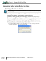
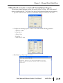
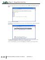
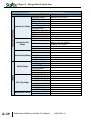
MANAGED SWITCH
QUICK START
CHAPTER
2
In This Chapter...
Connecting to the Switch for the first time . . . . . . . . . . . . . . . . . . . . . . . . . . . . . .2–2
Connecting to the switch over Ethernet: . . . . . . . . . . . . . . . . . . . . . . . . . . . . . . . . .2–2
Setting up PC for USB connection to switch: . . . . . . . . . . . . . . . . . . . . . . . . . . . . .2–7
PC to switch using Serial Port: . . . . . . . . . . . . . . . . . . . . . . . . . . . . . . . . . . . . . . . . .2–8
USB and Serial connection to switch with Terminal Software Program: . . . . . . . . . .2–9
Default Setup . . . . . . . . . . . . . . . . . . . . . . . . . . . . . . . . . . . . . . . . . . . . . . . . . . . . .2–13
Why might you need a Managed Switch? . . . . . . . . . . . . . . . . . . . . . . . . . . . . . . .2–16
Enhanced traffic filtering: . . . . . . . . . . . . . . . . . . . . . . . . . . . . . . . . . . . . . . . . . . . .2–16
Troubleshooting: . . . . . . . . . . . . . . . . . . . . . . . . . . . . . . . . . . . . . . . . . . . . . . . . . .2–16
Redundancy: . . . . . . . . . . . . . . . . . . . . . . . . . . . . . . . . . . . . . . . . . . . . . . . . . . . . .2–16
Security: . . . . . . . . . . . . . . . . . . . . . . . . . . . . . . . . . . . . . . . . . . . . . . . . . . . . . . . .2–17
Better Network ‘Awareness’: . . . . . . . . . . . . . . . . . . . . . . . . . . . . . . . . . . . . . . . . .2–18
Chapter 2 - Managed Switch Quick Start
Connecting to the Switch for the first time
Connecting to the switch over Ethernet:
NOTE: See Setting up PC for USB connection to Switch later in this chapter for the option of using USB
for switch connection.
Connecting to the switch for the first time over Ethernet requires no extra tools or driver
installation and is, therefore, the recommended way to accomplish this.
The default IP address and subnet mask of the switch is 192.168.0.1 and 255.255.255.0.
This means that your PC’s network interface card (NIC) that is connected to the switch must
be set to a compatible IP address and subnet mask to access the web-based switch
configuration tool. It is recommended that you connect your PC directly to the switch for
the initial setup of the network settings. An example IP address and subnet mask to set your
PC’s network interface to is 192.168.0.100 and 255.255.255.0.
1. Go to the Start Button and click on “Run” (if you do not see a “Run” option, type Run in the
search box and hit Enter). Type in ncpa.cpl and hit OK.
2–2
Stride Industrial Ethernet Switches User Manual
2nd Ed. Rev. A
Chapter 2 - Managed Switch Quick Start
2. Right click on the Network Interface that is connected to your switch and choose Properties.
3. Scroll down and highlight the “Internet Protocol Version 4 (TCP/IPv4)” selection and click on the
Properties button.
4. Write down the current settings so that you may put them back in after configuring the Network
settings of the switch to a compatible setup for your environment.
Stride Industrial Ethernet Switches User Manual
2nd Ed. Rev. A
2–3
Chapter 2 - Managed Switch Quick Start
5. Type in the IP address and subnet mask of 192.168.0.100 and 255.255.255.0 or another
compatible IP address and subnet mask. Click on the OK button. Click on the OK button for
the Network Interface Properties window and close the Network Connections window.
NOTE: Neither the Network Address nor the Broadcast Address for you subnet are valid host addresses.
For our example that has a Subnet Mask or 255.255.255.0 and the first three octets are 192.168.0,
neither the pc nor the switch are permitted to be assigned 192.168.0.0 or 192.168.0.255 as an IP
address.
6. Open up your web browser program such as Internet Explorer, Mozilla Firefox or other and type in
192.168.0.1 in the URL line.
7. Enter in admin for the User name and admin for the password and click on OK.
2–4
Stride Industrial Ethernet Switches User Manual
2nd Ed. Rev. A
Chapter 2 - Managed Switch Quick Start
8. Read the Software License Agreement and click the “I Accept the License” button.
Stride Industrial Ethernet Switches User Manual
2nd Ed. Rev. A
2–5
Chapter 2 - Managed Switch Quick Start
9. Click on the “Quick Setup” link on the upper left hand side of the window to access the Network
Settings.
10. Enter in the desired IP address and subnet mask that is compatible with the network that the
switch will go on or enable DHCP if that is the method you choose to assign the network
settings. Click on the “Commit Changes” button to enable the new settings.
NOTE: Neither the Network Address nor the Broadcast Address for you subnet are valid host addresses.
For our example that has a Subnet Mask or 255.255.255.0 and the first three octets are 192.168.0, neither
the pc nor the switch are permitted to be assigned 192.168.0.0 or 192.168.0.255 as an IP address.
2–6
Stride Industrial Ethernet Switches User Manual
2nd Ed. Rev. A
Chapter 2 - Managed Switch Quick Start
11. Return to steps 1 – 4 to put in the original network settings for your PC.
12. Connect your PC and the switch to the network and enter in the new IP address into your web
browser URL to access the switch. If you chose DHCP as the method for assigning the network
settings to your switch, you will need to contact the network administrator to see which IP
address has been assigned to the switch or connect via USB or serial (explained further down in
this document) to ascertain what the IP address is on the switch.
13. Now that you can access the switch, you may begin to configure the switch with the settings
appropriate for your network. If you are unsure of where to start with the configuration, go the
section titled, “Why do you need a managed switch?” to understand more about the Stride
managed switch, its capabilities and how these features can be used. Note that the default settings
enable RSTP and IGMP which will be adequate for many networks with no further
configuration.
Setting up PC for USB connection to switch:
This method can be used to initially configure the switch settings. It may also be needed if
the switch has been previously configured and the network settings are unknown. If the
switch has been set to DHCP, this method can be used to ascertain the current IP address that
has been assigned to the switch by the DHCP server.
Three things will be required in order to connect to the switch via the USB port:
1. USB driver: This can be obtained from www.automationdirect.com. Download the executable and
run it to install the driver.
2. Cable: The cable required is a Male-A connector (plugs into PC) to Male Mini B-type (5 pin)
connector (plugs into switch).
3. Terminal software tool: Hyperterminal used to come pre-installed in Windows until Windows
Vista and 7 were released. TeraTerm is another tool that can be downloaded and installed for free.
After the USB driver EXE file has been downloaded and run, plug the USB cable into the PC
and switch.
Windows will install the driver. If the New Hardware Wizard appears, select the “No, not
this time” selection and click Next. On the following screen, select the “Install Software
automatically” option and click Next. Once the driver is loaded, you may get prompted by a
window that says the driver has not been verified by Windows. Click on the “Continue
Anyway” button to complete the installation.
Stride Industrial Ethernet Switches User Manual
2nd Ed. Rev. A
2–7
Chapter 2 - Managed Switch Quick Start
To locate which COM Port has been assigned to the switch, click on “Start” menu in the PC
taskbar and choose “Control Panel”. Double click on the “System” icon. Select the
“Hardware” tab.
Click on the “Device Manager” button and then expand the “Ports (COM & LPT)” option
on the left hand side and you should see a “USB Serial Device” with a COMxx beside it.
This will be the COM port number that you will select with your Terminal software tool.
PC to switch using Serial Port:
Serial Configuration Cable
Switch RJ-45
Serial Port
1 = do not use
2 = do not use
3 = do not use
4 = Signal GND
5 = RXD
6 = TXD
7 = do not use
8 = do not use
RJ45 8-pin
Phone Plug
(8P8C)
9-pin
D-sub
(female)
Wiring Diagram
TXD
6
2
RXD
RXD
5
3
TXD
GND
4
5
shield
PC Serial Port
1
1
9
1 = do not use
2 = RXD
3 = TXD
4 = do not use
5 = Signal GND
6 = do not use
7 = do not use
8 = do not use
9 = do not use
Note: Use the above wiring diagram to make your own cable. We recommend using 22 AWG shielded cable.
In addition to the USB console port, the switches have an RJ45 console port. The RJ45
console port can connect to a -pin serial port on your PC. A driver does not need to be
installed.
2–8
Stride Industrial Ethernet Switches User Manual
2nd Ed. Rev. A
Chapter 2 - Managed Switch Quick Start
USB and Serial connection to switch with Terminal Software Program:
The software terminal program used for this tutorial will be TeraTerm. Any serial terminal
software should work fine. TeraTerm is free and can be downloaded from www.teraterm.org.
1. Open the TeraTerm software and choose Serial and the COM port connected to the switch.
2. Configure the terminal program to connect to the switch with the following parameters:
a. Baud rate: 9600
b. Data bits: 8
c. Parity: None
d. Stop bits: 1
e. Flow control: None
3. Press Enter to get the prompt shown below.
Stride Industrial Ethernet Switches User Manual
2nd Ed. Rev. A
2–9
Chapter 2 - Managed Switch Quick Start
4. Enter the login, then the password. The default user name is admin and the default password is
admin.
5. Choose selection 4 for vt100.
6. Highlight (by using the up and down arrow keys on the PC keyboard) the “Quick Setup” option
and press Enter.
7. To enable DHCP, highlight the DHCP option and press Enter. Arrow down and choose the
Enable option and press Enter. Press the c key to commit the change.
8. To set a static IP address, arrow down and highlight the “IP address” option and press Enter.
2–10
Stride Industrial Ethernet Switches User Manual
2nd Ed. Rev. A
Chapter 2 - Managed Switch Quick Start
9. Enter in the desired IP address and subnet mask. Note that the subnet mask is configured using,
what is called CIDR notation. The “/xx” number denotes how many 1’s are in the subnet mask
starting from the most significant bit. A /24 indicates a subnet mask of 255.255.255.0. A /16
indicates a subnet mask of 255.255.0.0 and a /8 indicates a subnet mask of 255.0.0.0. Once the
IP address and subnet mask have been configured, press Enter. Press the c key to commit this
change and to activate the new IP address for the switch.
10. If the switch has been configured to obtain an IP address from a DHCP server, you can also view
the IP address that is currently assigned to the switch by hitting ESC to go back to the main
menu. Arrow down and highlight the “Monitoring” option and press Enter.
Stride Industrial Ethernet Switches User Manual
2nd Ed. Rev. A
2–11
Chapter 2 - Managed Switch Quick Start
11. Highlight the first option called, “System Information” and press Enter.
12. The IP address currently assigned to the switch will be shown here.
You are now able to use your web browser with the new IP address to configure the switch.
2–12
Stride Industrial Ethernet Switches User Manual
2nd Ed. Rev. A
Chapter 2 - Managed Switch Quick Start
Default Setup
The table below shows the Default settings for the switch:
Stride Managed Switch Default Settings
Configuration Parameter
Default Setting
Main Settings
DHCP
IP Address
Subnet Mask
Default Gateway
Primary DNS Server
Secondary DNS Server
System Settings
Domain
Redundancy Protocol
System Name
Switch Location
Contact
SNMP Access
Terminal Access
Web Access
SNMP Firmware Loading
Remote Access Security Command Line Access
Automatic Logout
SNMP Read-Only
SNMP Read/Write
Terminal and Web
Name
Admin
Negotiation
Port Settings
Speed/Duplex
Set IP per Port
Switch Time Settings
Manage Firmware
Install Firmware
Disabled
192.168.0.1
255.255.255.0
none
none
none
Rapid Spanning Tree Protocol
Switch model (i.e. SE-SW8MG-4P)
<Set Location of Switch>
<Set Name (and email) of contact for Switch>
Basic and secure SNMP access
SSH and telnet access
Basic and secute SNMP access
Disabled
Enabled
Disabled
Name: public No Password
Name: private No Password
Name: admin Password: admin
port x (x being port number)
Enabled
Auto
For non Gigabit Switches: 10h,10f,100h,100f all on
For Gigabit Switches: 10h,10f,100h,100f,1000f all on
Off
Flow Control
1000f selected
SFP
Provide/Do Not Provide IP Do not provide IP address to any device
Off for all ports
Enabled
blank for all ports
Address
none
NTP Server
Not set
Timezone
1970-01-01
Set Switch Date
current time
Set Switch Time
Top line selected
Default
HTTP
Protocol
blank
All Other Fields
Stride Industrial Ethernet Switches User Manual
2nd Ed. Rev. A
2–13
Chapter 2 - Managed Switch Quick Start
Stride Managed Switch Default Settings (cont’d)
Configuration Parameter
Default Setting
Redundancy Settings
Settings
2–14
Rapid Spanning Tree Protocol
Redundancy Protocol
32768
Bridge Priority
20
Maximum Age
2
Hello Time
15
Forward Delay
Spanning Tree Settings
6
Transmission Limit
Region Name
0 (grayed out)
Configiguration Revision
20 (grayed out)
Max Hops
None by default
MST Instance
Off for all ports
Exclude
128 for all ports
Priority
Spanning Tree Port Path Cost
20000 for all 10 / 100 / 1000 Ports,
200,000 for all 10 / 100 ports
Settings
Auto for all ports
Type
Auto for all ports
Point-to-Point
Off for all ports
Enable
Ring x (x being port number) Grayed out by default
Ring Name
none
Real-time Ring Settings Primary Port
none
Backup Port
Automatic Master
Ring Master
Send all high priority fames before any others
Priority Frame Setting
On for all ports
Use 802.1p Tag Priority
On for all ports
Use IP ToS/DiffServ
QoS/CoS Settings
Tag for all ports
Priority Precedence
Normal for all ports
Default Out Q
Transparent for all ports
Type
Normal
Priority 0 (Best Effort)
Background
Priority 1 (Background)
Background
Priority 2 (Spare)
Normal
Priority 3 (Excellent Effort)
802.1p Tag Settings
Priority 4 (Controlled Load) Expedited
Expedited
Priority 5 (Video)
Urgent
Priority 6 (Voice)
Priority 7 (Network Control) Urgent
Limit Broadcast and Multicast Disabled for all ports
Message Rate Limiting
Enabled for all ports
Forward Unknown
Stride Industrial Ethernet Switches User Manual
2nd Ed. Rev. A
Chapter 2 - Managed Switch Quick Start
Stride Managed Switch Default Settings (cont’d)
Configuration Parameter
Default Setting
Multicast Filtering
(IGMP)
Protocol Settings
Port Settings
Virtual LANs
(VLANs)
VLAN Settings
IGMP Mode
Multicast Suppression
IGMP Version
Robustness
Query Interval
Query Response Interval
Exclude
Router
VLAN Mode
Core Type
Learning
Default VLAN Settings
Security Settings
PVID
Force
Type
Same settings as in Main
Remote Access Security Settings
Global Security Enable
Port Security Enables
Port Enabled
Port Security MAC Entries Entry
Ipsec Settings
Disabled by default
IKE Phase 1 Policies
VLAN Port Settings
IKE Phase 2 Policies
IKE Policy
IKE Phase 2 Algorithms
Alarm (OK) Output
Monitoring Settings
Modbus
SNMP Notifications
A power input lost enabled
All others disabled
Enabled
Station Number
Transport Layers
TCP Timeout
TCP Connection Limit
Port
Everything disabled by
default
Active IGMP handling
All unreserved multicast
Version 2
2
125
10
Disabled for all ports
Auto detect for all ports
Disabled
0x8100
Shared
Management: Tag-Based, ID=1, FID=0, CPU selected
as well as all ports
1
Off for all ports
Transparent for all ports
Off
Off for all ports
None
None
1 by default but Disabled with 8h lifetime
(anonymous source and dest)
Cipher aes (AES Rijndael) Enabled
Cipher 3DES Enabled
Hash hmac_SHA1 Enabled
Hash hmac_SHA256 Enabled
Compression deflate Enabled
All others disabled
Disabled
1
TCP & UDP
0
4
502
Stride Industrial Ethernet Switches User Manual
2nd Ed. Rev. A
2–15
Chapter 2 - Managed Switch Quick Start
Why might you need a Managed Switch?
Enhanced traffic filtering:
An unmanaged switch will filter out many packets from an end device that a hub would not
but there are still many types of packets that an unmanaged switch cannot determine what to
do with and must forward on to all ports. Whenever a device receives a packet that is not
specifically targeted to that device, there is a certain amount of processing time that takes
away from other important tasks that the device may really need to be spending time on.
These ‘unintentional’ packets also get in the way of the packets that are intended for that
device. This hurts the determinism of a process. A managed switch can help with this in
several different ways:
• Multicast Filtering (IGMP): It is common in a control system to see a large amount of Multicast
packets. These packets cannot be filtered out by an unmanaged switch. The Stride managed switch
can intelligently ‘learn’ whether certain Multicast packets should be sent to the devices on its ports
and will filter them or not filter them appropriately.
• VLANs: A VLAN is a logical way to separate networks in ways that used to require physical
separation. Because of existing network infrastructure or for ease of wiring (and reduced cost), it
may be difficult to physically separate networks that need separation due to the type of packets that
are on them. Setting up VLANs can simplify the setup for these situations.
• Traffic Priority (QoS/CoS): Some traffic may be more important to a specific device than other
traffic. Using the Quality of Service feature, the Stride switch can apply tags to a packet coming
into the switch to give that packet a higher priority going to another switch. The last switch will
then remove the tag before sending the packet to the device. It can also use the tags applied to the
packets by the devices themselves if they support this.
Troubleshooting:
As Ethernet messaging becomes more of the standard for communications between devices in
a control system, it may become more necessary to gain visibility to these types of
communications. With hubs, it was possible to see the messages between devices because
hubs broadcast every packet to all ports. Unmanaged switches took away this capability as
they filter unicast packets to only the intended physical ports. Managed switches can help
with this by utilizing the Port Mirroring feature. The Stride managed switch can also give
you visibility in to the type of packets that are being sent across the switch by viewing the
Network Statistics page in the configuration.
• Port Mirroring: With the Port Mirroring feature you simply specify which ports’ data you want to
view and where to send that data. Plug your PC into that port and use Ethernet sniffing software
(such as Wireshark) and you can now see the data being sent back and forth.
• Network Statistics: By looking at what kind of packets that are coming in and out of the switch,
you can determine what action needs to be taken to make your network work better. If you see a
lot of Multicast traffic, utilize the Multicast Filtering feature. If there are lots of broken packets,
troubleshoot the wiring to determine where the problem lies.
Redundancy:
The downside of any Ethernet switch is the simple fact that it is another electronic
component in the system that could be subject to failure. There is also the risk that as a
network grows and more switches are added to it, a ‘ring’ may accidentally be created causing
2–16
Stride Industrial Ethernet Switches User Manual
2nd Ed. Rev. A
Chapter 2 - Managed Switch Quick Start
the network to go down. Utilizing the Spanning Tree and/or Real-Time Ring feature of the
Stride managed switch can reduce these risks.
• STP: The Spanning Tree protocol simply allows you to purposely create a ring that allows for
multiple, redundant paths on the network but intelligently decides one path when the network
comes up and assigns alternate paths if some part of the original path goes down.
• RSTP: The Rapid Spanning Tree Protocol is the preferred method in the industry today as the
manner in which it decides the original paths and the time in which it changes over to alternate
paths is much, much faster than the original Spanning Tree Protocol. It is really only useful to
enable the older STP if your legacy network requires this protocol. The RSTP feature is enabled by
default.
• Real-Time Ring: In many Control Systems, the time it takes for the RSTP algorithm to change
paths upon some network event is too slow. The Real-Time Ring is proprietary to the Stride
managed switches but it has the advantage of changing paths very, very quickly.
Security:
Network security has become a great concern for facilities these days. And while the network
devices themselves are only one part of a network security strategy, the Stride managed
switches have several security features:
• Port Control: In the “Port Settings” setup, you can disable ports that are not being used. This can
limit unauthorized access.
• Security Settings: There are several different methods of enabling security in the switch. There are
security methods to prevent access to the switch (Remote Access Security), you can determine
which devices can connect to the switch (Port Security MAC Entries) and you can enable
encryption for data going between switches (IPsec).
• Remote Access Security: You can disable access to the switch or implement secure pass-wording in
order to access the switch.
• IPsec: There are many different methods that can be employed to encrypt the data going to or
from the switch. The particular method (encryption protocol/algorithm) will most likely be
determined by your network administrator.
Stride Industrial Ethernet Switches User Manual
2nd Ed. Rev. A
2–17
Chapter 2 - Managed Switch Quick Start
Better Network ‘Awareness’:
The ability of the process to know when something is wrong with the network and what is
wrong with the network is a great feature of the Stride managed switches. Your PLC or
controlling device can make ‘smarter’ decisions as to what alarms or fallback behavior to
trigger based upon the different diagnostic data that is supplied by the switch.
• Modbus Stats: If you have a controlling device on the network that has Modbus TCP or UDP
client capability, there are several diagnostic tags that can be read from the switch to indicate the
health of the network.
• SNMP: SNMP stands for Simple Network Management Protocol and is used for just that. There
are many software tools out there that can query or receive ‘traps’ sent by the Stride managed switch
to ascertain events or health of the switch.
• Port and Power Status (Alarm Output): The Stride managed switch has two power inputs that can
be used for redundancy. If one of the power inputs fails, there is a relay contact that can be
configured to report this failure.
• Spanning Tree Status: The switch can be configured to report when something in the Spanning
Tree has changed.
• Real-Time Ring Status: The Real-Time Ring status can be ascertained from other devices as well.
• MAC Table: The switch keeps a table of the MAC IDs of devices that are communicating on it
2–18
Stride Industrial Ethernet Switches User Manual
2nd Ed. Rev. A