1
APPLICATION NOTE
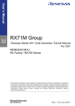
RX64M Group
RX Driver Package User’s Manual
R01AN2460EJ0101
Rev.1.01
Jan 5, 2015
Introduction
This document is the RX64M Group RX Driver Package User’s Manual, version 1.01.
This User’s Manual describes basic structures, features and usage of RX Driver Package applications, and about the
sample application program using the FIT modules included in this package.
Target Device
RX64M Group (Renesas Starter Kit+ RX64M)
When using this application note with your product, careful evaluation is recommended.
And when using this application note with other Renesas MCUs, careful evaluation is recommended after making
modifications to comply with the alternate MCU.
Related Documents
RX Family Board Support Package Module Using Firmware Integration Technology (R01AN1685EU)
Firmware Integration Technology User’s Manual (R01AN1833EU)
RX Family Adding Firmware Integration Technology Modules to Projects (R01AN1723EU)
RX Family Adding Firmware Integration Technology Modules to CS+ Projects (R01AN1826EJ)
The User’s Manual provided with the RX Driver Package Application.
R01AN2460EJ0101 Rev.1.01
Jan 5, 2015
Page 1 of 29
RX64M Group
RX Driver Package User’s Manual
Contents
1. Overview ........................................................................................................................................... 3
1.1 Applicability ....................................................................................................................................... 3
1.2 Operating Environment ..................................................................................................................... 3
2. About RX Driver Package ................................................................................................................. 4
2.1 System Structure ............................................................................................................................... 4
2.2 RX Driver Package Features ............................................................................................................ 5
3.
3.1
3.2
3.3
Structure of the RX64M Group RX Driver Package .......................................................................... 6
Folder Structure ................................................................................................................................. 6
Module Structure ............................................................................................................................... 7
FIT Modules ...................................................................................................................................... 7
4. Usage Procedures ............................................................................................................................. 9
4.1 Environment Used ............................................................................................................................. 9
4.2 Install RX Driver Package in e2 studio .............................................................................................. 9
4.3 Application Creation ........................................................................................................................ 10
4.3.1 Create a Workspace and a Project ............................................................................................ 10
4.3.2 Prepare to Embed the FIT Modules ........................................................................................... 16
4.3.3 Install the FIT Modules with the FIT Plugin. ............................................................................... 19
4.3.4 Create an LED Driving Program ................................................................................................ 23
4.3.5 Build and Try Running the Program .......................................................................................... 24
5.
5.1
5.2
5.3
5.4
RX Driver Package Application ....................................................................................................... 27
RX Driver Package Application Structure ....................................................................................... 27
RX Driver Package Application Features ........................................................................................ 27
RX Driver Package Application Usage Example (when e2 studio is used) ..................................... 28
When Using in Combination with an RX Driver Package Application ............................................. 28
6. Supplement ..................................................................................................................................... 28
6.1 M3S-T4-Tiny(TCP/IP protocol stack ) ........................................................................................ 28
Website and Support ............................................................................................................................... 29
R01AN2460EJ0101 Rev.1.01
Jan 5, 2015
Page 2 of 29
RX Driver Package User’s Manual
RX64M Group
1.
1.1
Overview
Applicability
This User’s Manual applies to the RX64M Group RX Driver Package, version 1.01.
1.2
Operating Environment
This package runs under the operating environment described below.
Table 1.2.1 Operating Environment
Microcontroller
Evaluation board
Integrated development
environment (IDE)
Cross tools
Emulator
RX64M Group
Renesas Starter Kit+ RX64M
e2 studio, V3.1.2 or later
Or:
CS+ V3.00.00 or later
RX Family C/C++ Compiler Package V2.02.00 or later
E1, E20
R01AN2460EJ0101 Rev.1.01
Jan 5, 2015
Page 3 of 29
RX Driver Package User’s Manual
RX64M Group
2.
About RX Driver Package
The RX Driver Package is a software platform (framework) that combines the following modules to be required for
development in a single package. Since the package contains multiple modules, you can start developing immediately
without having to obtain each module separately.
Board Support Package (BSP) module
FIT peripheral function modules (free version)
FIT middleware modules (free version)
FIT interface modules
You can develop the user application layer with ease by using the Sample Application Program (RX Driver Package
Application) which utilizes the RX Driver Package.
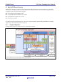
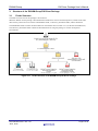
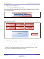
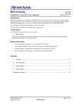
2.1
System Structure
The figure below shows the system structure of the RX Driver Package.
* Items marked with an asterisk are under development.
Figure 2.1.1 System Structure
R01AN2460EJ0101 Rev.1.01
Jan 5, 2015
Page 4 of 29
RX Driver Package User’s Manual
RX64M Group
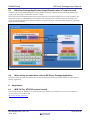
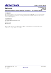
2.2
RX Driver Package Features
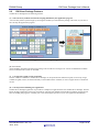
The RX Driver Package has the following features.
(a) Select necessary modules and start developing immediately the application program
You can easily build a system simply by selecting the modules you need from the package. After that, all you have to
do is develop the application program.
Figure 2.2.1 An example of system build
(b) Free to use
All the modules included in the RX Driver Package can be used free of charge. Free versions of middleware modules
such as TCP/IP and file system are included.
(c) Can upgrade to paid versions of modules
The free versions of modules in the RX Driver Package can be replaced with commercial (paid) versions. By using a
commercial (paid) version, all the functionality of the module will be available, as well as support about a commercial
version.
(d) Check operation including user application
The RX Driver Package Application is provided as a sample user application that uses the RX Driver Package. The RX
Driver Package Application consists of programs for operating each module in the RX Driver Package, and the project
files for building the programs. It enables you to start checking the operation of your user application immediately.
R01AN2460EJ0101 Rev.1.01
Jan 5, 2015
Page 5 of 29
RX64M Group
3.
3.1
RX Driver Package User’s Manual
Structure of the RX64M Group RX Driver Package
Folder Structure
The folder structure used in this package is shown below.
When the ZIP file for this package is downloaded from the Renesas web site and decompressed, a folder of the same
name will be present and it will contain a FITModules folder, a reference_documents folder, and this document.
The FITModules folder contains the FIT modules for the modules shown in table 3.3.1 (as ZIP files and XML files).
The reference_documents folder contains the documentation for using this package in various development
environments.
Figure 3.1.1 Folder Structure of the RX64M Group RX Driver Package
R01AN2460EJ0101 Rev.1.01
Jan 5, 2015
Page 6 of 29
RX Driver Package User’s Manual
RX64M Group
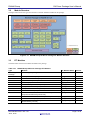
3.2
Module Structure
The figure below shows the types and structure of the FIT modules included in this package.
Figure 3.2.1 RX64M Group RX Driver Package FIT Module Structure
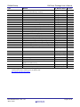
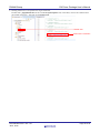
3.3
FIT Modules
The table below lists the FIT modules included in this package.
Table 3.3.1 RX64M Group RX Driver Package FIT Modules
Type
Board Support
Package
Device Driver
Device Driver
Device Driver
Device Driver
Device Driver
Device Driver
Device Driver
Device Driver
Device Driver
Device Driver
Device Driver
Device Driver
Module
Board support package
FIT Module Name
r_bsp
Version
2.70
Interrupt Controller (IRQ)
Data transfer controller (DTC)
DMA controller (DMAC)
General-purpose I/O
Multi-function pin controller (MPC)
Compare match timer (CMT)
Compare Match Timer W (CMTW)
Real-Time Clock (RTC)
Serial Communications Interface with FIFO (SCI:
Asynchronous/Clock Synchronous)
Serial Communications Interface (SCI: Simple I2C Bus)
I2C Bus Interface (RIIC)
Serial Peripheral Interface (RSPI: Device Driver for
Serial Memory Control)
r_irq_rx
r_dtc_rx
r_dmaca_rx
r_gpio_rx
r_mpc_rx
r_cmt_rx
r_cmtw_rx
r_rtc_rx
r_scif_rx
1.30
2.01
1.01
1.30
1.30
2.40
1.00
2.10
1.00
r_sci_rx64m
r_riic_rx
r_rspi_smstr_rx
1.00
1.05
1.07
R01AN2460EJ0101 Rev.1.01
Jan 5, 2015
Page 7 of 29
RX Driver Package User’s Manual
RX64M Group
Type
Device Driver
Device Driver
Device Driver
Device Driver
Device Driver
Device Driver
Device Driver
Device Driver
Device Driver
Device Driver
Device Driver
Device Driver
Device Driver
Device Driver
Device Driver
Device Driver
Device Driver
Middleware
Middleware
Middleware
Middleware
Module
Quad Serial Peripheral Interface (QSPI: Device
Driver for Serial Memory Control)
USB basic firmware
USB host communication device class
USB host human interface device class
USB host mass storage class
USB peripheral communication device class
USB peripheral mass storage class
Ethernet controller PTP controller (EPTPC)
Ethernet controller (ETHERC)
12-Bit A/D Converter (S12AD)
D/A Converter (DAC)
Flash Memory (Flash API)
Sampling rate converter (SRC)
Serial Sound Interface (SSI)
Parallel Data Capture Unit (PDC)
Byte Queue Buffer (Data Management)
Long Queue Buffer (Data Management)
M3S-S2-Tiny (ADPCM encoding/decoding library)
M3S-T4-Tiny (TCP/IP protocol stack library)
M3S-TFAT-Tiny (FAT file system)
DHCP Client Module
Middleware
Middleware
Middleware
DNS Client Module
FTP Server Module
HTTP Server Module
Interface
Interface
Interface
FIT Module Name
r_qspi_smstr_rx
Version
1.06
r_usb_basic
r_usb_hcdc
r_usb_hhid
r_usb_hmsc
r_usb_pcdc
r_usb_pmsc
r_ptp_api_rx
r_ether_rx
r_s12ad_rx64m
r_dac_rx
r_flash_rx
r_src_api_rx
r_ssi_api_rx
r_pdc_rx
r_byteq
r_longq
r_s2_rx
r_t4_rx
r_tfat_rx
r_t4_dhcp_client_r
x
r_t4_dns_client_rx
r_t4_ftp_server_rx
r_t4_http_server_r
x
r_posix
r_socket
r_t4_driver_rx64m
1.00
1.00
1.00
1.00
1.00
1.00
1.01
1.00
1.00
2.10
1.11
1.10
1.00
1.00
1.20
1.20
3.01
2.01
3.00
1.01
POSIX Wrapper
Socket API Module for M3S-T4-Tiny
Interface Conversion for Ethernet Controller Driver
Module for M3S-T4-Tiny
Interface
File driver for FTP server and Web server Module r_t4_file_driver_rx
Interface
M3S-TFAT-Tiny Memory Driver Interface Module
r_tfat_driver_rx
Note: This package includes the M3S-T4-Tiny (TCP/IP protocol stack library) of evaluation version.
commercial version, please go to the below URL.
http://www.renesas.com/mw/t4
R01AN2460EJ0101 Rev.1.01
Jan 5, 2015
1.01
1.02
1.03
1.00
1.20
1.01
1.00
1.00
For the
Page 8 of 29
RX64M Group
4.
RX Driver Package User’s Manual
Usage Procedures
The RX Driver Package allows programs to be easily constructed by using the FIT plugin included in e 2 studio. The
remainder of this section presents a simple usage example using e2 studio. To use CS+, see the document “RX Family
Adding Firmware Integration Technology Modules to CS+ Projects (R01AN1826EJ)” included in this package.
4.1
Environment Used
The RX64M is used as the target microcontroller and the Renesas Starter Kit+ RX64M is used as the target board. If a
different environment is used, replace the specifics used in the example with the ones for that environment as you read.
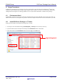
4.2
Install RX Driver Package in e2 studio
Install the FIT modules in the RX Driver Package into e2 studio.
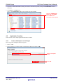
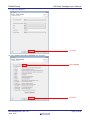
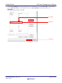
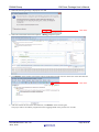
1. Decompress the downloaded file an_r01an2460ej0101_rx64m.zip into an arbitrary directory.
2. Open the folder that was decompressed and open the FITModules folder in that folder.
3. Select all the files in the FITModules folder and click Copy in the Edit menu.
Select all files and click
Copy in the Edit menu.
R01AN2460EJ0101 Rev.1.01
Jan 5, 2015
Page 9 of 29
RX64M Group
RX Driver Package User’s Manual
4. Open the e2 studio install folder (Usually, this will be c:/Renesas/e2_studio.) and open the FITModules folder in
that folder.
5. Click Paste on the Edit menu.
The e2 studio FITModules folder will be copied to the FIT modules.
Open the FITModules
folder and click Paste
on the Edit menu.
The folder will be copied.
4.3
Application Creation
In this section, create a simple application that drives an LED.
4.3.1
Create a Workspace and a Project
First, create a new workspace and a new project.
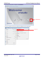
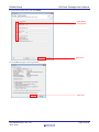
1. Start e2 studio.
2. Enter an arbitrary workspace folder in the displayed dialog box and click OK.
Enter a workspace
folder.
Click OK.
R01AN2460EJ0101 Rev.1.01
Jan 5, 2015
Page 10 of 29
RX64M Group
RX Driver Package User’s Manual
3. When the following window is displayed, click Workbench.
Click Workbench.
4. When the workbench has started, select New from the File menu and click C Project.
Click here.
R01AN2460EJ0101 Rev.1.01
Jan 5, 2015
Page 11 of 29
RX64M Group
RX Driver Package User’s Manual
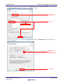
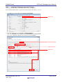
5. Enter the project name. For the project type, click Sample Project under Executable (Renesas). For the tool chain,
click Renesas RXC Toolchain. After making these settings, click Next.
Enter the
project name.
Click here.
6. Select the target. Click the “...” button under Target Selection and select R5F564MLCxFC. After making these
settings, click Next.
Click here and
select
R5F564MLCxFC.
Click here.
R01AN2460EJ0101 Rev.1.01
Jan 5, 2015
Page 12 of 29
RX64M Group
RX Driver Package User’s Manual
7. Simply click Next here.
Click here.
8. Simply click Next here.
Click here.
R01AN2460EJ0101 Rev.1.01
Jan 5, 2015
Page 13 of 29
RX64M Group
RX Driver Package User’s Manual
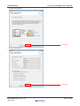
9. Simply click Next here.
Click here.
10. Select C(C99) under Library Structure and click Next.
Select C(C99).
Click here.
R01AN2460EJ0101 Rev.1.01
Jan 5, 2015
Page 14 of 29
RX64M Group
RX Driver Package User’s Manual
11. Clear all four check boxes and click Finish.
Clear all the
check boxes.
Click here.
12. Click OK. The project will be generated.
Click here.
R01AN2460EJ0101 Rev.1.01
Jan 5, 2015
Page 15 of 29
RX64M Group
4.3.2
RX Driver Package User’s Manual
Prepare to Embed the FIT Modules
Since the FIT modules are independently initialized in BSP, it is necessary to modify certain aspects of the project
generated by e2 studio.
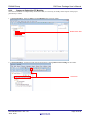
1. In Project Explorer, delete the dbsct.c and typedefine.h files in the src folder.
Delete these files.
2. In Project Explorer, click Project and open the properties by clicking Renesas Tool Settings in the toolbar.
Click here.
R01AN2460EJ0101 Rev.1.01
Jan 5, 2015
Page 16 of 29
RX64M Group
RX Driver Package User’s Manual
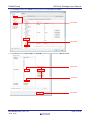
3. Click Settings under C/C++ Build in the properties and click Section under Linker.
Click here.
Click here.
4. In Section View, delete PResetPRG and PIntPRG. Click each section and click Delete Section.
Click here.
Click here.
Click here.
R01AN2460EJ0101 Rev.1.01
Jan 5, 2015
Page 17 of 29
RX64M Group
RX Driver Package User’s Manual
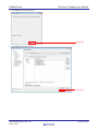
5. Add an OPT_MEMORY section after the R section. Click the R section and click Add Section. Click the added
section, NEW_SECTION_1, and modify the name to be OPT_MEMORY, and input the address to be
0x00120064.
After completing the addition, click OK.
Click here.
Add here.
Click here.
R01AN2460EJ0101 Rev.1.01
Jan 5, 2015
Page 18 of 29
RX64M Group
4.3.3
RX Driver Package User’s Manual
Install the FIT Modules with the FIT Plugin.
Install the required modules with the FIT plugin into the created project.
Here, install the BSP module (r_bsp) and the compare match timer driver (r_cmt_rx).
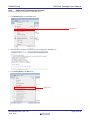
1. In the File menu, select New and click Renesas FIT Module.
Click here.
2. Select the created project with Project to Add FIT Module to.
Next, select RX64M under Group and select RSKRX64M from Target Board.
Next, click r_bsp and r_cmt_rx in the module list and click Finish.
Select the project.
Select this item.
Click here.
R01AN2460EJ0101 Rev.1.01
Jan 5, 2015
Page 19 of 29
RX64M Group
RX Driver Package User’s Manual
3. Click OK with changing anything.
Click here.
4. Click OK with changing anything.
Click here.
R01AN2460EJ0101 Rev.1.01
Jan 5, 2015
Page 20 of 29
RX64M Group
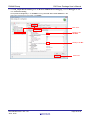
RX Driver Package User’s Manual
5. Open r_bsp/board/rskrx64m from the e2 studio Project Explorer, select the two files r_bsp_config_reference.h
and r_bsp_interrupt_config_reference.h, and click Copy on the Edit menu.
Select these two files
and click Copy on
the Edit menu.
6. Select r_config from the e2 studio Project Explorer and click Paste on the Edit menu.
Select the r_config
folder and click Paste
on the Edit menu.
7. Change the names of the two copied files to r_bsp_config.h and r_bsp_interrupt_config.h. That is, delete the
“_reference_” part of the file names.
Rename these files.
R01AN2460EJ0101 Rev.1.01
Jan 5, 2015
Page 21 of 29
RX64M Group
RX Driver Package User’s Manual
8. Modify platform.h to correspond to the target board used.
Double click r_bsp/platform.h from the e2 studio Project Explorer and, in the editor, remove the comment from
the include line for the r_bsp.h file for the RSKRX64M.
Double click.
Remove the comment.
R01AN2460EJ0101 Rev.1.01
Jan 5, 2015
Page 22 of 29
RX64M Group
4.3.4
RX Driver Package User’s Manual
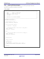
Create an LED Driving Program
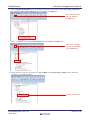
Create a program that toggles the LED0 on/off state every 0.5 seconds using the compare match timer.
Open the file src/led_sample.c and modify it as shown below.
src/led_sample.c
/***********************************************************************/
/*
*/
/* FILE
:Main.c or Main.cpp
*/
/* DATE
:Tue, Oct 31, 2006
*/
/* DESCRIPTION :Main Program
*/
/* CPU TYPE
:
*/
/*
*/
/* NOTE:THIS IS A TYPICAL EXAMPLE.
*/
/*
*/
/***********************************************************************/
#include "platform.h"
#include "r_cmt_rx_if.h"
/* LED Currently status */
uint32_t ledstatus = LED_OFF;
void call_back(void *pdata)
{
if (ledstatus == LED_OFF)
{
/* Turn ON the LED0 If the status is LED_OFF */
LED0 = LED_ON;
ledstatus = LED_ON;
}
else
{
/* Turn OFF the LED0 If the status is LED_ON */
LED0 = LED_OFF;
ledstatus = LED_OFF;
}
}
void main(void)
{
uint32_t cmt_ch;
/* LED0 off */
LED0 =LED_OFF;
/* Create of 0.5 second(2Hz) cyclic timer. */
R_CMT_CreatePeriodic(2, &call_back, &cmt_ch);
while(1);
}
R01AN2460EJ0101 Rev.1.01
Jan 5, 2015
Page 23 of 29
RX Driver Package User’s Manual
RX64M Group
4.3.5
Build and Try Running the Program
Build the program just created and verify that it runs.
1. Click Build Project on the Project menu.
Click here.
2. When the build completes, the following will be displayed in Console view.
3. Click Debug Build on the Run menu.
Click here.
R01AN2460EJ0101 Rev.1.01
Jan 5, 2015
Page 24 of 29
RX64M Group
RX Driver Package User’s Manual
4. Click led_sample HardwareDebug under the Renesas GDB Hardware Debugging. Click the Debugger tab and
click Connection Setting.
Modify EXTAL Frequency to be 24.0000 and change Provide Power from Emulator to No.
When these changes have been made, click Debug.
Click here.
Modify to be
24.0000.
Modify to be No.
Click here.
R01AN2460EJ0101 Rev.1.01
Jan 5, 2015
Page 25 of 29
RX64M Group
RX Driver Package User’s Manual
5. When the following message is displayed, click Yes.
Click here.
6. When the load module download completes, a Debug perspective opens.
7. Click Restart on the toolbar. The program will be executed and a break will occur at the start of the main function.
Click here.
8. After the break at the start of the main function, click Restart on the tool bar again.
The project will be run and the program will iterate toggling LED0 with a period of 0.5 seconds.
R01AN2460EJ0101 Rev.1.01
Jan 5, 2015
Page 26 of 29
RX Driver Package User’s Manual
RX64M Group
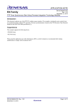
5.
5.1
RX Driver Package Application
RX Driver Package Application Structure
The RX Driver Package Application is a sample application program provided so that users can use the RX Driver
Package easily. The RX Driver Package Application consists of an application program that operates using device
drivers and middleware included in the RX Driver Package and a project file for building that application. This allows
users to start evaluation quickly.
Sample application program
Project file
Figure 5.1.1 RX Driver Package Application Structure
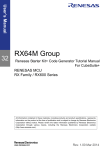
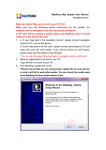
Renesas plans to release a variety of types of this RX Driver Package Application in the future, such as system
programs that operate using a combination of multiple drivers and middleware and evaluation programs for independent
modules from the RX Driver Package.
Network server
and cliant
Camera control program
Audio player (ADPCM)
Device driver evaluation
program
Boot loader
Image and video
middleware control
program
Boot loader
RX Driver Package
Application
Figure 5.1.2 Types of RX Driver Package Application
5.2
RX Driver Package Application Features
The RX Driver Package Application has the following features.
The RX Driver Package Application is evaluated in combination with the RX Driver Package.
Project files are included in the RX Driver Package Application. Since both build and debug configurations for the
application project are already set up in the provided project file, the user can quickly begin building and evaluating
simply by importing the project into a workspace.
If e2 studio is used as the integrated development environment (IDE), the device drivers and middleware used in the
application project can be automatically added to the project by using the FIT plugin provided with e2 studio.
Renesas provides the RX Driver Package Application without charge.
R01AN2460EJ0101 Rev.1.01
Jan 5, 2015
Page 27 of 29
RX Driver Package User’s Manual
RX64M Group
5.3
RX Driver Package Application Usage Example (when e2 studio is used)
The device drivers and middleware required by the RX Driver Package Application are automatically added to the
project by the FIT plugin, which comes with the e2 studio.
After the project provided with the RX Driver Package Application has been installed in an e2 studio workspace, the
required device drivers and middleware from the RX Driver Package are also installed simply by installing in the
project by selecting the RX Driver Package Application with the FIT plugin. Therefore all that remains is to build the
project and start evaluation.
FIT plugin
Project installation
HTTP (Web server)
Application program
Project file
Project
Application installation
HTTP (Web server)
Application program
The required device drivers
and middleware from the
RX Driver Package are
installed automatically.
Figure 5.3.1 FIT Plugin Automatic Installation
5.4
When Using in Combination with an RX Driver Package Application
See the document provided with each RX Driver Package Application for detailed usage methods for that RX Driver
Package Application.
6.
6.1
Supplement
M3S-T4-Tiny(TCP/IP protocol stack )
This package include the M3S-T4-Tiny (TCP/IP protocol stack library) of evaluation version. For the commercial
version, please go to the below URL.
http://www.renesas.com/mw/t4
R01AN2460EJ0101 Rev.1.01
Jan 5, 2015
Page 28 of 29
RX64M Group
RX Driver Package User’s Manual
Website and Support
Renesas Electronics Website
http://www.renesas.com/
Inquiries
http://www.renesas.com/contact/
All trademarks and registered trademarks are the property of their respective owners.
R01AN2460EJ0101 Rev.1.01
Jan 5, 2015
Page 29 of 29
Revision History
Rev.
1.00
1.01
Date
Sep 1, 2014
Jan 5, 2015
Description
Page
Summary
First edition issued
Updated existing modules to latest modules.
Added new release modules to the package.
A-1
General Precautions in the Handling of MPU/MCU Products
The following usage notes are applicable to all MPU/MCU products from Renesas. For detailed usage notes on the
products covered by this document, refer to the relevant sections of the document as well as any technical updates that
have been issued for the products.
1. Handling of Unused Pins
Handle unused pins in accord with the directions given under Handling of Unused Pins in the manual.
The input pins of CMOS products are generally in the high-impedance state. In operation with an unused pin
in the open-circuit state, extra electromagnetic noise is induced in the vicinity of LSI, an associated shootthrough current flows internally, and malfunctions occur due to the false recognition of the pin state as an
input signal become possible. Unused pins should be handled as described under Handling of Unused Pins in
the manual.
2. Processing at Power-on
The state of the product is undefined at the moment when power is supplied.
The states of internal circuits in the LSI are indeterminate and the states of register settings and pins are
undefined at the moment when power is supplied.
In a finished product where the reset signal is applied to the external reset pin, the states of pins
are not guaranteed from the moment when power is supplied until the reset process is completed.
In a similar way, the states of pins in a product that is reset by an on-chip power-on reset function
are not guaranteed from the moment when power is supplied until the power reaches the level at
which resetting has been specified.
3. Prohibition of Access to Reserved Addresses
Access to reserved addresses is prohibited.
The reserved addresses are provided for the possible future expansion of functions. Do not access these
addresses; the correct operation of LSI is not guaranteed if they are accessed.
4. Clock Signals
After applying a reset, only release the reset line after the operating clock signal has become stable.
When switching the clock signal during program execution, wait until the target clock signal has
stabilized.
When the clock signal is generated with an external resonator (or from an external oscillator) during a reset,
ensure that the reset line is only released after full stabilization of the clock signal. Moreover, when
switching to a clock signal produced with an external resonator (or by an external oscillator) while program
execution is in progress, wait until the target clock signal is stable.
5. Differences between Products
Before changing from one product to another, i.e. to a product with a different type number, confirm
that the change will not lead to problems.
The characteristics of an MPU or MCU in the same group but having a different part number may differ in
terms of the internal memory capacity, layout pattern, and other factors, which can affect the ranges of
electrical characteristics, such as characteristic values, operating margins, immunity to noise, and amount of
radiated noise. When changing to a product with a different part number, implement a system-evaluation test
for the given product.