1
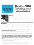
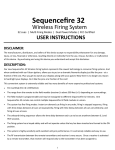
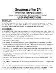
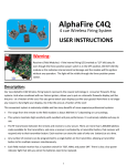
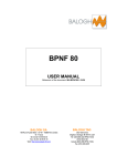
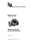
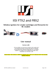
MS12Q 12 Cue Wireless Firing System 12 cues | Dual Power Modes | FCC Certified USER INSTRUCTIONS Warning: FIRE LED’s If a FIRE LED (labeled left) stays lit when the unit is powered on, no matter which position the rocker switch is in, and at the same time the corresponding TEST LED is always off, the channel has been shorted and permanently damaged. IF THIS OCCURS DO NOT USE THIS CHANNEL as the channel will fire an igniter without any TEST LED’s DIGITAL DISPLAY operation by the user. Discontinue use of the shorted-out channel until the system can be repaired or replaced. Additionally, if the DIGITAL DISPLAY (labeled above) turns off, and at the same time the FIRE LEDs and TEST LEDs are turned on, while the rocker switch is in the TEST or ARM position, then immediately turn off the firing system and remove or disconnect the batteries. IF THIS OCCURS DO NOT USE THE SYSTEM as it will fire igniters without any operation by the user. Discontinue use of the system until it can be repaired or replaced. DISCLAIMER: The manufacturers, distributors, and sellers of this device accept no responsibility whatsoever for any damage, injury, or loss, financial or otherwise, resulting directly or indirectly from the use, misuse, function, or malfunction of this device. By purchasing and using this device you understand and accept this disclaimer. 1 Description: The MS12Q Wireless Firing System is FCC Certified, and represents the newest technology in consumer firing systems. And when combined with our Falcon igniters, you can put on a dramatic fireworks display just like the pros - at a fraction of the cost. Plus you get to watch your displays along with your guests! Now there is no longer any reason to hand light your displays. Do it like the pros at a fraction of the cost! This convenient system is extremely reliable and has many benefits of more expensive professional systems: FCC Certified (FCC ID: YMUT10012LN) The range from the remote to the field module (receiver) is about 300 feet (+/-) depending on surroundings. This system is highly sensitivity with excellent anti-jam performance. It is extremely reliable and easy to use. The RF transmission between the remote transmitters and receiver is very secure. There are more than 1,000,000 address codes available for the transmitters, and once a receiver is activated by a remote transmitter, that receiver will respond only to the transmitter it has been mated to. Transmitter comes with an on/off switch for added safety and security. You cannot inadvertently fire a cue with the remote power switch in the off position. Turn the remote power on only when ready to fire. The field module receiver has a 3-position switch for TEST, ARM, and power OFF / LEARN. Multiple MS12Q field modules (receivers) can be mated to a single MS12Q transmitter, allowing a single remote transmitter to control multiple field modules (receivers) are once. This ability allows for totally flexible setup arrays. Dual Power Modes: The field module receiver operates on ten (6) AA batteries OR an external battery connected to the external battery jack. External battery recommendation: “Sealed Lead Acid” (SLA) rechargeable 12 VDC, 10 aH. Using a remote firing system like our MS12Q is much safer than lighting by hand. The MS12Q is a versatile and economical answer to a vast matrix of consumer wireless firing demands. 2 Transmitter (Remote): Model: TCF100-12LN (FCC Certified) FCC ID: YMUT10012LN Power: 23A 12V battery (not included) Frequency: RF Radio 433.92 MHz Buttons: 12 buttons total. Buttons marked 1, 2, 3, 4, 5, 6, 7, 8, 9, 10, 11, 12. This transmitter is used for instant on-demand firing. The cues assigned to each button will fire immediately when the button is pressed. Transmitter has an ON/ OFF switch for added safety. Unit will not operate when in the OFF position, thereby eliminating the risk of an inadvertent button press. Receiver (Field Module): 7 1 2 3 6 5 4 Receiver (Field Module) Model: MS12Q (FCC certified) Field Modules: 1 containing 12 cues total Power: 6 AA Batteries or optional external SLA battery 12 V 10aH Firing Current: > 750 mA, Max 10A Test Current: < 40mA Size: 154 mm x 108 mm x 38 mm Firing Capacity: 3 Falcon Igniters per cue 3 2 3 6 5 4 12 11 10 9 13 7 8 1 Legend: 1. Antenna (extendable) 2. Igniter Terminal: black (total of 12) 3. Igniter Terminal: red (total of 12) 4. Cue TEST LED: total of 12 LEDs 5. Cue FIRE LED: total of 12 LEDs 6. Key switch - main power switch 7. 3 position switch (Arm / Learn / Test) 8. Arm LED / Learn LED 9. Learn button 10. External battery jack 14 Back of Unit 11. 12. 13. 14. Digital readout Wired control LED (future use) Battery enclosure Battery cover Components: MS12Q Field Module (Receiver) Transmitter TCF100-12LN AA Battery (6 pcs) (not included) Alligator Clip Wire SLA External Battery (optional– not included) Note: - Alligator Clip Wire is for external battery connection. Red clip is for anode, black clip is for cathode. 4 Before Use: Install batteries: Before using your new firing system you will need to install one 23A 12V battery in the remote transmitter and 6 AA batteries in the field module receiver. You will need a total of (1) 23A 12V batteries and (6) AA batteries. Inner Batteries: Remove four screws from the battery cover (#14) on the back of receiver unit. Install 6 AA batteries into the battery compartment (#13) and replace battery cover. External SLA Battery (optional): Plug alligator clip wire into the external battery jack (#10) and use the red alligator clip to connect to the positive (anode) terminal on the battery and use the black alligator clip to attach to the negative (cathode) terminal of the battery. When an external battery is connected to the system, the inner batteries with be bypassed automatically. Confirm normal operation of the field module (receiver): Step #1: Turn the safety key switch (#6) to the ON position. Make sure the three-position switch (#7) is in the center (LEARN / OFF) position. The digital readout (#11) should display the indicated voltage of the active power source. Step #2: Shift the three-position switch (#7) to the TEST position. All 12 cue test LEDs (#4) and all 12 cue fire LEDs (#5) should turn on. Additionally, the digital readout (#11) will display the last three digits of the of the ID of the receiver. Step #3: Shift the three-position switch (#7) to the ARM position. All 12 cue test LEDs (#4) and all 12 cue fire LEDs (#5) should turn off. Additionally, the digital readout (#11) will display the indicated voltage of the active power source. Step #4: Shift the three-position switch (#7) to the OFF (center) position. IMPORTANT: If any of the cue fire LEDs (#5) remain on and all of the cue test LEDs (#4) are off during the procedure of the steps above, the cue is shorted out and cannot be used. DO NOT connect any e-match or igniter to the shorted-out cue as the damaged cue will fire an e-match or igniter without any operation of the system. Discontinue use of the affected cue until the system can be repaired or replaced. 5 Before Use (continued): LEARN procedure: You will need to go through the LEARN procedure before the field module (receiver) will take commands from your remote. Clear any previously stored remote transmitter codes : On the field module (receiver), turn the safety key switch (#6) to the ON position. Then make sure the three-position switch (#7) is in the LEARN position. Finally, press and hold the LEARN button (#9) for a minimum of six (6) seconds, until the ARM / LEARN LED (#8) turns on and then blinks three (3) times. Once the ARM / LEARN LED blinks three (3) times then all previously stored remote transmitter codes have been successfully cleared. LEARN Procedure for Transmitter: On the field module (receiver), turn the safety key switch (#6) to the ON position. Then shift the three-position switch (#7) to the LEARN position. Press the LEARN button (#9) for approximately three (3) seconds, until the ARM / LEARN LED (#8) turns on. Then release the button. Within three (3) seconds press any button on the Transmitter (make sure the remote power switch is turned on). The ARM / LEARN LED (#8) will blink two times confirming successful learning. The receiver LEARN process is now completed for the remote transmitter. Confirm that the LEARNING procedure was successful : On the field module (receiver), turn the safety key switch (#6) to the ON position. Then shift the three-position switch (#7) to the ARM position. On the Transmitter, press any button labeled 1 through 12(make sure the remote power switch is turned on). On the field module (receiver) the corresponding Cue Fire LED (#5) should be turned on and then turn off after 0.5 second. NOTE: The field module (receiver) can store the code of one transmitter at a time. If you have another transmitter code already stored in the receiver then those codes will have to be cleared prior to learning any new transmitter codes. WARNING: Only when no fireworks are connected to the firing system may the LEARN or CLEAR procedure be performed. Never perform these procedures when fireworks are connected. Accidental ignition may occur. 6 How to Use: TEST Igniter Circuit: With an e-match or igniter connected to a cue on the field module (receiver), turn the key switch to the ON position and shift the three-position switch to the TEST position. If the Cue TEST LED for the cue is ON and the Cue FIRE LED is OFF, then your circuit has good continuity, otherwise your circuit is broken and the igniter will not fire. Check your igniter connection. Replace defective igniter if necessary. Firing Procedure: After your exterior circuits (igniters) have tested as being good, follow the following procedure for firing the cues: FIRE Procedure: On-demand cue firing There are 12 cues on the field module (receiver) labeled 1 through 12. On the remote transmitter there are 12 buttons labeled 1 through 12. The numbers on the remote transmitter correspond directly with the cue numbers on the field module (receiver) for the firing procedure. On the field module (receiver), make sure the key switch is in the ON position and the three-position switch is in the ARM position. To fire a cue: Press and hold for at least one second the appropriate button on the remote transmitter to fire the corresponding cue on the field module (receiver). The Cue FIRE LEDs on the field module (receiver) will light up as you press the number buttons on the remote transmitter, indicating the fire signal is being received and the cue is being fired. NOTE: When the firing system is in the ARM status, and once a specific cue has been sent the firing command, it cannot be activated again for five (5) seconds. Low Power Alarm: When the power to the system has dropped to 6.5V or below, the digital readout (#11) will blink continuously, no matter which position the three-position switch is in. If this occurs the batteries should be replaced or the external battery should be recharged. The system may not work correctly or fire igniters reliably when the voltage being supplied to the system drops below 6.5V. Digital Readout (#11): When the three-position switch (#7) is in the LEARN or ARM position, the digital readout (#11) will display the indicated voltage of the active power source. When the three-position switch (#7) is in the TEST position, the digital readout (#11) will display the last three digits of the ID of the receiver. 7 How to Use (continued): Wired Control Mode (future use): When the field module receiver is connected to a MASTER unit through the RS485 ports on the side of the receiver, and the MASTER unit is turned on, the receiver will select Wired Control mode automatically, and the wireless control mode will be disabled. Additionally, the Wired Control Mode LED (#12) will be on. Receiver ID: Each MS12Q receiver is assigned a unique ID for use in wired control mode. To look up the unique ID assigned to the receiver, follow the procedure outlined below: On the field module (receiver), turn the safety key switch (#6) to the ON position. Then shift the three-position switch (#7) to the TEST position. The last three digits of the receiver ID will be displayed on the digital readout (#11). Next, press and hold the LEARN button (#9) for approximately three (3) seconds, then release the button. The next three digits of the receiver ID will be displayed on the digital readout (#11). Next, press and release the LEARN button again, and the next three digits of the receiver ID will be displayed on the digital readout. Next, press and release the LEARN button again, and the next three digits of the receiver ID will be displayed on the digital readout. Next, press and release the LEARN button again, and the final digits of the receiver ID will be displayed on the digital readout. Example: If the receiver ID is: 00 030 06c 05c 769 Digital readout goes back when no press within 3 seconds 00 06c 030 Press LEARN button rapidly 05c Press LEARN button rapidly Press LEARN button rapidly 8 769 Press and hold the LEARN button for 3 seconds Shift three-position switch to the LEARN position SAFETY IS OUR MAIN PRIORITY: REMEMBER, SAFETY IS OUR PRIMARY CONCERN WHEN WORKING WITH FIREWORKS. REMOTE FIRING SYSTEMS CAN ADD AN ADDITIONAL LEVEL OF SAFETY TO IGNITING FIREWORKS, BUT THE RISKS OF ACCIDENTAL IGNITION STILL REMAIN EVEN WITH THE REMOTE FIRING SYSTEM’S USE. PLEASE MAKE SURE ALL FIELD MODULE AND REMOTE TRANSMITTER POWER SWITCHES ARE IN THE OFF POSITION RIGHT UP UNTIL THE TIME YOUR DISPLAY IS ABOUT TO BEGIN. THIS NOT ONLY SAVES ON BATTERIES, BUT HELPS TO PREVENT ACCIDENTAL IGNITION FROM AN INADVERTENT BUTTON PRESS. PLEASE REVIEW OUR COMMON SENSE SAFETY GUIDELINES LOCATED AT: http://www.fireworks.us DISCLAIMER: The manufacturers, distributors, and sellers of this device accept no responsibility whatsoever for any damage, injury, or loss, financial or otherwise, resulting directly or indirectly from the use, misuse, function, or malfunction of this device. By purchasing and using this device you understand and accept this disclaimer. Quantum Products, Inc. www.Fireworks.us www.FiringSystems.us Email: [email protected] 9