1
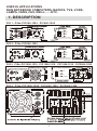
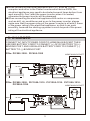
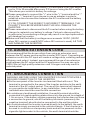
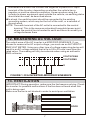
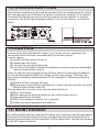
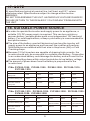
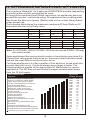
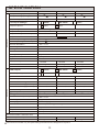
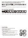
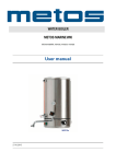
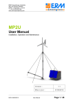
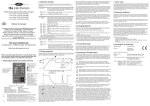
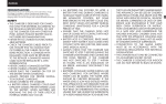
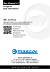
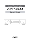
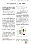
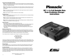
CONVERTS 12 VOLT DC TO AC
INVERTER & CHARGER
SUPERIOR 3 STAGE AUTOMATIC 12 VOLT CHARGING
INSTRUCTION MANUAL
Please read user manual before use.
USEFUL APPLICATIONS
RUN NOTEBOOK COMPUTERS, RADIOS, TVS, VCRS,
LAMPS, FANS, FAX, DRILL......ETC.
1. DESCRIPTION
FIG 1: P/No. PIC500-1205、PIC600-1205
NORMAL/FAULT
POWER ON
CHARGING/FULLY CHARGED
FIG 2: P/No. PIC800-1205
NORMAL/FAULT
POWER ON
CHARGING/FULLY CHARGED
FIG 3: P/No. PIC1000-1210、PIC1200-1210、PIC1500-1210、PIC2000-1220
NORMAL/FAULT
POWER ON
CHARGING/FULLY CHARGED
FIG 4: P/No. PIC3000-1220、PIC4000-1220、PIC5000-1220
NORMAL/FAULT
POWER ON
CHARGING
/FULLY
CHARGED
1
FIG 5:
POWER SWITCH ON
POWER SWITCH OFF
QUICK
CHARGING
SLOWLY
CHARGING
2. ACCESSORY
DC cable clips
DC cable clips
Charge AC Input plug
3.CONNECTION
◆Please verify if you have chosen the right operating voltage for both input
and output.
◆Connect the red cable from the "+" terminal (red terminal) of the battery
to the + binding post (red connection) of the inverter and the black cable
from the "-" terminal (black terminal) of the battery to the "-" binding post
(black connection) of the inverter.
◆Be sure to tighten the screws in order to avoid loose connection.
4. OPERATION
◆When connected to an appliance, remember to turn on the inverter
before turning on the appliance. If the buzzer sounds during operation,
this indicates that the battery voltage is very low and the inverter will be
disconnected in 5 minutes.
"Turn on"
secondly
"Turn on"
firstly
NORMAL/FAULT
POWER ON
CHARGING/FULLY CHARGED
2
◆When connecting electrical appliance with CRT, such as TV set,
computer and so on to the Power Inverter which below 500W, the
electrical appliance may need to be started several times before it can
work smoothly. Don't start the power inverter when it is loaded,
otherwise the power inverter will be damaged.
◆When connecting the electrical appliance with motor or compressor,
such as drill, air-conditioner and so on to the power inverter, please
make sure that the power rating of the power inverter is at least 3 times
of the power rating of the electrical appliance, so that it can work
smoothly, because the starting up power is much beyond of the power
rating of the electrical appliance.
5. CHARGER
CONNECT AC INPUT POWER CORD TO HOME MAIN SOCKET THEN
USE RED BATTERY CORD TO CONNECT (+) OF DC BATTERY TO (+)
BINDING POST. AND USE BLACK BATTERY CORD TO CONNECT (-)
BATTERY TO (-) BINDING POST.
P/No. PIC500-1205、PIC600-1205
RED
HOME MAIN SOCKET
BLACK
P/No. PIC800-1205、PIC1000-1210、PIC1200-1210、PIC1500-1210、
PIC2000-1220
HOME MAIN SOCKET
RED
BLACK
3
P/No. PIC3000-1220、PIC40000-1220、
PIC5000-1220
RED
HOME MAIN SOCKET
BLACK
SUPERIOR 3 STAGE CHARGING
BULK
ABSORPTION
FLOAT
Rapid
charge
Battery
charged
to 100%
Maintain
Superior 3 Stage Charging delivers a
faster and more powerful charge,
ideal for deep cycle batteries.
The first stage 'bulk' charges the
battery faster while the second stage
'absorption' ensures the battery is
thoroughly charged.
The final stage 'float' maintains the
battery ready for use and can be left
indefinitely.
6. AS UPS
IF YOU WANT TO USE IT AS U.P.S. TURN ON INVERTER WHEN THE
BLACKOUT HAPPENS AT THE MEANTIME. THE INVERTER WILL
AUTOMATICALLY CHANGE FROM ORIGINAL SUPPLY TO BATTERY
SUPPLY (DC-AC)
HOME MAIN SOCKET
NO RM
BLACK
AL /F
AU LT
PO W
CH AR
GI NG
ER ON
/F UL
LY CH
AR GE
D
12V
BATTERY
4
RED
7. INDICATING SIGN
GREEN/ RED LED LIGHT.
WHEN THE LED LIGHT ILLUMINATES IN GREEN COLOR, IT MEANS
THE POWER SWITCH IS IN "ON" POSITION AND INVERTER IS
WORKING NORMALLY. WHEN THE INVERTER IS AT FAULT, THE LED
LIGHT WILL ILLUMINATES IN RED COLOR.
RED LED LIGHT.
WHEN THE RED LED LIGHT ILLUMINATES, IT MEANS THE INVERTER
IS CONNECTED TO AC POWER SOURCE, BATTERY CHARGER INSIDE
IS RECEVING POWER.
ORANGE)/ GREEN LED LIGHT.
WHEN THE LED LIGHT ILLUMNATES IN ORANGE COLOR, IT MEANS
THE BATTERY IS BEING CHARGED, WHEN THE BATTERY IS FULLY
CHARGED, THE ORANGE LED LIGHT WILL EXTINGUISH AND THE LED
LIGHT WILL ILLUMINATE IN GREEN COLOR.
NORMAL/FAULT
POWER ON
CHARGING/FULLY CHARGED
NORMAL/FAULT
POWER ON
CHARGING/FULLY CHARGED
8. OUTPUT CAPACITY
The inverter will switch off automatically if the total wattage of the electrical
appliances exceed the inverter's output capacity. This will also happen if
the temperature of the inverter exceeds 65℃ +/-10% due to prolonged use.
9. SPECIAL RECOMMENDATION
◆Unplug the AC inverter when not in use.
◆Unplug the AC inverter when starting the vehicle's motor.
◆If the AC inverter makes a beeping sound: switch off your appliance,
unplug the inverter and restart your vehicle's engine. The beeping
sound implies a warning of low-battery,which indicates that the voltage
of your battery is getting low. Your inverter will shut down automatically
if you do not restart your engine and continue the use of your inverter.
This will leave your vehicle's battery at about 10.5VDC (21VDC when
using 24V inverter/42VDC when using 48V inverter), enabling you to
start your engine and resume operation of the inverter. It also eliminates
the possibility of being stranded with a dead battery.
5
◆To avoid over-discharging the battery, it is advisable to let your engine
run for 10 to 20 minutes after every 2-3 hours of using the AC inverter.
This allows your vehicle's battery to recharge.
◆Please remember to connect the "+" wire to the "+" terminal and the "-"
wire to the "-" terminal if you choose to use an adapter in order to
establish a direct connection between the AC inverter and the battery
terminals.
IF YOU CONNECT THE WIRES TO INCORRECT TERMINALS, THE
POLARITY WILL BE REVERSED AND THIS WILL DAMAGE THE
INVERTER.
◆Please remember to disconnect the AC inverter before using the battery
charger to replenish you battery's voltage. Failure to disconnect the
inverter prior to connecting a charger may result in an input spike which
will damage the inverter.
◆Make sure that the battery's voltage never exceeds 15VDC (30VDC
when 24V version is used/60VDC when 48V version is used). AS THIS
MAY DAMAGE THE INVERTER.
10. ADDING EXTENSION CORD
We recommend that the buyer refrain from using an extension cord
between the DC power source and the inverter's DC input. Connecting an
extension cord to the DC input will create a voltage drop, entailing reduced
efficiency and output. Instead, we recommend the use of an extension
cord between the AC output and the AC applicance You may use up to
100ft (30m) of high quality extension cord. A longer cord may result in
reduced power.
11. GROUNDING CONNECTION
WARNING: BEFORE USING THIS INVERTER YOU MUST PROVIDE A
GROUND CONNECTION TO THE INVERTER.
◆On the rear panel of the Inverter is a terminal fitted with a nut. This
terminal is connected to the case of the Inverter and also to the earth
terminal of the AC output socket. The use of this terminal will depend
on your particular installation. In any installation, heavy duty, greeninsulated wire should be used for this connection.
◆In a stationary land based installation, the earth terminal should be
connected to a metal earthing stake driven into the ground to a depth of
1.2m or more, If the battery system powering the Inverter does not have
a connection to ground, one of the battery terminals (commonly the
negative terminal) should also be connected to the earthing stake.
◆In a vehicle where the Inverter is wired directly to the battery, the earth
terminal is simply connected to the vehicle chassis. If the Inverter is to
be used in a vehicle on a temporary basis and will be powered via the
cigarette lighter socket in the vehicle, the earth terminal should be
6
connected via a short link to either the negative or positive DC input
terminal of the Inverter, depending on whether the vehicle has a
negative or positive chassis connection. However when using the
Inverter to power equipment used outside the vehicle, an earthing stake
should also be used, as described above.
◆In a boat, the earth terminal should be connected to the existing
grounding system, which may be the hull of the craft, or a network of
ground wires.
NOTE: The earth terminal of the AC outlet is connected to the neutral
terminal. This is the same as a standard household power point
where the neutral line is bonded to earth and there is normally no
voltage between them
12. MEASURING AC VOLTAGE
The output wave of the AC inverter is a MODIFIED SINEWAVE. If you
choose to measure the AC output voltage, you must use an AUTHENTIC
RMS VOLT METER. Using any other type of voltage measuring device will
result in an AC voltage reading that is up to 20 to 30 volts lower than the
rated value. The reading will only be accurate when using an authentic
RMS voltmeter.
VOLTS PEAK
VOLTS RMS
O
FIGURE 1: D/A INVERTER-MODIFIED SINEWAVE
13. VENTILATION
IMPORTANT! During operation, make sure the fan keeps revolving. Check
the inverter for possible malfunctions if the fan does not work when this
unit is being used.
Make sure the fan is not blocked in order to avoid poor ventilation.
BAD
GOOD
7
14. CHASSIS EARTHING
The chassis earthing lug should be connected to an earthing point, which
will vary depending on where the power inverter is installed. In a vehicle,
connect the chassis ground lug to the chassis of the vehicle. In a boat,
connect to the boat's grounding systems. In a fixed location, connect to
earth.
15.CAUTION
In case of trouble with the AC output, e.g. short-circuit, overload, etc...
the protection circuit will automatically cut off the output.
In such cases:
(A) switch off the power at once.
(B) disconnect all units.
(C) check the connected devices.
(D) use the units again unless the problems concerning the connected
devices have been solved.
When in use for a prolonged period of time, the AC output may suddenly
be cut off although the battery voltage is still very strong. This may be
caused by excessive temperatures. If this happens. Please proceed as
follows:
(A)Switch off the inverter at once.
(B)Disconnect some of the appliances or wait until the inverter cools off
Switch the inverter back on.
Always keep the inverter in an environment which is:
(A)Well-ventilated.
(B)Not exposed to direct sunlight or any other heat source .
(C)Inaccessible to children.
(D)Safe from water/moisture, oil or grease.
(E)Safe from any flammable substance.
16. MAINTENANCE
Very little maintenance is required to keep your Inverter operating properly.
You should clean the exterior of the unit periodically with a damp cloth to
prevent accumulation of dust and dirt. At the same time, tighten the screws
on the DC input terminals.
8
17. NOTE
All specifications typical at nominal line, half load, and 25℃ unless
otherwise noted. Specifications subject to change without notice.
WARNING:
DO NOT DISASSEMBLE THE UNIT. HAZARDOUS VOLTAGE! DANGER!
PLEASE RETURN TO THE DEALER IF YOU FIND ANY PROBLEM WITH
THE UNIT.
18. SUITABLE POWER SOURCE
◆In order to operate the inverter and supply power to an appliance, a
suitable 12V DC power supply is required. This can be a vehicle or
caravan battery, portable power pack or an independent 12V lead acid
battery, For most applications, a deep cycle battery is recommended for
best performance..
◆The size of the battery used will determine how long the inverter will
supply power to an appliance and how well the inverter will perform.
Most batteries are marked with their size in Amp hours (AH) or Cold
Cranking Amps.
◆Because 12 Volt inverters are capable of drawing high currents, the
inverter should only be connected to a suitable size battery, Connection
to an undersized battery could damage the battery and will result in the
inverter shutting down within a short period due to low battery voltage.
◆The amount of power dawn from the battery is proportional to the
inverter load.
P/No. PIC500-1205、PIC600-1205、PIC800-1205、PIC1000-1210、
PIC1200-1210
P/No.
PIC500-1205
PIC600-1205
PIC800-1205
PIC1000-1210
PIC1200-1210
Minimum Recommended
Battery Size
50Ah
50Ah
75Ah
75Ah
75Ah
Run time maximum load
& minimum battery size
35min
30min
20min
15min
10min
Run time for a 100 Watt
globe with minimum
battery size
4 hours
4 hours
6 hours
6 hours
6 hours
Ideal battery size
50-130Ah
50-130Ah
75-250Ah
75-250Ah
75-300Ah
P/No. PIC1500-1210、PIC2000-1220、PIC3000-1220、PIC3000-1220、
PIC400-1220、PIC5000-1220
P/No.
PIC1500-1210
PIC2000-1220
PIC3000-1220
PIC4000-1220
PIC5000-1220
Minimum Recommended
Battery Size
85Ah
85Ah
100Ah
150Ah
200Ah
Run time maximum load
& minimum battery size
7min
5min
Not
Recommended
Not
Recommended
Not
Recommended
Run time for a 100 Watt
globe with minimum
battery size
7 hours
7 hours
8 hours
12 hours
16 hours
Ideal battery size
85-400Ah
85-400Ah
100-500Ah
150-600Ah
200-700Ah
9
19. DETERMINING SUITABLE LOAD / APPLIANCES
The inverter is fitted with 1 to 2 approved EUROPEAN sockets (depending
on model) either or both sockets can be used.
As long as the combined load (Watts required to run appliance) does not
exceed the inverter' continuous rating. All appliances have a rating plate
that shows the amount of power (Watts) used or the current (Amp) drawn
under normal use.
The following table shows the maximum combined AC Amp Watts or AC
Amp which can be run by the inverter.
P/No.
PIC500-1205
PIC600-1205
PIC800-1205
PIC1000-1210
PIC1200-1210
AC combined max load (Watts)
500W
600W
800W
1000W
1200W
AC combined max load (Amps)
2.2A
2.7A
3.5A
4.4A
5.3A
Number of sockets
1
1
1
2
2
P/No.
PIC1500-1210
PIC2000-1220
PIC3000-1220
PIC4000-1220
PIC5000-1220
AC combined max load (Watts) 1500W
2000W
3000W
4000W
5000W
AC combined max load (Amps)
6.5A
8.7A
13.1A
17.4A
21.8A
Number of sockets
2
2
2
2
2
Note: For PIC4000-1220 & PIC5000-1220 do not exceed 3500W (16Amp)
per socket outlet.
Some appliances that use an electric motor or transformer may draw 2 to
6 times their rating when first turned on. these are called inductive loads
and are the most difficult tor the inverter to run.
For these appliances it is often a matter of trial and error to see what size
inverter they will run on. if in doubt always use a larger inverter. The
following table is a guide to the appropriate AC Watt drawn by various
appliances. The DC Amp column shows the approximate power drawn
from the 12 Volt supply.
※ Appliance may require larger inverter.
10
5000W
4000W
3000W
2000W
1500W
1200W
1000W
5000
4000
3000
2000
1500
1250
1000
900
750
600
500
400
350
300
250
200
175
150
100
50
800W
Small Air Compressor*/Water Heater
Small Air Compressor*/Water Heater
Larger Power Tools*/Electric Kettle
Circular Power Saw/Electric Chainsaw
Toaster/Sandwich Maker
Small Household Vacuum Cleaner
Belt Sander & other Power Tools
Small Microwave Oven (500/600W)*
Combo TV/VCR
Power Drill/Portable Grinder
Flood Lights (500W)
Submersible Pump*
Small Colour Television*
Small Power Tools/Fluorescent Light*
Juicer/Blender
Bar Fridge*/Large Stereo/PA Amplifier
Hand Mixer
Laptop Computer/Electric Knife
Portable Stereo/CD/DVD/VCR/Playstation
Charger/Mobile Phone/Camera/Camcorder
600W
Approximate
AC Watts DC Amps
500W
APPLICATION CHART
Appliance
470
380
260
175
140
95
92
83
69
50
46
37
32
28
23
19
16
12
9
5
20. HARD WIRED CONNECTION
When mounting the inverter in a vehicle, boat or cabin it may be preferable
to use longer DC battery cables than those supplied, so that the inverter
can be placed in a more convenient cooler or more protected location.
21. SPECIFICATION
P/No.
PIC500-1205
PIC600-1205
PIC800-1205
DC Input Voltage (Rated)
12V
12V
12V
DC Input Voltage (Range)
10-15V
Input Standby Current (12VDC,+/-5%)
≤0.6A
AC Output Voltage
Output Frequenc
, 45.5A
, 55A
10-15V
≤0.6A
230V~
220-240V~
50Hz
60Hz
, 73A
10-15V
≤0.6A
110V~
INVERTER
Output Regulation
+/-5% Intelligent Pwm
Output Power (Continuous Watts)
500W, 2.2A
600W, 2.7A
800W, 3.5A
Output Power (Peak Watts)
1000W
1200W
1600W
Output Waveform
Modified Sine Wave
Low Battery-Voltage Alarm (Volts)
10.5V
+/-0.5V
Low Battery-Voltage Shutdown (Volts)
10.0V
+/-0.5V
Thermal Shutdown
65℃+/-5℃
Efficiency
85-90%
Cooling Fan
Automatic temperature controlled
Overload
Shut Down & Alarm
Battery Polarity Reverse
By Fuse
Output Short
Output Short Circuit Protection
Replacement Fuse
Standard Auto Blade Fuse
Fuse Quantity & Size
3x20A
3x25A
4x25A
Fuse Location
External
External
Internal*
Connection Cable
6.0mm 2/900mm
6.0mm 2/900mm
Rated Input
Input Frequency
230V~
220-240V~
50Hz
60Hz
10.0mm 2/1100mm
110V~
CHARGER
Input Power
0.72A
0.72A
0.85A
Rated Output
12VDC, 5000mA
12VDC, 5000mA
12VDC, 5000mA
Minimum Start Voltage
4.5V
4.5V
4.5V
Current Fuse Rating (Internal)
250VAC, F2.5A
250VAC, F2.5A
250VAC, F3.15A
Current Fuse Rating (External)
250VAC, T10.0A
250VAC, T10.0A
250VAC, T10.0A
Fuse Quantity & Size
5x20mm
5x20mm
5x20mm
Type
3 Stage automatic
3 Stage automatic
3 Stage automatic
Charge Control
Bulk 5000mA (up to 14.7V)/Absorption 14.4V/Float 13.8V
Thermal Protect (fan ON)
65℃+/-5℃
Efficiency
App.85%
Battery Type
For charging 12V lead acid batteries ONLY
Performance
Micro-processing switching mode
Input Short
Input Short Circuit Protection
Output Short
Output Short Circuit Protection
Output Polarity Reverse
Output Polarity Reverse Circuit Protection
Automatic Switch / Transfer Time
AC Line to Inverter ,Inverter to AC Line / Transfer Time 10ms
Dimension (L x W x H)
255 x 212 x 67mm
255 x 212 x 67mm
360 x 212 x 67mm
Weight
2.2Kg
2.3Kg
3.0Kg
※ Internal
fuses should only be replaced by qualified electrical appliance repairer
11
SPECIFICATION
P/No.
PIC1000-1210
PIC1200-1210
PIC1500-1210
DC Input Voltage (Rated)
12V
12V
12V
DC Input Voltage (Range)
10-15V
10-15V
10-15V
Input Standby Current (12VDC,+/-5%)
≤0.65A
≤0.65A
≤0.7A
AC Output Voltage
Output Frequenc
, 91A
, 110A
230V~
220-240V~
50Hz
60Hz
, 137A
110V~
INVERTER
Output Regulation
+/-5% Intelligent Pwm
Output Power (Continuous Watts)
1000W, 4.4A
1200W, 5.3A
1500W, 6.5A
Output Power (Peak Watts)
2000W
2400W
3000W
Output Waveform
Modified Sine Wave
Low Battery-Voltage Alarm (Volts)
10.5V
+/-0.5V
Low Battery-Voltage Shutdown (Volts)
10.0V
+/-0.5V
Thermal Shutdown
65℃+/-5℃
Efficiency
85-90%
Cooling Fan
Automatic temperature controlled
Overload
Shut Down & Alarm
Battery Polarity Reverse
By Fuse
Output Short
Output Short Circuit Protection
Replacement Fuse
Standard Auto Blade Fuse
Fuse Quantity & Size
6x20A
6x25A
9x20A
Fuse Location
Internal*
Internal*
Internal*
Connection Cable
16mm 2/1100mm
16mm 2/1100mm
25mm 2/1100mm
Rated Input
Input Frequency
230V~
220-240V~
50Hz
60Hz
110V~
CHARGER
Input Power
1.30A
1.30A
1.65A
Rated Output
12VDC, 10,000mA
12VDC, 10,000mA
12VDC, 10,000mA
Minimum Start Voltage
4.5V
4.5V
4.5V
Current Fuse Rating (Internal)
250VAC, F3.15A
250VAC, F3.15A
250VAC, F3.15A
Current Fuse Rating (External)
250VAC, T10.0A
250VAC, T10.0A
250VAC, T10.0A
Fuse Quantity & Size
5x20mm
5x20mm
5x20mm
Type
3 Stage automatic
3 Stage automatic
3 Stage automatic
Charge Control
Bulk 10,000mA (up to 14.7V)/Absorption 14.4V/Float 13.8V
Thermal Protect (fan ON)
65℃+/-5℃
Efficiency
App.85%
Battery Type
For charging 12V lead acid batteries ONLY
Performance
Micro-processing switching mode
Input Short
Input Short Circuit Protection
Output Short
Output Short Circuit Protection
Output Polarity Reverse
Output Polarity Reverse Circuit Protection
Automatic Switch / Transfer Time
AC Line to Inverter ,Inverter to AC Line / Transfer Time 10ms
Dimension (L x W x H)
365 x 242 x 76mm
365 x 242 x 76mm
415 x 242 x 76mm
Weight
3.8Kg
3.9Kg
4.5Kg
※ Internal
fuses should only be replaced by qualified electrical appliance repairer
12
SPECIFICATION
P/No.
PIC2000-1220
PIC3000-1220
PIC4000-1220
DC Input Voltage (Rated)
12V
12V
12V
DC Input Voltage (Range)
10-15V
10-15V
10-15V
Input Standby Current (12VDC,+/-5%)
≤0.7A
≤0.75A
≤0.8A
AC Output Voltage
Output Frequenc
, 183A
, 275A
230V~
220-240V~
50Hz
60Hz
, 367A
110V~
INVERTER
Output Regulation
+/-5% Intelligent Pwm
Output Power (Continuous Watts)
2000W, 8.7A
3000W, 13.1A
4000W, 17.4A
Output Power (Peak Watts)
4000W
6000W
8000W
Output Waveform
Modified Sine Wave
Low Battery-Voltage Alarm (Volts)
10.5V
+/-0.5V
Low Battery-Voltage Shutdown (Volts)
10.0V
+/-0.5V
Thermal Shutdown
65℃+/-5℃
Efficiency
85-90%
Cooling Fan
Automatic temperature controlled
Overload
Shut Down & Alarm
Battery Polarity Reverse
By Fuse
Output Short
Output Short Circuit Protection
Replacement Fuse
Standard Auto Blade Fuse
Fuse Quantity & Size
12x25A
18x25A
24x25A
Fuse Location
Internal*
Internal*
Internal*
Connection Cable
25mm 2/1100mm
35mm 2/1100mm
50mm 2/1100mm
Rated Input
Input Frequency
230V~
220-240V~
50Hz
60Hz
110V~
CHARGER
Input Power
2.65A
2.75A
2..85A
Rated Output
12VDC, 20,000mA
12VDC, 20,000mA
12VDC, 20,000mA
Minimum Start Voltage
4.5V
4.5V
4.5V
Current Fuse Rating (Internal)
250VAC, F3.15A
250VAC, F3.15A
250VAC, F3.15A
Current Fuse Rating (External)
250VAC, T10.0A
250VAC, T10.0A
250VAC, T10.0A
Fuse Quantity & Size
5x20mm
5x20mm
5x20mm
Type
3 Stage automatic
3 Stage automatic
3 Stage automatic
Charge Control
Bulk 20,000mA (up to 14.7V)/Absorption 14.4V/Float 13.8V
Thermal Protect (fan ON)
65℃+/-5℃
Efficiency
App.85%
Battery Type
For charging 12V lead acid batteries ONLY
Performance
Micro-processing switching mode
Input Short
Input Short Circuit Protection
Output Short
Output Short Circuit Protection
Output Polarity Reverse
Output Polarity Reverse Circuit Protection
Automatic Switch / Transfer Time
AC Line to Inverter ,Inverter to AC Line / Transfer Time 10ms
Dimension (L x W x H)
525 x 242 x 76mm
440 x 210 x 156mm
510 x 210 x 156mm
Weight
5.8Kg
7.2Kg
8.7Kg
※ Internal
fuses should only be replaced by qualified electrical appliance repairer
13
SPECIFICATION
P/No.
PIC5000-1220
DC Input Voltage (Rated)
12V
DC Input Voltage (Range)
10-15V
Input Standby Current (12VDC,+/-5%)
≤0.9A
AC Output Voltage
Output Frequenc
, 458A
230V~
220-240V~
50Hz
60Hz
INVERTER
Output Regulation
+/-5% Intelligent Pwm
Output Power (Continuous Watts)
5000W, 21.8A
Output Power (Peak Watts)
10,000W
Output Waveform
Modified Sine Wave
Low Battery-Voltage Alarm (Volts)
10.5V
+/-0.5V
Low Battery-Voltage Shutdown (Volts)
10.0V
+/-0.5V
Thermal Shutdown
65℃+/-5℃
Efficiency
85-90%
Cooling Fan
Automatic temperature controlled
Overload
Shut Down & Alarm
Battery Polarity Reverse
By Fuse
Output Short
Output Short Circuit Protection
Replacement Fuse
Standard Auto Blade Fuse
Fuse Quantity & Size
30x25A
Fuse Location
Internal*
Connection Cable
70mm 2/1100mm
Rated Input
Input Frequency
230V~
220-240V~
50Hz
60Hz
110V~
110V~
CHARGER
Input Power
2.95A
Rated Output
12VDC, 20,000mA
Minimum Start Voltage
4.5V
Current Fuse Rating (Internal)
250VAC, F3.15A
Current Fuse Rating (External)
250VAC, T10.0A
Fuse Quantity & Size
5x20mm
Type
3 Stage automatic
Charge Control
Bulk 20,000mA (up to 14.7V)/Absorption 14.4V/Float 13.8V
Thermal Protect (fan ON)
65℃+/-5℃
Efficiency
App.85%
Battery Type
For charging 12V lead acid batteries ONLY
Performance
Micro-processing switching mode
Input Short
Input Short Circuit Protection
Output Short
Output Short Circuit Protection
Output Polarity Reverse
Output Polarity Reverse Circuit Protection
Automatic Switch / Transfer Time
AC Line to Inverter ,Inverter to AC Line / Transfer Time 10ms
Dimension (L x W x H)
505 x 210 x 156mm
Weight
9.5Kg
※ Internal
fuses should only be replaced by qualified electrical appliance repairer
14
WITH THIS "INVERTER" YOU WON'T HAVE TO WORRY
ABOUT POWER OUTAGES OR BROWNOUTS!
WARINIG:
To prevent fire shock hazard do not expose this appliance to rain or moisture.
AC OUTPUT SOCKET:
CAUTION:
ALWAYS PLACE THE INVERTER IN AN
ENVIRONMENT WHICH IS:
(A)WELL VENTILATED.
(B)NOT EXPOSED TO DIRECT SUNLIGHT OR
HEAT SOURCE.
(C)OUT OF REACH FROM CHILDREN.
(D)AWAY FROM WATER/MOISTURE, OIL OR
GREASE.
(E)AWAY FROM ANY FLAMMABLE SUBSTANCE
SECURE AND NO RISK OF FALLING.