1
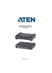
USER MANUAL FERRUPS 0800-2000 - 0800-7500 ® FERRUPS User Manual 0800-2000 through 0800-7500 2 kVA-7.5 kVA 50 and 60 Hz Uninterruptible Power Systems IMPORTANT SAFETY INSTRUCTIONS. SAVE THESE INSTRUCTIONS. This manual contains important instructions for your UPS. See the CheckUPS CD also for the FERRUPS Safety Information manual. Se cd-rommen CheckUPS til FERRUPS-manualen med sikkerhedsoplysninger. Zie de CheckUPS CD voor de FERRUPS Handleiding voor Veiligheidsinformatie. Katso CheckUPS-CD levyltä FERRUPS-turvallisuuskäsikirjaa. Se reporter à la CD CheckUPS pour le manuel de consignes de sécurité FERRUPS. Das Handbuch FERRUPS Sicherheitsinformationen befindet sich auf der CheckUPS CD. A FERRUPS Biztonsági információk kézikönyvét lásd a CheckUPS CD-n. Per le informazioni sulla sicurezza FERRUPS, vedere il CD di CheckUPS. Informasjonshåndboken om sikkerhet for FERRUPS finnes på CheckUPS CDen. Instrukcjêê bezpieczeññstwa FERRUPS mo¿¿na znnaleæ na p³³ycie CD CheckUPS. Veja no CD CheckUPS o Manual de Informações de Segurança FERRUPS. FERRUPS priroèènik informacij o varni uporabi dobite na CheckUPS zgoèenki. Ver el CD CheckUPS para el Manual de Información sobre Seguridad FERRUPS. Se CD-skivan CheckUPS CD för FERRUPS säkerhetsmanual. LTM-1319C © 1998 Best Power. All rights reserved. Best Power Offices Best Power P.O. Box 280 Necedah, WI 54646 U.S.A. Telephone: 1-608-565-7200 Toll-Free: 1-800-356-5794 (U.S.A. and Canada) FAX: 1-608-565-2221 International FAX: 1-608-565-7675 Best Power Technology Limited BEST House Wykeham Industrial Estate Moorside Road Winchester Hampshire S023 7RX ENGLAND Telephone: (44) 1962-844414 Toll-Free: 0800 378444 FAX: (44) 1962-841846 Worldwide Service P.O. Box 11 Necedah, WI 54646 U.S.A. Telephone: 1-608-565-2100 Toll-Free: 1-800-356-5737 (U.S.A. and Canada) FAX: 1-608-565-7642 Best Power Technology Germany GmbH Am Weichselgarten 23 D-91058 Erlangen Telephone: (49) 9131-77700 Toll-Free: 0130-84-7712 (in Germany) FAX: (49) 9131-7770-444 Best Power Technology Mexico, S.A. de C.V. Golfo de Riga, 34 Colonia Tacuba Mexico D.F. 11410 MEXICO Telephone: (52) 5-527-8009 Toll-Free: 1-800-711-8978 FAX: (52) 5-399-1320 Borri Elettronica Industriale Srl Via dei Lavoratori, 124 20092 Cinisello Balsamo (Mi) Milan, ITALY Telephone: (390) 2-6600661-2 FAX: (390) 2-6122481 Best Power Technology Pte. Ltd. 30 Prinsep St. #07-00 LKN Prinsep House SINGAPORE 188647 Telephone: (65) 430-6168 FAX: (65) 430-6170 Best Power Technology AG Limmatstrasse 12 8957 Spreitenbach SWITZERLAND Telephone: (41) 56-418-30-30 FAX: (41) 56-418-30-33 Sola Australia Ltd. 13 Healey Road Dandenong, Victoria 3175 AUSTRALIA Telephone: (61) 3-9706-5022 FAX: (61) 3-9794-9150 Best Power 82 Avenue des Martyrs 38000 Grenoble FRANCE Telephone: (33) (0) 4-76-86-50-90 FAX: (33) (0) 4-76-86-00-57 2 Contents 100 200 300 400 500 Introduction . . . . . . . . . . . . . . . . . . . . . . . . . . . . . . . . . . . . . . . . . . . . . . . . . . . . . . . . . . . . . . . . . . . . .3 UPS Features . . . . . . . . . . . . . . . . . . . . . . . . . . . . . . . . . . . . . . . . . . . . . . . . . . . . . . . . . . . . . . . . . . . .4 Starting the UPS . . . . . . . . . . . . . . . . . . . . . . . . . . . . . . . . . . . . . . . . . . . . . . . . . . . . . . . . . . . . . . . . . .5 Using the FERRUPS’ Front Panel Lights . . . . . . . . . . . . . . . . . . . . . . . . . . . . . . . . . . . . . . . . . . . . . . .9 Using the Display . . . . . . . . . . . . . . . . . . . . . . . . . . . . . . . . . . . . . . . . . . . . . . . . . . . . . . . . . . . . . . . . .9 501 Displaying and Moving through the Menus . . . . . . . . . . . . . . . . . . . . . . . . . . . . . . . . . . . . . . . .9 502 Displaying a Parameter by Entering the Parameter Number . . . . . . . . . . . . . . . . . . . . . . . . . . .10 Menu Map . . . . . . . . . . . . . . . . . . . . . . . . . . . . . . . . . . . . . . . . . . . . . . . . . . . . . . . . . . . . . . .11 503 Entering a Password . . . . . . . . . . . . . . . . . . . . . . . . . . . . . . . . . . . . . . . . . . . . . . . . . . . . . . . .12 504 Changing a Parameter Setting . . . . . . . . . . . . . . . . . . . . . . . . . . . . . . . . . . . . . . . . . . . . . . . . .12 505 Parameters . . . . . . . . . . . . . . . . . . . . . . . . . . . . . . . . . . . . . . . . . . . . . . . . . . . . . . . . . . . . . . . .13 506 Reading the FERRUPS Logs . . . . . . . . . . . . . . . . . . . . . . . . . . . . . . . . . . . . . . . . . . . . . . . . . .16 600 Alarms . . . . . . . . . . . . . . . . . . . . . . . . . . . . . . . . . . . . . . . . . . . . . . . . . . . . . . . . . . . . . . . . . . . . . . . .17 700 Communication . . . . . . . . . . . . . . . . . . . . . . . . . . . . . . . . . . . . . . . . . . . . . . . . . . . . . . . . . . . . . . . . .19 701 Communication Options . . . . . . . . . . . . . . . . . . . . . . . . . . . . . . . . . . . . . . . . . . . . . . . . . . . . .19 702 DB9 Port Pin Functions . . . . . . . . . . . . . . . . . . . . . . . . . . . . . . . . . . . . . . . . . . . . . . . . . . . . . .20 800 Maintenance and Service . . . . . . . . . . . . . . . . . . . . . . . . . . . . . . . . . . . . . . . . . . . . . . . . . . . . . . . . . .21 801 Regular Maintenance . . . . . . . . . . . . . . . . . . . . . . . . . . . . . . . . . . . . . . . . . . . . . . . . . . . . . . . .21 802 Service and Support . . . . . . . . . . . . . . . . . . . . . . . . . . . . . . . . . . . . . . . . . . . . . . . . . . . . . . . . .21 900 Shutting Down the FERRUPS . . . . . . . . . . . . . . . . . . . . . . . . . . . . . . . . . . . . . . . . . . . . . . . . . . . . . .22 1000 Specifications . . . . . . . . . . . . . . . . . . . . . . . . . . . . . . . . . . . . . . . . . . . . . . . . . . . . . . . . . . . . . . . . . . .23 1100 Warranty . . . . . . . . . . . . . . . . . . . . . . . . . . . . . . . . . . . . . . . . . . . . . . . . . . . . . . . . . . . . . . . . . . . . . . .25 1200 Notices . . . . . . . . . . . . . . . . . . . . . . . . . . . . . . . . . . . . . . . . . . . . . . . . . . . . . . . . . . . . . . . . . . . . . . . .28 100 Introduction This manual explains how to start your FERRUPS, interpret its status lights, use its display and communication features, and get assistance if you have a FERRUPS problem. This manual also includes specifications and warranty information. If your FERRUPS is not a soft-wired (plug-in) model, your electrician should install the FERRUPS using the Installation Manual included with your unit. If your UPS has one or more separate battery cabinets, you should also use the instructions in the Installation Manual to connect the cabinet(s) to the FERRUPS. To find information in this manual, use the contents above. Best Power is committed to outstanding customer service. If you have a problem or question, our Worldwide Service center is happy to help you. Simply refer to the list of Best Power offices at the beginning of this manual to contact the office nearest you. Please have your unit’s serial number available when you contact Best Power. (In the United States and Canada, you can call Worldwide Service toll-free at 1-800-356-5737.) You can also get more information about Best Power products using Best Power’s Fax-on-Demand service (U.S.A. and Canada only) or World Wide Web site: Fax on Demand: 1-800-487-6813 (U.S.A. and Canada) World Wide Web Site: http://www.bestpower.com 3 200 UPS Features The drawings below will help you identify the features on your UPS and separate battery cabinets. Back Panel of Standard Units* Back Panel with Optional Internal Bypass On/Off Switch DB9 Comm. Port Output Receptacles (optional) BestDock™ Communications Slot Bypass Switch On/Off Switch DB9 Comm. Port BestDock™ Communications Slot Power Cord (optional) Battery Cabinet Connector (behind plate) Optional Output Receptacles are installed here Battery Cabinet Connector (behind plate) * Only one FERRUPS model is shown; sizes vary. The unit shown is a soft-wired (plug-in) model with output receptacles; some units do not have a power cord, plug, or output receptacles. Battery Cabinet Back Panel DC (Battery Power) On/Off Switch Move Up or Increase Value UPS Display Enter Alarm Light Battery Cabinet Connection Box Battery Light Line (AC Input) Light Left Scroll, Alarm Silence, or Switch Back to Alarm Display 4 Top or Right Scroll or Alarm Clear Escape or Switch to or from Menu Move Down or Decrease Value 300 Starting the UPS Note: If you plan to store your UPS, the storage temperature must be between –20° and +40° Celsius (–4° and +104° Fahrenheit). If the UPS does not have internal batteries, you can store it at –20° to +60° C (–4° to +140° F). The batteries must be recharged every 90-120 days. To recharge the batteries, start the UPS and let it operate for 8 hours. (If the batteries are in a separate cabinet, make sure the cabinet is connected to the UPS.) Before you start the UPS, make sure the temperature is 0° to 40° Celsius (32° to 104° Fahrenheit). The relative humidity must be 0-95% without condensation. The air must be free of dust, chemicals that corrode, or other contaminants, and it must be free to move around the UPS. CAUTION To avoid possible equipment damage or personal injury, assume that the FERRUPS terminals or receptacles (outlets) may have AC voltage present whenever AC input voltage or DC battery voltage is supplied. FERRUPS can provide output voltage from its batteries even when there is no AC input voltage. When AC input voltage is available, FERRUPS can provide output voltage even when its batteries are disconnected. To make sure there will be no UPS output voltage, always disconnect the AC input source; if you have a separate battery cabinet, you must also shut off the DC switch or disconnect the battery cabinet from the UPS. To reduce the risk of electric shock, install the UPS in a temperature-controlled indoor area free of conductive contaminants. When the UPS is shipped, two sections of the front panel are not attached. Attach the front panel sections before starting the UPS. 1 When you receive the FERRUPS, two sections of the front panel are not attached. You will find the panel sections in the packing material on the top of the UPS. Attach the smaller of the two panels to the middle section. To do this, fit the slots on the back of the panel over the metal tabs on the front of the UPS. Then, push the panel in until it snaps in place. Make sure the panel is completely attached with no gaps between the panel and the UPS. Attach the larger of the two panels to the bottom section of the UPS. 2 If your UPS is not a soft-wired (plug-in) model, an electrician must install the UPS and connect the equipment you want to protect. See the FERRUPS Installation Manual. After the UPS has been installed, make sure the bypass switch is turned to “LINE,” skip step 3, and go to step 4 below. If your UPS is a soft-wired (plug-in) model, turn off the equipment you want to protect. 5 3 Plug in the UPS. If the plug on the UPS’ power cord does not match your outlet (receptacle), an electrician must install the proper outlet.If your UPS has an input connector on the back, use a cord that matches the connector and the outlet (receptacle) you will connect the UPS to. 4 If your FERRUPS has one or more separate battery cabinets, the battery packs should already be installed. (See the Installation Manual.) Find the red DC switch on the back of each battery cabinet. Insert the key into the DC switch and turn it all the way to the right (clockwise); then, pull the switch out to turn the DC on. When you want to turn the switch off, simply push it in — you do not need the key to turn DC off. 5 At the UPS back panel, press and hold the On/Off switch until the unit starts. AC input power must be present for the FERRUPS to start. When the unit starts, it is idle for a moment. Next it runs on battery power briefly; then, the green light on the FERRUPS front panel will be on to show the unit is running on AC line input. Whenever the yellow light is on, the unit is running on battery power because of a power outage or power problem. When the green light is on, the display will show the following: * Best Power * System Mode Auto Charger ON DC Switch Off On On/Off Switch Green Line (AC Input) Light FERRUPS automatically charges the batteries whenever AC input power is available. If this is the first time you’ve started the FERRUPS, let it charge the batteries for 8 hours before you go on. You can use the UPS right away, but its battery backup time (runtime) will be shorter until the batteries are fully charged. LINE 6 If your unit has a bypass switch, check for a red button next to the switch (shown). If the bypass switch has a red button, press it, then turn the switch to “UPS.” If not, simply turn the switch to “UPS.” 6 UPS SERVICE OFF 7 If your UPS has output receptacles/outlets on the back panel (shown) or on an attached internal bypass switch, plug the equipment you want to protect into the UPS’ receptacles. 8 Switch on the equipment connected to the FERRUPS. Note: If the UPS sounds an alarm and the display shows “Output Overload,” the equipment needs more power than the FERRUPS is designed to provide. See the Alarm Table in Section 600. 9 FERRUPS comes with a CheckUPS software package that lets you connect the FERRUPS to your computer and monitor UPS operation and power conditions. During longer power outages, CheckUPS also can shut down your computer automatically before the UPS runs out of battery backup time. To start using CheckUPS, find the interface cable packed with your CheckUPS software. Connect the “UPS” end of this cable to the FERRUPS’ port, and connect the other end of the cable to your computer. Power cord from the equipment you want to protect. “UPS” To your computer To install the CheckUPS software, see the instructions in the CheckUPS CD case. 10 The FERRUPS is now providing continuous, computer-grade power to your equipment. It is ready to provide battery backup power when needed. Please fill out the warranty registration card in this manual and return it to Best Power within ten days of installation. 11 When you first start the FERRUPS, you should set the time and date so that the unit’s logs keep an accurate record of FERRUPS operation. After you set the time and date once, FERRUPS’ real-time clock keeps time even when the the UPS has been completely shut down. To set the time and date, follow these steps: a. First you must enter the User password (377). To do this, follow these steps: • Press the bottom right button (below 1 1 “MENU” on the display) to switch from Enter Password the standard display to the menus. The 0000 display will show “1 Enter Password.” <– –> ESC • Press ¿. The display will show “0000” in the third line. • Notice the cursor under the first 0. Press the button under “–>” once so the cursor is under the second 0. (“–>” is on the bottom line of the display.) Then, press the s button until this number increases to 3. • Press “–>” again to move to the third digit, and press the s button until this digit increases to 7. Change the final digit to 7 as well. • The final display should show “0377”; once it does, press ¿. “USER” will appear in the upper right corner of the display to show that you have entered the User password. 7 b. Press the t button twice until the display shows “3 System Status Info.” c. Press ¿ once. The display will now show “3 1 Unit Time.” 3 1 Unit Time time 01:15 <– –> d. Press ¿. A cursor will appear in the time shown. ESC e. Notice that the bottom line of the display has changed to “<– –> ESC” to show you that you can now use the bottom three buttons to move left, move right, or escape. Use these buttons to move the cursor to each digit you need to change, and use the s and t buttons to increase or decrease each digit. Use 24-hour time (add 12 to the hour if the time is after noon). Press ¿ to save the setting. Example: If the time shown is 12:07, and the actual time is 3:15 PM, enter 15:15. Start by pressing the button below –> to move to the “2,” and press s three times to increase this to “5.” The third line of the display is now “Time 15:07.” Press the button below –> to move to the third digit (after the :), and press s once to increase this to “1.” Next, press the button below –> again to move to the next digit, and press t twice to decrease this to “5.” When you have finished, press ¿ to save the setting. f. Now, press t once to scroll down to “Unit Date.” g. Press ¿. A cursor will appear in the line “Date 01/01”. (This line may show a different date.) 3 2 Unit Date date 01/01 <– –> ESC h. As you did with the time, use the buttons below <– and –> to move to the left and right, and use the s and t buttons to increase or decrease the value of each digit in the date. Example: If the date now shown is 01/01, and you would like to change it to 07/06/98, you would use –> to move to the second digit and presss six times to increase it from “1” to “7.” Then, you would move to the fourth digit and change that to “6.” Since the other digits match the date you want to enter, you do not need to change the other digits. i. When the display shows the correct date,press ¿, and the FERRUPS date will change. j. Now, press t once to scroll down to “Unit Year.” Press ¿. A cursor will appear in the year. As you did with the time and date, use the buttonsbelow <– and –> to move to the left and right, and use the s and t buttons to increase or decrease the value of each digit in the year. k. When the display shows the correct date, press ¿, and the FERRUPS year will change. 8 3 3 Unit Year year 1998 <– –> ESC 400 Using the FERRUPS’ Front Panel Lights The FERRUPS display includes three lights that show you the status of FERRUPS operation. Alarm Light Battery Light Line (AC Input) Light The red Alarm light means the UPS has detected a problem. When this happens, the display shows an alarm message, and the UPS beeps the Morse Code for the alarm. See Section 600. The yellow Battery light means the UPS is operating on battery power, either because there is a power outage or because the available AC input power is not usable. When this happens, the display shows “System on Batteries” and the runtime. (You can press the bottom right button to switch to the menu display; see Section 501.) The UPS will continue to run on battery power until the power problem ends or the UPS’ batteries discharge. If the batteries discharge, the UPS will sound alarms shortly before shutting down. The green AC Line light means the UPS is using the available AC input power. The UPS conditions the power before providing output to your equipment. While the FERRUPS is using AC input power, it displays “System Mode Auto” and whether the battery charger is on or off. You can press the bottom right button to switch to the menu display; see Section 501 for more information. When this light is flashing, the unit is Line Condition or Battery Maintenance mode; see parameter 2 2 in Section 502. 500 Using the Display This section explains how you can use the FERRUPS’ front panel display to get more information about FERRUPS operation or to change settings. You can use the display to enter a password, display and change system settings (parameters), and display system logs. 501 Displaying and Moving through the Menus The FERRUPS display groups information in 7 different menus. See the Menu Map on page 11; the items numbered 1-7 in the left column of this diagram are the top-level menus. For example, 2 System Status is the System Status menu. To the right of this menu in the Menu Map, you will notice a list of items that are part of this menu. Some menus, like menu 5, System Config, have submenus (Gen Sensitivity; Sys Test, Inv, Chg; System Mode Control; Alarm and Shutdown; and Calibration Factors). Others simply have lists of items directly below the top level menu. When you start the UPS, the display shows “Best Power,” the mode, and whether the charger is on or off. 1 To change to the menu display, press the bottom right Enter Password s button (below the word “MENU” on the bottom line of t Top ESC the display). The display will show the top level in the first menu (1, Enter password) as shown in the drawing. Ten minutes after you last press a button, the display will switch out of menu mode and show the normal display (see Section 400). You can also switch from the top of the menu display back to the normal display by pressing the bottom right button (below “ESC”). 9 To scroll down through menus or menu items in the same level: Press the t button on the right side of the display. To scroll up through menus or menu items in the same level: Press the s button. You can also look at the bottom line of the display, which includes the words “Top” and “ESC.” The button under the word “Top” will take you to the top of the list of items in the menu level. Example: When you switch to the menu display, the display shows the top item in the top level (1, Enter password). To scroll down to menu 2 (System Status), press the t button. Press this button again to scroll down to menu 3 (System Status Info), and so forth. To scroll back up to menu 1, press s twice or press the button below “Top.” To display the items in a menu or submenu: Go to the display that represents the menu or submenu, and press the ¿ button. Example: The interface starts at the top item in the top level (1, Enter password). If you scroll down to menu 2, the display shows “System Status.” To display the items in the System Status menu, press ¿. You can then scroll down and back up through the items in this menu. To move back up a menu level: Notice that the bottom line of the display shows “Top” and “ESC.” If you press the button under “ESC” (the right button below the display), the display goes back to the next higher menu level. 502 Displaying a Parameter by Entering the Parameter Number For service purposes, parameters are also assigned sequential numbers (1-337). If you know a parameter number and want to go directly to that parameter, you can use menu 7 in the top level menus (Parameters) to display the parameter. Simply follow these steps: 1. Scroll down to menu 7, and press ¿. The third line of the display will change to “parameter # 000,” and the bottom line of the display will change to “<– –> ESC” to show the functions of the three buttons below the display. 7 Enter A Parameter parameter # 000 <– –> ESC 2. Use the <– and –> buttons to scroll through the digits to the left and right, and use the s and t buttons to increase or decrease the value of each digit. When the three digits show the number of the parameter you wish to display, press ¿. Example: To display parameter 32, you need to change the three digits (000) to “032.” Since you do not need to change the first digit, press the button below –> to move the cursor to the second digit. Then, press s three times to increase the second digit to “3.” Next, move to the third digit, and press s twice to increase this digit to “2.” Now, the display shows “parameter = 032.” Press ¿. The parameter’s short name and value will appear on the third line of the display. 10 Menu map for the User Interface 1 Enter password Key = Scrolling using up (s) and down (t) arrow buttons. Enter password = Enter (¿ ). 2 System Status 2 1 System Control 2 2 System Mode 2 3 Charger Mode 2 4 Show Alarm Code #1 2 7 Test Control 2 5 Show Alarm Code #2 2 8 Test Results 2 6 Transfer Code 2 9 Mode Flag 2 10 Alarm Test 3 System Status Info 3 3 3 3 3 3 3 3 3 13 3 14 3 15 3 16 4 System ID 5 System Config 6 System Logs 7 Parameters 1 2 3 4 Unit Time Unit Date Unit Year AC Input Volts 4 1 Model Number 4 2 Serial Number 4 3 Unit ID 5 6 7 8 AC Output Volts AC Input Current AC Output Current VA Out 3 3 3 3 4 4 Software Version 4 5 Brown Out Level 4 6 Battery Amp Hours 9 10 11 12 Watts Out % Full Load Power Factor Output Frequency 4 7 Nominal Frequency 4 8 Nominal AC V Out 4 9 Rated KVA Battery Volts Run Time Unit Ambient Temp EEPROM Stat Word 4 10 Rated KWatts 5 1 Gen. Sensitivity 511 512 513 514 Low Input Freq High Input Freq Slew Rate Line Glitch Count 515 516 517 518 Line Delta Transfer Delay Low AC Out Delay Line Full Load I 5 1 9 Circuit Brkr Trip 5 1 10 Line Cord Limit 5 2 Sys Test, Inv, Chg 521 522 523 524 525 526 527 528 Battery Test Intvl Battery Test Time 1st Date of Test Battery Test Lngth Kll Phase Offset VLLo Run Time K Fact 529 5 2 10 5 2 11 5 2 12 5 2 13 5 2 14 5 2 15 5 2 16 Run Time K Fact 2 Run Time K Fact 4 CC Minutes CV Hours Charger Rating Chrg Interval Days Chrg Duration Hrs Aux Chrg Volts On 5 2 17 5 2 18 5 2 19 5 2 20 5 2 21 5 3 System Mode Cntrol 5 5 5 5 EPO Mode EPO De-Bounce EPO Delay Startup Mode 5 5 5 5 Alarms Enable Set Relay Mask 1 Set Relay Mask 2 Set Best Port 5 3 9 Set Bestdock 5 3 10 Config BestDock 5 4 Alarm and Shutdown 5 4 1 Low Vout Shut Down 5 4 3 High Vbatt Alarm 5 4 5 Ambient Temp Alarm 5 4 2 Low Vbatt Alarm 5 4 4 Low Run Time Alarm 5 5 Calibration Factors 5 5 1 AC Vin Cal Fac 5 5 2 AC Vout Cal Fac 5 5 3 AC Iout Cal Fac 5 5 4 DC Vout Cal Fac 5 5 5 Amb Temp Cal Fac 5 5 6 Zero Amb Cal Fac 5 5 7 AC Iin Cal Fac 6 1 Data Logs 611 612 613 614 615 616 617 6 1 8 Maximum VA Out 6 1 9 Minimum Iout 6 1 10 Maximum Iout 6 1 11 Minimum Amb Temp 6 1 12 Maximum Amb Temp 6 1 13 Minimum Frequency 6 1 14 Maximum Frequency 6 1 15 Minimum Kwatts Out 6 1 16 Maximum Kwatts Out 6 1 17 Minimum Pct Load 6 1 18 Maximum Pct Load 6 1 19 Minimum Power Fact 6 1 20 Maximum Power Fact 6 2 Inverter Log 6 2 1 - 6 2 16 are the log entries. The first entry is the most recent. See Section 506. 6 3 Alarm Log 6 3 1 - 6 3 16 are the log entries. The first entry is the most recent. See Section 506. 3 3 3 3 1 2 3 4 System Hours Minimum V Battery Maximum V Battery Minimum AC Vin Maximum AC Vin Minimum AC Vout Maximum AC Vout 3 3 3 3 5 6 7 8 Enter A Parameter: parameter # 000 [Enter the parameter number to view or change.] 11 Float Chrg Voltage High Chrg Voltage Charger On Delay Install Equalize Charger Enable 503 Entering a Password Before you can change the setting of some FERRUPS parameters or menu items, you must enter a password. To do this, follow the steps below. The User password is 0377. 1. If the display is not already showing the menus, press the bottom right button (below the word “MENU” on the bottom line of the display). Go to the top item in the top menu level, “Enter Password.” (If you are not sure how to do this, see Section 502 and the Menu Map on page 11.) 2. Press ¿. The display will show the following: 1 1 Enter Password 0000 <– –> ESC A cursor will appear in the “0000” line of the display. 3. The bottom line of the display will show you which buttons to use to move through the password’s digits (0000) to the left (<–) and to the right (–>). Move the cursor to the first digit you want to change, and use the s and t buttons to increase or decrease the number. Repeat this step for each digit that needs to be changed. 4. When the number matches the password you want to enter, press ¿. The password name (such as “USER”) will appear in the upper right corner of the display to remind you which password has been entered. If you begin entering a password and decide not to enter it, press the bottom right button on the display (the button under “ESC” for escape). Example: To enter the User password (377), use the button below “–>” to move to the second digit in “0000”; then, press the s button three times to increase this digit to “3.” Next, press –> to move to the third digit, and press s seven times to increase this digit to “7.” Then, press –> again to move to the last digit, and press s seven times to increase this digit to “7.” The display should now show “0377.” This is the User password. Press ¿. “USER” will appear in the upper right corner of the display to show you the User password has been entered. 504 Changing a Parameter Setting Some of the items that you can view on the front panel display can be programmed (such as the time, date, and year). To do this, follow the steps below. (If you are changing the time and date, see step 11 in Section 300.) Note: You must enter a password before programming many of the menu items. To find out which password is required, see Section 505. To enter the password, see Section 503. 1. If the display is not already showing the menus, press the bottom right button. Find the item you want to change in the Menu Map (page 11). This tells you where the item is in the menu structure. Next, use the s, t, and ¿ buttons to move to the item you wish to change. If you are not sure how to do this, see Section 501. 2. Press ¿. If you can change the item without a password (or with the password you have already entered), a cursor will appear in the value that you can change. The bottom line of the display will change to “<– –> ESC”. Use the buttons below “<–” and “–>” to move the cursor to the left and right, and use the button below “ESC” to escape and discard any changes you have made. See the drawing on the next page, which shows what the display would look like if you were changing the time. 12 3 1 Unit Time time 0000 <– –> ESC 3. Move the cursor to the first digit you want to change, and use the s and t buttons to increase or decrease the number. Repeat this step for each digit that needs to be changed. 4. When you have finished, press ¿ to save the new setting. If you decide not to change the setting, press the bottom right button below the word “ESC” on the display. 505 Parameters The tables below provide a brief description of the parameters in the first four menus (Enter password, System Status, System Status Info, and System ID). The tables also list the range of each parameter and the password required to change its settings. Menu 5 (System Config) is mainly for service use. Section 506 explains the logs in menu 6, and Section 502 explains how to use menu 7. Menu 1: Enter Password Item and Sample Display 1 Enter Password 0000 Password to Change Range None 0000-9999 Explanation The password level. Passwords are required to change the settings of some parameters. See the “Password to Change” column in this table to determine which parameters require passwords for changes and which passwords are required. Once you enter a password, the password name appears in the upper right corner of the display. See Section 503. Menu 2: System Status Item and Sample Display Password to Change Range No change allowed. Not applicable. This hexadecimal value provides internal control signals that are not user-accessible. 2 2 System Mode sysmode Auto Service List Auto: Normal operating mode. Batt Mnt: The unit is on but cannot switch to battery power (used for battery replacement). (The green light flashes.) Line Cnd: The UPS is on but cannot switch to battery power. (The green light flashes.) Batt Pwr: The unit is using battery power. Off: The UPS is off, but you can use the display panel. Note: You cannot change the system mode to Battery Maintenance or Line Condition unless the unit is in the Auto mode and operating on line (AC input) power. 2 3 Charger Mode chgmode Const No change allowed. 2 4 No change allowed. 0-0XFFFF This is a hexadecimal alarm status value used by CheckUPS software. No change allowed. 0-0XFFFF This is a hexadecimal alarm status value used by CheckUPS software. 2 1 System Control syscon 001F hex Show Alarm Code #1 Explanation List (see The charger mode. This may be maintenance (Maint), constant explanation). voltage (Const V), constant current (Const), or periodic (Period). This parameter also includes a reserved value. almcode1 0000 hex 2 5 Show Alarm Code #2 almcode2 0000 hex 13 Menu 2: System Status (continued) Item and Sample Display Password to Change Range Explanation 2 6 Transfer Code ** reserved ** No change allowed. Reserved. This is a reserved value. 2 7 Test Control Press ¿ to Start User Not applicable. This parameter allows you to start a battery test by pressing ¿. To display the results of the test, see parameter 2 8. 2 8 Test Results O Cell - P, Batt - P No change allowed. Not applicable. This parameter shows the results of the last battery test. P = pass; F = fail. 2 9 Mode Flags modeflag 0080 No change allowed. 0-0XFFFF This is a hexadecimal system mode value. 2 10 Alarm Test Press ¿ to Start None Not applicable. By pressing ¿ while displaying this parameter, you can start a User Test alarm to make sure the FERRUPS sounds alarms properly. You can stop the User Test alarm by pressing the bottom right button (below the word “OFF”). Password to Change Range Explanation 3 1 Unit Time time 01:15 User 0001-2459 Time (displayed in 24-hour time). The FERRUPS uses this time to record alarms and battery power operation in its logs. (See Section 506.) 3 2 Unit Date date 07/08 User 0101-1231 Date. The FERRUPS uses this date to record alarms and battery power operation in its logs. (See Section 506.) 3 3 Unit Year year 1998 User 1994-2130 Year. 3 4 AC Input Volts acvin 120 V No change allowed. 65-300 The input voltage the FERRUPS is receiving. When this value drops below the brownout voltage, the FERRUPS switches to battery power. 3 5 AC Output Volts acvout 120 V No change allowed. 65-300 The voltage the FERRUPS is providing to your equipment. 3 6 AC Input Current aciin 16.7 A No change allowed. 1.0-900.0 The current the FERRUPS is drawing from the AC input source. 3 7 AC Output Current aciout 16.7 A No change allowed. 1.0-900.0 The current your equipment is drawing from the FERRUPS. 3 8 VA Out vaout 2.00 KVA No change allowed. Not applicable. Volt-amperes out. The total apparent power your equipment is drawing from the FERRUPS. This value is based on parameter 3 5 multiplied by parameter 3 7. 3 9 Watts Out watts 1.40 KW No change allowed. Not applicable. Watts out. The total real power your equipment is drawing from the FERRUPS. Menu 3: System Status Info Item and Sample Display 14 Menu 3: System Status Info (continued) Item and Sample Display Password to Change Range Explanation 3 10 % Full Load pctfload 90 % No change allowed. Not applicable. Percent of Full Load. The percentage of the FERRUPS’ total watt capacity that your equipment is using. 3 11 Power Factor powerfact 0.70 No change allowed. Not applicable. The power factor of your equipment; the difference in the way it draws voltage and current. Power factor equals Watts Out (parameter 3 9) divided by VA Out (parameter 3 8). 3 12 Output Frequency freqout 60.4 Hz No change allowed. Not applicable. During normal operation, this is the frequency of power the FERRUPS is receiving from the AC input source. If this value falls outside preset limits, the FERRUPS goes to battery power. When the FERRUPS is running on battery power, this is the frequency the FERRUPS is supplying to your equipment. 3 13 Battery Volts vbatt 48.51 V No change allowed. 10.00-70.00 The FERRUPS battery voltage. the FERRUPS will alarm if this value is too low or too high. 3 14 Run Time runtime 12 m No change allowed. Not applicable. The estimated runtime remaining, that is, the amount of time the FERRUPS will continue to support your equipment when the FERRUPS switches to battery power. The FERRUPS will alarm if this value falls below a preset limit. 3 15 Unit Ambient Temp ambtemp 23.0 C No change allowed. 0.0-150.0 The temperature (in Celsius) inside the FERRUPS. The FERRUPS will alarm and shut down if this value is too high. 3 16 EEPROM Stat Word eeword 5A0E hex No change allowed. Not applicable. A code used to identify the EEPROM configuration of parameters and logs. Password to Change Range 4 1 Model Number 0800-2000-6000 No change allowed. 5-9999 4 2 Serial Number serialno 12345678 No change allowed. 0-99999999 4 3 Unit ID unitid FERRUPS 800 No change allowed. 0-9999 This value is used by CheckUPS software. 4 4 Software Version sftwver 1.04 No change allowed. 0-9999 The version of unit software that your FERRUPS is using. 4 5 Brown Out Level brownlvl 79.8 V Service 74.4-192.0 The AC input voltage at which the FERRUPS will switch to battery power. 4 6 Batt Amp Hours batamphr 31.0 ah User 10.0-1000.0 The ampere-hour value of the FERRUPS battery strings. Menu 4: System ID Item and Sample Display Explanation The FERRUPS model number. Your FERRUPS unit’s serial number. 15 Menu 4: System ID (continued) Item and Sample Display Password to Change Range Explanation 4 7 Nominal Frequency nomfreq 60 Hz No change allowed. 50 Hz or 60 Hz The FERRUPS unit’s nominal input and output frequency. 4 8 Nominal AC V Out nomacvo 120 V User 110-260 The nominal AC output voltage the FERRUPS supplies to your equipment. For plug-in units, do not change this setting. For hard-wired units, use the setting recommended in the Installation Manual. 4 9 Rated KVA ratedva 2.00 KVA Service 0.30-20.00 The apparent power (VA or volt-amperes) that your FERRUPS is capable of supplying. 4 10 Rated KWatts ratedwts 1.40 KW Service 0.10-20.00 The real power (watts) that your FERRUPS is capable of supplying. 506 Reading the FERRUPS Logs Your FERRUPS makes an entry in its logs every time it sounds an alarm or runs on inverter (battery power). This information can help diagnose power problems. You can display both the Alarm and Inverter logs at the unit’s display panel; both logs are in menu 6. Inverter Log The Inverter Log is in menu 6, submenu 2. To display the log, follow these steps: 1. Press the bottom right button (below “Menu” on the display) to switch from the normal display to the menus. The display will show the top menu, “1 Enter Password.” 2. Press t five times (until the display shows “6 System Logs”). 3. Press ¿. The display will show “6 1 Data Logs.” 4. Press t once. The display will show “6 2 Inverter Log.” 5. Press ¿. The display will show the first entry in the inverter log. Note: If you press ¿, then the bottom middle button (labeled “CLEAR”), you can clear all inverter log entries. The log stores up to 16 entries. You can use the s and t buttons to scroll up and down through the log entries. To clear all inverter log entries, press ¿, then the bottom middle button (CLEAR). Each entry shows the inverter code, then the date the unit ran on inverter, the time (in 24-hour time), and the duration (in hours and minutes — this is 0 if less than one minute). For example, one entry might look like this: Inverter Log 1 t 0205 0951 0015 In this example, “t” means the FERRUPS went to battery power because of a battery test. (See the table below.) If the unit was still running on inverter (battery power), there would be an asterisk (*) after the “t.” “0205” means the date of the battery power operation was February 5 (2/5). “0951” means the inverter ran at 9:51 a.m. “0015” means the inverter ran for 0 hours and 15 minutes. Inverter Code t b h g m f r s Meaning Battery Test Brownout High Input Glitch Count Manual Frequency Reset Startup Explanation The FERRUPS went to inverter to test the batteries. See parameter 2 7 in Section 505. AC input voltage was too low. AC input voltage was too high. The FERRUPS detected many glitches in the input power. The inverter was started manually (by changing the system mode, parameter 2 2). Input frequency was too high or too low. The FERRUPS system was reset. The FERRUPS always runs on battery power briefly during startup. 16 Alarm Log The Alarm Log is in menu 6, submenu 3. If you have already displayed inverter log entries, press the bottom right button to display “6 2 Inverter Log,” and press t once to scroll down to the alarm log. Then press ¿. If not, follow the steps below to display the log, follow these steps: 1. Press the bottom right button (below “Menu” on the display) to switch from the normal display to the menus. The display will show the top menu, “1 Enter Password.” 2. Press t five times (until the display shows “6 System Logs”). 3. Press ¿. The display will show “6 1 Data Log.” 4. Press t twice. The display will show “6 3 Alarm Log.” 5. Press ¿. The display will show the first entry in the alarm log. Note: If you press ¿, then the bottom middle button (labeled “CLEAR”), you can clear all alarm log entries. The log stores up to 16 entries. You can use the s and t buttons to scroll up and down through the log entries. To clear all alarm log entries, press ¿, then the bottom middle button (CLEAR). Each entry shows the alarm code, then the alarm date, the alarm time (in 24-hour time), and the duration (in hours and minutes — this is 0 if the alarm lasts less than one minute). For example, one entry might look like this: Alarm Log 1 A 0205 0951 0015 In this example, “A” means the FERRUPS sounded alarm A (Low Battery). (See the alarm table in Section 600.) If the alarm was still active, there would be an asterisk (*) after the “A.” “0205” means the alarm sounded on February 5 (2/5). “0951” means the alarm sounded at 9:51 a.m. “0015” means the alarm was active for 0 hours and 15 minutes. 600 Alarms When the FERRUPS detects an alarm condition, it • sounds the Morse Code for the the alarm letter, • lights up the red light on the front panel display, • displays an alarm message. When this happens, follow these steps: 1. Check the display to find out which alarm the FERRUPS is sounding. You can also listen to the Morse Code to determine which alarm the FERRUPS has detected. Alarm Light A Low Battery vbatt 40.00 V lowbatv 40.08 V minbattv 38.34 Alarm Silence and Unsilence, or Switch Back to Alarm Display Alarm Clear MENU (Switches to Menu display) Switches between multiple alarm messages The parameters shown below the alarm message give you more information about the alarm condition. You can use the s and t buttons to scroll up and down through these parameters. • To find out if more than one alarm is active, press ¿. This switches the display between alarm messages. • To silence an alarm (or to enable an alarm you have silenced), press the left button below the display. To clear an alarm, press the bottom middle button. If the problem that caused the alarm is still present, the alarm will start again. • To switch to the MENU display, press the bottom right button. This will silence the Morse Code alarm and switch the display to the menus described in Section 500. To switch back to the alarm display, press the bottom left button (labeled “Alarms”). 17 2. Find the alarm in the table below, and follow the instructions in the third column of the table. To clear an alarm when the problem has been solved, press the middle button below the display. If the problem that caused the alarm is still present, the alarm will sound again after a short delay. Alarm Message A Low Battery vbatt 40.0 V lowbatv 41.0 V minbattv 38.34 Morse Code •— (A) What It Means How to React The UPS has shut down because the battery voltage is too low for the UPS to continue operating on battery power. The battery charge is low because the UPS was running on battery power or because the DC switch on one or more separate battery cabinets was off. Before this alarm sounded, you should have received a Low Runtime alarm (D) to warn you to shut down your equipment. Shortly after acceptable AC input power returns, the UPS will automatically restart and begin recharging the batteries. Once the UPS restarts, you can restart your equipment and resume normal operation. The battery voltage is too high. There may be a problem with the parameter settings, batteries, or charging circuit. Phone Best Power’s Worldwide Service or the nearest Best Power office. C High Battery vbatt 60.01 V hibatv 59.6 V maxbattv 60.01 V —•—• (C) D Low Runtime runtime 0 m lowruntm 3 m —•• (D) E Low AC Out acvout 220 V lowvoshdn 0 V maxva 0.00 KVA • (E) The UPS has shut down because AC output voltage is low. Shut down your equipment or bypass the UPS, and turn the UPS off. Phone Best Power’s Worldwide Service or the nearest Best Power office. F High AC Out acvout 250 V maxacvo 251 V ••—• (F) The UPS has shut down because AC output voltage is high. Phone Best Power’s Worldwide Service or the nearest Best Power office. G Output Overload pctfload 126 % ——• (G) Your equipment is drawing more power (watts) than the UPS is designed to provide. (See your model’s watt rating.) The unit will shut down after 2 minutes. The least important equipment should be disconnected from the UPS. To determine how much equipment needs to be disconnected, you can shut off the equipment one device at a time until the alarm stops. H High Ambt Temp ambtemp 75.0 c atmpalrm 70.0 c •••• (H) I Check Power Sply •• (I) J User Test The unit is running on battery power, but the Shut down your equipment and the UPS to amount of time that it can continue to do this conserve battery power. When AC input power is low. returns, turn the FERRUPS on again. If you leave the FERRUPS on after this alarm sounds, it will soon sound alarm A and shut down, and it will automatically restart a short time after AC input power returns. The temperature inside the unit is too high. If If the UPS has shut down, call Best Power’s the temperature continues to rise, the UPS Worldwide Service or the nearest Best Power will eventually shut down. office. If not, correct the cause of the high temperature, and make sure nothing is blocking the UPS vents. If you cannot correct the problem, call Best Power’s Worldwide Service or the nearest Best Power office. There is a problem with the housekeeping supply inside the UPS. If the green light on the UPS front panel is blinking, the UPS has switched to Line Condition mode, which means it cannot operate on battery power. If this happens, the UPS will not be able to supply output power during a power outage. Phone Best Power’s Worldwide Service or the nearest Best Power office. Steady tone You can start a User Test alarm by displaying To stop the User Test alarm, press the bottom parameter number 2 10 and pressing ¿. (J) right button (labeled “OFF”). Note: The menus are not accessible while this alarm is active. 18 Alarm Message Morse Code What It Means How to React K Ckt Bkr Warn (Circuit Breaker Warning) —•— (K) Your equipment is drawing more current (amps) than the UPS is designed to provide. (See your model’s output current rating.) The unit will shut down; the time until shutdown depends on the amount of overcurrent. The least important equipment should be disconnected from the UPS. To determine how much equipment needs to be disconnected, you can shut off the equipment one device at a time until the alarm stops. M Check Battery vbatt 50.00 V batamphr 85.0 ah runtimek 0.55 —— (M) The batteries have failed the automatic test. If the UPS has separate battery cabinets, make sure the DC switch is on at each cabinet. If it is, or if the UPS has no separate battery cabinets, phone Best Power’s Worldwide Service or the nearest Best Power office. N Check Inverter vbatt 50.00 V —• (N) O Memory Check mdlnum 5 ——— (O) The UPS has failed the automatic memory test. This problem could be caused by a microprocessor problem. Shut down your equipment or bypass the UPS, and turn the UPS off. Phone Best Power’s Worldwide Service or the nearest Best Power office. P EPO epomode 1 •——• (P) The Emergency Power Off feature has been activated. (See Section 701 and the Installation Manual.) To restart the UPS, press the On/Off button on the back of the FERRUPS. Then, press the bottom middle button at the front panel (Alarm Clear). ——•— (Q) The UPS has detected a problem with an MOV (Metal Oxide Varistor) inside the unit. Phone Best Power’s Worldwide Service or the nearest Best Power office. The UPS has detected a problem with the rotation of its internal fan. Phone Best Power’s Worldwide Service or the nearest Best Power office. Q Check MOV’s R Check Fan •—• (R) The UPS has detected a problem in the Phone Best Power’s Worldwide Service or the inverter, which is the circuitry that allows the nearest Best Power office. UPS to run on battery power. The UPS will not be able to run on battery power. 700 Communication 701 Communication Options Best Power offers several methods of communicating with your FERRUPS: CheckUPS Software: Each FERRUPS unit ships with CheckUPS power monitoring and unattended shutdown software. To begin installing CheckUPS, see the instructions in the CheckUPS CD case. CheckUPS uses an RS232 serial link to communicate with the FERRUPS, and it provides you with up-to-date graphics of UPS power and system data and power flow. CheckUPS also gives you a complete record of critical power events, and it notifies you of important UPS or power information. If there is a power outage and the FERRUPS battery power becomes low, CheckUPS can automatically shut down your computer system before the UPS Low Battery shutdown to protect your data. 19 Optional Interface Kits: For computer systems that already have UPS monitoring software, Best Power offers interface cable kits for connecting the FERRUPS to your computer system. Each kit includes the cable, adapters, and instructions. Optional Internal BestLink™ SNMP/WEB Adapter: Using Simple Network Management Protocol (SNMP), system administrators can easily monitor and manage remote UPS units that protect key network devices like servers, routers, and hubs. Best Power’s SNMP Adapters provide a self-contained link between the FERRUPS and an Ethernet LAN/WAN. The adapters allow the system administrator to communicate with the FERRUPS even after the protected device goes down. The SNMP adapter displays 175 Management Information Base (MIB) variables to give the system administrator information about UPS operation. In addition, BestLink creates web pages that may be viewed using Netscape or Internet Explorer. BestDock™ Emergency Power Off (EPO): FERRUPS has a communication slot that allows quick installation of an optional BestLink SNMP/WEB Adapter Card. You can connect your FERRUPS to your Emergency Shutdown switch to provide a method for emergency FERRUPS shutdown. This connection shuts down the FERRUPS output. See the Installation Manual to make the connection. 702 DB9 Port Pin Functions The table below explains the functions of the pins on the FERRUPS’ DB9 port. This port is on the FERRUPS’ back panel. The functions of pins 1 and 2 change depending on the communication mode. When you receive the UPS, it is set up for RS232 mode. However, if you want to use the alternate functions of pins 1 and 2, you can change the mode by following the steps on the next page. Pin 1 Function In RS232 mode, this pin receives incoming RS232 communication data. In Extended Contact Mode, this pin can cause a remote shutdown. If the UPS is using battery power and a +12volt DC signal is applied to this pin for 5 seconds, the UPS will shut down 120 seconds later. When the power outage ends, the UPS will automatically restart after 15 seconds. 2 In RS232 mode, this pin sends outgoing RS232 communication data. In Extended Signal mode, this pin indicates Inverter (On Battery) Status. When the UPS is using battery power, this pin produces a +12 VDC signal. When the UPS is not using battery power, this pin produces a -12 VDC signal. 3 Normally Open On Battery Contact. This is a normally open contact that closes (pulls to Common) 15 seconds after the UPS switches to battery power. This relay contact is rated at 30 VAC/DC and 0.25 A. 4 Common. This is the signal ground for all signal pins. 5 Normally Open Low Battery Alarm Contact. A normally open contact that closes (pulls to Common) during a Low Battery or Low Runtime alarm. This relay contact is rated at 30 VAC/DC and 0.25 A. 6 Not used. 7 Remote Shutdown. If this pin is shorted to common for at least 5 seconds while the UPS is operating on battery power, the UPS shuts down after 120 seconds (2 minutes). 8 Normally Closed On Battery Contact. A normally closed contact that opens (releases from Common) 15 seconds after the UPS switches to battery power. This relay contact is rated at 30 VAC/DC and 0.25 A. 9 Normally Open Bypass Switch Status Contact. A normally open contact that closes (pulls to Common) whenever the UPS is being bypassed through a bypass switch. This open collector output is rated 30 VDC and 15 mA. 20 1. a. Press the bottom right button (below “MENU” on the display) to switch from the normal display to the menus. The display will show the top menu, “1 Enter Password.” b. Press ¿. To enter the User password (377), use the button below “–>” to move to the second digit in “0000”; then, press the s button three times to increase this digit to “3.” Next, press –> to move to the third digit, and press s seven times to increase this digit to “7.” Then, press –> again to move to the last digit, and press s seven times to increase this digit to “7.” The display should now show “0377.” This is the User password. Press ¿. “User” will appear in the upper right corner of the display to show you the User password has been entered. c. Press t four times (until the display shows “5 System Config”). d. Press ¿. The display will show “5 1 Gen. Sensitivity.” e. Press t twice. The display will show “5 3 System Mode Control.” Press ¿. f. Press t seven times. The display will show “5 3 8 Set Best Port.” g. Press ¿. 2. Use the s and t buttons to scroll through the possible settings until you reach “bestport Contact”. (The other settings select a baud rate for the port in RS232 mode.) The bottom line of the display shows “<– –> ESC”. If you need to escape and discard any changes you have made, use the button below “ESC.” 3. When you have changed the setting, press ¿ to save the change. 800 Maintenance and Service 801 Regular Maintenance Best Power designed your FERRUPS to provide years of trouble-free operation. Its microprocessor will check the batteries and inverter at programmable intervals to ensure proper operation. In fact, you’ll probably find that your FERRUPS requires less maintenance than any of your other computer peripherals. Nevertheless, your FERRUPS does require some attention in order to provide you with excellent service. Best Power recommends that you schedule a Preventative Maintenance check at least every six months. At this check, the service technician should follow Best Power’s Recommended Maintenance Schedule, which includes the following: • Inspect and clean the unit. • Inspect and record the alarm and inverter logs. • Check the batteries. • Check the AC and DC meter functions and recalibrate if necessary. • Perform a system test. • Check and record the values of the parameters in menu 3 on line and on inverter. The technician must observe important safety precautions while performing these checks. For more information on what your technician should do in a Preventative Maintenance check, or to schedule Preventative Maintenance with a Best Power-authorized field service representative, call Best Power’s Worldwide Service. We’ll be happy to help you. 802 Service and Support Best Power has an outstanding customer service department. Please feel free to call, write, or fax the nearest Best Power office if you have a problem or question about your FERRUPS. Please have your model number and serial number when you call. This information appears on a label on the FERRUPS back panel. You can also get this information by displaying the serial number on the front panel display. If you are requesting repair under warranty, please include proof of purchase and purchase date in your correspondence. Call Best Power for instructions before returning a unit or component. (See the beginning of this manual for a list of Best Power offices.) 21 900 Shutting Down the FERRUPS Normally, you do not need to shut down the FERRUPS, even if your equipment will be shut down for several days. Even when it is not providing power for your equipment, the FERRUPS is charging its batteries and monitoring power conditions. However, you may need to shut down the FERRUPS for the following conditions: • When you will not be using it for an extended time. • When the FERRUPS is being serviced. • When you plan to move the FERRUPS. • When the UPS has gone into the Off mode because of battery discharge during a long power outage. • When a system problem requires you to shut the FERRUPS down. To shut down the FERRUPS, follow the steps below. CAUTION To avoid possible equipment damage or personal injury, assume that the FERRUPS terminals or receptacles (outlets) may have AC voltage present whenever AC input voltage or DC battery voltage is supplied. FERRUPS can provide output voltage from its batteries even when there is no AC input voltage. When AC input voltage is available, FERRUPS can provide output voltage even when its batteries are disconnected. To make sure there will be no UPS output voltage, always disconnect the AC input source; if you have a separate battery cabinet, you must also shut off the DC switch or disconnect the battery cabinet from the UPS. 1. Units with No Bypass Switch: Turn off the protected equipment. If you need to use the equipment while the FERRUPS is off, connect the equipment to standard wall outlets (receptacles) and restart the equipment. Go to step 2. Units with a Break-Before-Make Bypass Switch (see the label on the switch to identify it): Shut down your protected equipment. Then, turn the bypass switch to “SERVICE.” (The SERVICE position disconnects input to the UPS and output from the UPS.) LINE Turn your equipment on again if you must use it while the UPS is off. Your equipment will receive direct AC line instead of SERVICE UPS conditioned power from the UPS. Go to step 2. Units with a Make-Before-Break Bypass Switch (see the label on the switch to identify it): Press the red button to the left of the actual switch. Then, turn the switch to “SERVICE.” (The SERVICE position disconnects input to the UPS and output from the UPS.) Your equipment will receive direct AC line instead of conditioned power from the UPS. Go to step 2. OFF On/Off Switch 2. Press and hold the On/Off switch on the back of the FERRUPS until the FERRUPS shuts down. 3. If your FERRUPS has one or more separate battery cabinets, find the red keyswitch on the back of each battery cabinet, and push the switch in. This shuts off the FERRUPS’ DC source. If your FERRUPS will be off for an extended time, recharge the batteries every 90-120 days. If you do not do this, the batteries may be damaged. To restart the FERRUPS, see Section 300. 22 Push the keyswitch in. 1000 Specifications Model 0800-2000 2 kVA/1.4 kW 0800-3000 3 kVA/2.1 kW 0800-4500 4.5 kVA/3.2 kW 0800-6000 6 kVA/4.2 kW 0800-7500 7.5 kVA/5.3 kW AC Input Voltage and Current 110 = 22 amps 115 = 22 amps 120 = 22 amps 127 = 22 amps 208 = 12 amps 220 = 12 amps 230 = 12 amps 240 = 12 amps 110 = 30 amps 115 = 30 amps 120 = 30 amps 127 = 30 amps 208 = 16 amps 220 = 16 amps 230 = 16 amps 240 = 16 amps 110 = 40 amps 115 = 40 amps 120 = 40 amps 127 = 40 amps 208 = 20 amps 220 = 20 amps 230 = 20 amps 240 = 20 amps 208 = 28 amps 220 = 28 amps 230 = 28 amps 240 = 28 amps 208 = 36 amps 220 = 36 amps 230 = 36 amps 240 = 36 amps Recommended Input Service for 60 Hz U.S. Models* 120 = 30-amp 208 = 15-amp 240 = 15-amp 120 = 40-amp 208 = 20-amp 240 = 20-amp 120 = 50-amp 208 = 25-amp 240 = 25-amp 208 = 35-amp 240 = 35-amp 208 = 45-amp 240 = 45-amp Output Voltage and Maximum Output Current in Amps** 120 = 16 amps 127 = 15 amps 208 = 9 amps 220 = 9 amps 230 = 8 amps 240 = 8 amps 120 = 25 amps 127 = 23 amps 208 = 14 amps 220 = 13 amps 230 = 13 amps 240 = 12 amps 120 = 37 amps 127 = 35 amps 208 = 21 amps 220 = 20 amps 230 =19 amps 240 = 18 amps 120 = 50 amps 127 = 47 amps 208 = 28 amps 220 = 27 amps 230 = 26 amps 240 = 25 amps 120 = 62 amps 127 = 59 amps 208 = 36 amps 220 = 34 amps 230 = 32 amps 240 = 31 amps Efficiency on AC Line 90% 90% 90% 89% 89% On Line BTU/hour: kW/hour: 703 0.206 1024 0.300 1427 0.418 1707 0.500 2116 0.620 Audible Noise (dB) <55 dB <55 dB <55 dB <55 dB <55 dB 17 minutes 36 minutes 10 minutes 22 minutes 16 minutes 38 minutes 12 minutes 27 minutes Typical Standard Runtime (minutes) Full Load: 11 minutes Half Load: 23 minutes Weights: No Internal Bypass, Standard Batteries: 60 Hz Units: 50 Hz Units 280 lbs. (127 kg) 280 lbs. (127 kg) 323 lbs. (146.5 kg) 330 lbs. (149.7 kg) 377 lbs. (171 kg) 402 lbs. (182.3 kg) 600 lbs. (272.2 kg) 631 lbs. (286.2 kg) 655 lbs. (297.1 kg) Internal Bypass, Standard Batteries: 60 Hz Units: 50 Hz Units 303 lbs. (137.4 kg) 303 lbs. (137.4 kg) 350 lbs. (158.8 kg) 357 lbs. (161.9 kg) 406 lbs. (184.2 kg) 431 lbs. (195.5 kg) 629 lbs. (285.3 kg) 660 lbs. (299.4 kg) 684 lbs. (310.3 kg) Battery Cabinet, Standard Batteries: FBT21 FBT22 FBT31 FBT32 235 lbs. (106.6 kg) 355 lbs. (161.0 kg) 418 lbs. (189.6 kg) 660 lbs. (299.4 kg) 235 lbs. (106.6 kg) 355 lbs. (161.0 kg) 418 lbs. (189.6 kg) 660 lbs. (299.4 kg) 235 lbs. (106.6 kg) 355 lbs. (161.0 kg) 418 lbs. (189.6 kg) 660 lbs. (299.4 kg) 235 lbs. (106.6 kg) 355 lbs. (161.0 kg) 418 lbs. (189.6 kg) 660 lbs. (299.4 kg) 235 lbs. (106.6 kg) 355 lbs. (161.0 kg) 418 lbs. (189.6 kg) 660 lbs. (299.4 kg) UPS Dimensions (without bypass) (H x W x D) UPS Dimensions with Internal Bypass (H*** x W x D) Battery Cabinet Dimensions (H x W x D) 27.25 x 13.5 x 28.5 inches 695 x 345 x 725 mm 30.5 x 13.5 x 25 in 775 x 347 x 635 mm 38.75 x 13.5 x 32.5 inches 985 x 345 x 825 mm 28.6 x 13.5 x 35 inches 730 x 345 x 890 mm 31.9 x 13.5 x 31.5 in 810 x 347 x 800 mm 40.1 x 13.5 x 39 inches 1020 x 345 x 990 mm FBT21, FBT22: 27.25 x 13.5 x 28.5 in. (695 x 345 x 725 mm); add 2.6 in/66 mm to depth for connection box. FBT31, FBT32: 38.75 x 13.5 x 32.5 in. (985 x 345 x 825 mm); add 2.6 in./66 mm to depth for connection box. * Size input protection according to all applicable local or national codes. Fuse and circuit breaker sizes vary. Sizes shown are for the U.S. and Canada. ** At 0.7 leading or distortion power factor. Size output protection according to all applicable local or national codes. *** Height includes switch. 23 AC Output with Nominal Input Power and Loads (Protected Equipment) Voltage Regulation: ±3% load regulation. Total voltage regulation under any line, load, or battery condition to within –8.3% and +5% of nominal. Input Voltage Range: At low voltages: 85-135 VAC. At high voltages: 165-275 VAC. Overload Capability: 150% surge and 125% for 10 minutes. Sine-wave Power: FERRUPS provides sine-wave, computer-grade power with 5% or less total harmonic distortion at rated load. It meets or exceeds CSA C22.2 No. 107.1. Output Frequency: On line: 60 Hz or 50 Hz. On inverter: 60 Hz or 50 Hz ±0.1 Hz. Output frequency tracks input line frequency up to limit, which is adjustable from ±0.1 Hz to ±5 Hz. FERRUPS switches to battery power if line frequency exceeds the selected limit. Lightning and Surge Protection Tested in accordance with ANSI/IEEE C62.41 Category A (6000 volt spike and 200 amp) and Category B (6000 volt spike and 3000 amp) test, and ANSI/IEEE C62.45 test procedures, and per EN61000-4-4 and EN 61000-4-5. Isolation and Noise Rejection Isolation, Including Output Neutral-to-Ground Bonding: FERRUPS provides a true separately derived power source as defined by National Electrical Code Article 250-5d, with output neutral bonded to ground. There is no direct connection between input and output. RF Noise Isolation: Common Mode: £ 120 dB. Differential Mode: £ 60 dB. Environment Operating Temperature: Operating: 0° to 40° Celsius (32° to 104° F) and 95% relative humidity. Storage Temperature: UPS with batteries inside: –20° to +40° Celsius (–4° to 104° F). UPS without batteries: –20° to +60° Celsius (–4° to 140° F). See Section 200. Relative Humidity: 0-95% without condensation. High Altitude Operation: The maximum operating ambient temperature drops 1° C per 300 m above sea level (2°F per 1000 ft. above sea level). Maximum elevation is 3000 m (10,000 ft.). Ventilation: The air around the UPS must be clean, dust-free, and free of corrosive chemicals or other contaminants. The FERRUPS uses internal fans to circulate the air for cooling. The air must be free to circulate around the UPS and battery cabinet(s). 24 Protection DC Input: DC fuse and battery charger overvoltage limit network. Output Protection: The ferroresonant transformer inherently limits current and provides overload protection. FERRUPS has high AC and low AC output voltage alarms, as well as an overload alarm. If the AC output voltage falls below the low AC output voltage alarm setpoint, the unit will alarm after 5 seconds. If the AC output voltage falls below the low AC output shutdown setpoint, the unit will alarm and shut down. Batteries and Battery Charger Standard batteries are sealed, gas recombinant, and lead-acid, especially designed for UPS use. 2 kVA to 7.5 kVA: Nominal battery voltage is 48 VDC. The standard battery charger is rated at 10 amperes at 48 VDC. Optional battery chargers at higher current ratings are available. Call the nearest Best Power office for more information. Agency Listings and Compliance 60 Hz Models: UL and cUL listed, NOM certified. 2-3 kVA with input plugs/line cords comply with FCC Class B and ICES Class B. Hard-wired 2-3 kVA models and all 4.5-7.5 kVA models comply with FCC Class A and ICES Class A. 50 Hz Models: TÜV certified, CE. 2-3 kVA models comply with EN 50091-2 Class B. 4.5-6.0 kVA models comply with EN 50091-2 Class A. 1100 Warranty LIMITED TWO YEAR WARRANTY Standard Warranty For All Purchases BEST POWER, a division of General Signal Power Systems, Inc. (hereinafter called BEST POWER) warrants that each product sold by BEST POWER is compatible with existing commercially available computer equipment with enclosed power supplies and is free from defects in materials and workmanship under normal use and service. This warranty is applicable only to the initial retail purchaser (PURCHASER), and is not transferable. The duration of this warranty is two (2) years from the date of the first retail sale or the date of delivery to the PURCHASER, whichever occurs first, subject to the following conditions. If the PURCHASER discovers within the duration of this warranty a failure of the product to perform compatibly with presently existing computer equipment or a defect in material or workmanship, the PURCHASER must promptly notify BEST POWER in writing within the duration of the warranty or not later than one month after expiration of the warranty. BEST POWER’s obligation under this warranty is limited to the replacement or repair, subject to the conditions specified below, of such product returned intact to BEST POWER which shall appear to BEST POWER, upon inspection, to have been either 25 incompatible or defective. Replacement or repair will be made at BEST POWER’s Worldwide Service, Highway 80, Necedah, Wisconsin 54646, U.S.A. Such repair or replacement shall be at BEST POWER’s expense. This warranty does not cover any taxes which may be due in connection with replacement or repair, nor any installation, removal, transportation or postage costs. These expenses will be paid by PURCHASER. If BEST POWER is unable to repair or replace the product to conform to this warranty after a reasonable number of attempts, BEST POWER will refund the purchase price. Remedies under this warranty are expressly limited to those specified above. TO THE EXTENT ALLOWED BY LAW, BEST DISCLAIMS ALL OTHER WARRANTIES, EXPRESS OR IMPLIED, INCLUDING, BUT NOT LIMITED TO, ANY IMPLIED WARRANTIES OF MERCHANTABILITY OR FITNESS FOR A PARTICULAR PURPOSE, AND ANY IMPLIED WARRANTY OF MERCHANTABILITY OR FITNESS FOR A PARTICULAR PURPOSE ON THIS PRODUCT IS LIMITED IN DURATION TO THE DURATION OF THIS WARRANTY. TO THE EXTENT ALLOWED BY LAW, BEST POWER SHALL NOT BE LIABLE FOR ANY SPECIAL, INCIDENTAL, OR CONSEQUENTIAL DAMAGES INCLUDING, BUT NOT LIMITED TO, LOSS OF PROFITS, INJURIES TO PROPERTY, LOSS OF USE OF THE PRODUCT OR ANY ASSOCIATED EQUIPMENT. Some states do not allow limitations on how long an implied warranty lasts, so that the above limitation on duration of implied warranties may not apply to you. Some states do not allow the exclusion or limitation of incidental or consequential damages, so the above limitation or exclusion may not apply to you. This warranty gives you specific legal rights, and you may also have other rights which vary from state to state. You are advised to consult applicable state laws. No warranty is made with respect to other products sold by BEST POWER which do not bear the name BEST POWER, and no recommendation of such other product shall imply or constitute any warranty with respect to them. This warranty does not cover repair or replacement because of damage from unreasonable use (for example only, damage from road hazard, accident, fire or other casualty, misuse, negligence, or incorrect wiring) and any use or installation not in conformance with instructions furnished by BEST POWER, or repairs or replacements needed because of modifications or parts not authorized or supplied by BEST POWER. LIMITED WARRANTY Transient Voltage Surge Suppression Circuitry (For U.S. and Canadian Purchasers Only) BEST POWER, a division of General Signal Power Systems, Inc. (“BEST POWER”) hereby warrants the transient voltage surge suppression circuitry in each FERRUPS®, FORTRESS®, PATRIOT®, UNITY/I™, CITADEL®, or SPIKEFREE product (hereinafter called “Product”) sold by it for installation in the United States of America and Canada to be free from defects in material and workmanship under normal use and service for the lifetime of the Product, beginning with the date of sale to the initial retail purchaser, subject to the following conditions. This warranty is applicable only to the initial retail purchaser (hereinafter called PURCHASER), is not transferable, and is limited to the following remedies: 1. The replacement or repair of the transient voltage surge suppression circuitry in each Product that is returned intact to BEST POWER and which shall appear to BEST POWER upon inspection to have been defective in material or workmanship or to have been damaged through normal use; 2. The reimbursement to the PURCHASER of up to $25,000 per occurrence of documented physical damage to specified computer equipment connected to a Product where such damage could have been prevented by transient voltage surge suppression circuitry as detailed in BEST POWER’s specification for the Product sold. This warranty is made in addition to BEST POWER’s Limited Two Year Warranty. 26 This warranty does not include any taxes which may be due in connection with replacement or repair nor any installation, transportation or postage costs. These expenses will be paid by PURCHASER. Replacement or repair will be made at BEST POWER’s Worldwide Service, Highway 80, Necedah, Wisconsin 54646, U.S.A. This warranty does not cover repair or replacement because of damage from unreasonable use (damage from road hazards, accident, fire or other casualty, misuse, negligence, incorrect wiring) and any use or installation not in conformance with instructions furnished by BEST POWER, or repairs or replacements needed because of modifications or parts not authorized or supplied by BEST POWER. This warranty is operable only upon the written acceptance by BEST POWER of an application by the PURCHASER on BEST POWER’s standard form for the above warranty coverage for the Product sold. In such application, the PURCHASER shall represent that the Product sold has been properly installed and grounded in accordance with instructions received from BEST POWER, and the PURCHASER shall also specify the computer equipment to which the Product sold has been connected and the location of the computer equipment. This warranty will not apply to any equipment not specified in the application by the PURCHASER as protected equipment. EXCEPT AS EXPRESSLY SET FORTH IN THIS WARRANTY AND BEST POWER’s LIMITED TWO YEAR WARRANTY, BEST POWER MAKES NO OTHER WARRANTIES, AND TO THE EXTENT ALLOWED BY LAW, BEST DISCLAIMS ALL OTHER WARRANTIES, EXPRESS OR IMPLIED, INCLUDING, BUT NOT LIMITED TO, ANY IMPLIED WARRANTIES OF MERCHANTABILITY OR FITNESS FOR A PARTICULAR PURPOSE. REMEDIES UNDER THIS WARRANTY ARE EXPRESSLY LIMITED TO THE REPAIR OR REPLACEMENT OF PRODUCTS AND THE REIMBURSEMENT SPECIFIED ABOVE, AND TO THE EXTENT ALLOWED BY LAW ANY CLAIMS FOR LOSS ARISING OUT OF THE FAILURE OF PRODUCTS TO PERFORM FOR ANY PERIOD OF TIME, OR SPECIAL, INDIRECT, INCIDENTAL OR CONSEQUENTIAL DAMAGES OR OTHER ECONOMIC LOSS ARE EXPRESSLY EXCLUDED. Some states do not allow limitations on how long an implied warranty lasts, so that the above limitation on duration of implied warranties may not apply to you. Some states do not allow the exclusion or limitation of incidental or consequential damages, so the above limitation or exclusion may not apply to you. This warranty gives you specific legal rights, and you may also have other rights which vary from state to state. You are advised to consult applicable state laws. 27 1200 Notices 2-3 kVA models with input plugs and line cords: This device complies with part 15 of the FCC rules. Operation is subject to the following two conditions: (1) This device may not cause harmful interference, and (2) this device must accept any interference that may cause undesired operation. Note: This equipment has been tested and found to comply with the limits for a Class B device pursuant to part 15 of FCC rules. These limits are designed to provide reasonable protection against harmful interference when this equipment is operated in a commercial environment. This equipment generates, uses, and can radiate radio frequency and, if not installed and used in accordance with the instruction manual, may cause harmful interference to radio communications. However, there is no guarantee that interference will not occur in a particular installation. If this equipment does cause harmful interference to radio or television reception, which can be determined by turning the equipment off and on, the user is encouraged to try to correct the interference by one or more of the following measures: • Reorient or relocate the receiving antenna. • Increase the separation between the equipment and the receiver. • Connect the equipment into an outlet on a circuit different from that to which the receiver is connected. • Consult the dealer or an experienced radio/TV technician for help. Changes or modifications not expressly approved by the party responsible for compliance could void the user’s authority to operate the equipment. This Class B interference causing equipment meets all requirements of the Canadian Interference Causing Equipment Regulations ICES-003. Cet appareil numerique de la Classe B respecte toutes les exigences du Reglement sur le materiel brouileur du Canada. Hard-wired 2-3 kVA Models and All 4.5-7.5 kVA Models: Note: This equipment has been tested and found to comply with the limits for a Class A digital device pursuant to Part 15 of FCC rules. These limits are designed to provide reasonable protection against harmful interference when this equipment is operated in a commercial environment. This equipment generates, uses, and can radiate radio frequency energy and, if not installed and used in accordance with the instruction manual, may cause harmful interference to radio communications. Operation of this equipment in a residential area is likely to cause harmful interference, in which case the user will be required to correct the interference at his/her own expense. Changes or modifications not expressly approved by the party responsible for compliance could void the user’s authority to operate the equipment. This Class A interference causing equipment meets all requirements of the Canadian Interference Causing Equipment Regulations ICES-003. Cet appareil numerique de la Classe A respecte toutes les exigences du Reglement sur le materiel brouileur du Canada. 28 EC Declaration of Conformity 98 We, declare under sole responsibility that the following equipment: Equipment Type: Uninterruptible Power Supply and Accessories Model(s): 0800-2000-5, 0800-3000-5, 0800-4500-5, 0800-6000-5, 0800-2000-6, 0800-3000-6, 0800-4500-6, 0800-6000-6, 0800-7500-6, FBT20, FBT21, FBT22, FBT30, FBT31, FBT32, BPE12 and BPE14 All model numbers may be followed by up to four alphanumeric characters. Models to which this declaration relates, are in conformity with the following standards: Harmonized Standards Used: EN 55022 : 1987 Limits and methods of measurement of radio interference characteristics of ITE EN 50081-1 : 1992 Electromagnetic compatibility - Generic emission Part 1. Residential, commercial and light industry EN 50082-1 : 1992 Electromagnetic compatibility - Generic immunity Part 1. Residential, commercial and light industry EN 50091-2 : 1996 Uninterruptible power systems (UPS) Part 2. EMC requirements Other Standards Used: IEC 801-2 : 1991 Part 2. Electrostatic discharge requirements IEC 801-3 : 1984 Part 3. Radiated electromagnetic field requirements IEC 801-4 : 1988 Part 4. Electrical fast transient/burst requirements IEC 801-5 : 1996 Part 5. Immunity Surge, Level 3, 2kV per the provisions of the Electromagnetic Compatibility Directive 89/336/EEC of 3 May 1989 as amended by 92/31/ECC of 28 April 1992 and 93/68/ECC, Article 5 of 22 July 1993, and, Harmonized Standards Used: EN 60950 : 1992 Safety of information technology equipment, and Amendments A1, A2, A3, A4, A11 EN 50091-1-1 : 1996 Uninterruptible power systems (UPS) and Amendments, A1 Part 1. General safety requirements per the provisions of the Low Voltage Directive 73/23/EEC of 19 February 1973 as amended by 93/68/EEC, Article 13 of 22 July 1993 Signature of manufacturer or responsible party: Name/Title of Signatory: Ming Kuo/Director of Engineering Best Power P.O. Box 280, Necedah, WI 54646 Signature of responsible party: Name/Title of signatory: Ian Haddon/Managing Director Best Power Technology Limited Wykeham Industrial Estate Moorside Road Winchester Hampshire SO23 7RX England 29