1
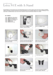
User Manual
1.
Safety:
a. General
i. WEAR EYEGUARDS: It is strongly recommended that
eyeguards be worn by anyone using the Knight Trainer or
standing on the court with the Knight Trainer. People
near the Knight Trainer may be hit by shuttles returned
by the player(s) using the machine.
ii. POWER DOWN: During examination, servicing or
maintenance of the Knight Trainer, turn off the power switch and unplug the Knight
Trainer.
iii. USE ONLY AS INTENDED: Only use the Knight Trainer to feed and eject regulation
badminton shuttlecocks, whether nylon or feather.
iv. USE SAFELY: Do not operate the Knight Trainer with the transparent panels removed.
b. During setup or takedown
i. The stand
1. LOWEST POSITION: Be sure that the stand is in
its lowest position.
2. HANDLE WITH CARE #1: Do not place your
hands where they can be caught by the scissor
action of the brackets as they open or close.
3. HANDLE WITH CARE #2: As the stand’s legs close
towards the outer shaft, do not place your
hands where they can be caught by the legs.
ii. The Knight Trainer
1. 2 PEOPLE: when placing the Knight Trainer on
the stand, or removing it from the stand, ideally
2 people should work together.
2. WATCH YOUR STEP: Make sure that the area around the Knight Trainer is clear so as
to avoid stumbling while handling the unit.
3. FIRM GRIP: Whether working alone or with someone else, be very sure of your grip
on the Knight Trainer while either positioning it on the central shaft of the stand, or
removing it from the stand.
c. During operation of the Knight Trainer
1. Wear eyeguards.
2. Use an extension cord of sufficient length (see section 2)
3. Unless otherwise instructed, unplug the Knight Trainer from the power supply before
any examination of, or contact with, the feeding and ejection mechanisms
4. Do not stand directly in front of an operating Knight Trainer.
5. Do not lean on the Knight Trainer.
6. Turn off the feeding mechanism before inserting or removing a tube containing
shuttlecocks.
Knight Trainer Manual v3.9.doc
PDF created with pdfFactory trial version www.pdffactory.com
Page 1 of 18
User Manual
2.
Electrical requirements
The Knight Trainer is configured to operate at 120 V, 60 Hz, 5 Amps, and is suitable for standard
current in Canada and the US. A compact transformer is available as an option for any Knight
Trainers shipped to countries with different electrical requirements.
You will need an appropriate extension cord long enough to reach from an electrical outlet to the
net while lying flat on the court floor for the whole distance. This extension will be connected to the
power cord supplied with the Knight Trainer and will allow you a full range of positions on the court.
If you are using a transformer, the transformer should be located at the electrical outlet.
The remote control requires 2 AAA batteries (included).
3.
Preliminaries
What kind of shuttlecocks can be used with the Knight Trainer?
The Knight Trainer has been designed to work best with nylon and feather shuttlecocks with cork
bases. It will work with nylon shuttles with either foam or synthetic corks but has only been
extensively tested with natural cork.
For nylon shuttlecocks, we have found that the cork construction of some popular brands is not
suitably durable and that corks will separate with little use. Therefore, the Black Knight nylon models
Truflight 3000 and Truflight 4000 are strongly recommended for use with the Knight Trainer. These
models have been designed with the Knight Trainer in mind, and will last much longer than many
other brands, while offering top level playability.
However, we have found satisfactory performance with many brands of feather shuttlecocks.
Will the Knight Trainer work with used shuttlecocks?
The Knight Trainer will work with used shuttlecocks as long as their condition will allow them to feed
properly. Feather shuttlecocks with broken feathers are more likely to snag another shuttle, in which
case two might be ejected together.
Bear in mind that shot quality and shot consistency are best with shuttlecocks in good condition.
Shuttles in bad condition are best for drills where accuracy is not as important.
Should feather shuttlecocks be humidified?
For longest life, feather shuttlecocks should always be humidified. With the Knight Trainer, you can:
- Use steam to humidify shuttles in their original shuttle tubes and then transfer to the
Knight Trainer’s feeding tubes. Do not use hot steam directly into the Knight Trainer’s
feeding tubes as the heat will damage the plastic.
o Don’t over steam – the goal is to put some moisture in the tube that the shuttles
can absorb slowly, and to leave the shuttles to do so while cooling after
steaming.
Knight Trainer Manual v3.9.doc
PDF created with pdfFactory trial version www.pdffactory.com
Page 2 of 18
User Manual
-
Store feather shuttles in the Knight Trainer tubes, with something moist (but not too wet)
just inside the orange end cap (such as a sponge). Air out the tube bag and tube from
time to time to avoid mold.
Will the Knight Trainer damage the shuttles?
The Knight Trainer ejects the shuttles by grabbing the cork and makes minimal contact with the
feathers or nylon cage, so damage to the cage by the Knight Trainer is very rare. Shuttles will be
damaged by players hitting the shuttles, as is normally the case in play or training. Feather shuttles
will always last longer if humidified.
You will see signs of wear on the cork, such as abrasion and wearing away of the cork’s cover, and
some compression of the cork. These changes do not affect flight.
Due to the compression of the cork, some corks may eventually break while the feathers or nylon are
still intact. If there is persistent cork breakage, this may require increasing the wheel spacing in order
to reduce the pressure (refer to the troubleshooting section) or changing the brand or model of
shuttlecock being used (see 3 above concerning nylon shuttlecocks).
Can the Knight Trainer automatically vary shots?
Once the Knight Trainer has been set for a particular shot, it will repeat that shot with a small range
of variability in the trajectory. The Knight Trainer has been designed to offer a steady repetition of
quality shots. Coaches and players of all levels can take advantage of this to improve and increase
their repertoires of shots, and to steadily improve accuracy in placement.
4.
Setting up the Knight Trainer
The complete Knight Trainer kit includes:
- The Knight Trainer unit itself containing the feeding and ejection systems
- A power cord to plug into the Knight Trainer’s control panel and to connect to the user’s own
extension cord
- A wheeled sports bag with a 2” polyethylene base in which the Knight Trainer can be transported
locally. This bag is not intended to protect the Knight Trainer during shipping. For that purpose, keep
and re-use the original shipping carton in which the Knight Trainer was delivered to you.
o When you receive the Knight Trainer, handle the packing foam carefully so as not to break it
apart and to ensure that it will be reusable if needed.
o The sports bag includes a shoulder strap. Do not use the shoulder strap to carry the Knight
Trainer.
- The stand, with 3 wheels
- A transport bag for the stand
- Three 50” (1.27 m) tubes to hold approximately 50 shuttlecocks each. Each tube includes:
§ An exit cap, already in place, and shaped to allow the shuttles to be drawn from the
tube.
§ An end cap, which closes the opposite end of the tube.
- A transport bag for those tubes
- A weighted ball for the shuttle tube that is in use
- Three pairs of eyeguards
Knight Trainer Manual v3.9.doc
PDF created with pdfFactory trial version www.pdffactory.com
Page 3 of 18
User Manual
-
Two remote controls (one being a spare), including 2 AAA batteries and a small nylon drawstring bag
to store the control (this can conveniently be hung from one of the stand’s knobs).
A spacer to allow verification of the distance between the ejection wheels. See the maintenance
section for information on using the spacer and how to make any necessary adjustments.
a. Knight Trainer’s Stand
(Steps with * are only applicable
the first time the stand is used)
i. *Remove the stand from the box,
including the plastic bag
containing three wheels and a
wrench.
ii. There are two collars on the outer
shaft, each with a locking knob (A
and B). Turn each knob
counterclockwise to ensure that
the collars will move freely on the
outer shaft.
iii. Turn the stand upside down.
*Some force will be required
initially to release each leg from the position in which it was packed, in order to expose the
threaded holes into which the wheels will be screwed
iv. *Use the wrench to screw a wheel into the threaded hole on each leg of the stand
v. Place the stand, wheels down, on the floor.
vi. Press down on the upper collar and allow the three legs to spread outwards.
vii. When the legs are fully extended, adjust the outer shaft so that the bottom of the shaft is about
1” off of the floor.
viii. Tighten the locking knob (A and B) on each collar
b. Knight Trainer main unit (feeding/ejection assembly)
Although compact, the Knight Trainer weighs over 50
pounds (23 kg). Therefore it is best to have two people
installing the Knight Trainer on the stand or removing it.
i. Ensure that the stand is at its lowest position.
ii. Ensure that the angle locking knob (see picture
below) has been tightened so that the Knight
Trainer will not rotate on the main bracket.
iii. Depress the levers on the tripod wheels to lock
the wheels into position so that the stand will
not roll during installation.
iv. Ensure that the power cord is not plugged into
the Knight Trainer.
v. Grasp the Knight Trainer by the handle and by
the main bracket - do not grasp the Knight
Trainer by the polycarbonate covers.
vi. Lift the Knight Trainer and position the main bracket’s cylinder above the top of the stand’s
central shaft.
Knight Trainer Manual v3.9.doc
PDF created with pdfFactory trial version www.pdffactory.com
Page 4 of 18
User Manual
vii. Lower the Knight Trainer so that the bracket’s cylinder descends over the central shaft and the
Knight Trainer settles into position.
viii. Loosen the angle locking knob and change the angle appropriately
ix. Unlock the stand’s wheels so that the Knight Trainer can be easily moved around the court.
c. Shuttlecock feeding tubes
i. The tubes are ready for use as delivered. Please see the following section for more details.
ii. Note that the tubes should not be exposed to temperatures over 75°C (170°F) or they may soften
and become misshapen. Therefore do not apply steam to shuttles in the feeding tubes, and do not
leave them where they can be exposed to such temperatures.
Knight Trainer Manual v3.9.doc
PDF created with pdfFactory trial version www.pdffactory.com
Page 5 of 18
User Manual
5.
Operating the Knight Trainer
a. Placing the tube of shuttlecocks
The Knight Trainer is delivered with 3 tubes to hold shuttlecocks. These tubes can each hold
approximately 50 nylon or feather shuttles.
i. Ensure that the feeding mechanism is turned off. The ejection motors can remain powered up.
ii. The provided ball can be placed inside the tube at the top of the stack of shuttles to ensure
sufficient weight to press the last few shuttles into position, especially when the tube angle is
farthest from vertical.
iii. Lower the tube, with the cork end of the shuttlecocks facing down, through the tube bracket
iv. Ensure that the tube is seated as far into the bracket as possible. If necessary, give the tube a few
twists clockwise and counter-clockwise while applying gentle downward pressure and the tube
will quickly settle into place.
v. If you are using an extension tube:
Knight Trainer Manual v3.9.doc
PDF created with pdfFactory trial version www.pdffactory.com
Page 6 of 18
User Manual
1. The extension tube measures 50” (127 cm) in length. An exit cap is not needed, and neither
exit nor end caps are supplied. The extension tube is inserted 16” (40 cm) into the standard
feeding tube. A band is used to prevent the extension tube from sliding further into the
main tube. This leaves 34” (87 cm) as extra length available to be filled with shuttlecocks.
Once you start to fill the tubes with shuttles, do not hold the combined tube by the
extension tube.
The band may have to be readjusted from time to time back to the 16” (40 cm) position. A
rubber band or tie wrap or a combination can be used.
2. For best stability with an extension tube, do not angle the Knight Trainer beyond 35 degrees
up or down, especially when the Knight Trainer is at maximum height. When tilted, tighten
the angle locking knob firmly.
b. Powering up, shutting down
i. The power inlet is located on one side panel of the Knight Trainer. The same side panel includes
the angle reader, angle locking knob and digital readout. Connect the provided power cord to the
power inlet. Use an extension cord to connect the provided power cord to a live electrical outlet.
Ensure that the extension cord is long enough to lie flat on the floor for all shot positions.
ii. The on-off switch located on the side panel will power up or shut down the Knight Trainer.
iii. If you change digital settings and want to retain those changes after turning off the power, be
sure to allow the feeding mechanism to cycle at least once after the changes, with or without
shuttles, and to turn off the feeding mechanism with the controller before powering down.
iv. When the power is turned on:
1. The two ejection wheels will start rotating at the last memorized velocity setting.
2. The feeding mechanism will not start up until activated with the remote control.
3. The digital readout will show the last saved feeding frequency and velocity settings (see
5.b.iii).
c. Interpreting the settings
i. Frequency
1. Frequency refers to the rate at which shuttles are fed to the ejection system. The number
displayed on the digital readout refers to the interval between feedings.
a. The higher the number, the longer the interval.
b. The lower the number, the shorter the interval
c. At a setting of 4, the interval is one second between shots. At 1, the interval is 0.4
seconds between shots, which means 2.5 shots are ejected per second.
d. The slowest interval setting is 35, which equates to 1 shot per 16.5 seconds.
e. A full conversion chart appears in section 8, and on each of the court outline pages.
ii. Velocity
1. Velocity refers to the speed at which the shuttle is ejected from the Knight Trainer. The
velocity readout does not show an actual speed, but allows the user to note the number
used for a specific shot, and to then return to that number at another time for the same
ejection speed.
2. The lower the number, the slower the ejection speed. The higher the number the faster the
ejection speed.
iii. Height
Knight Trainer Manual v3.9.doc
PDF created with pdfFactory trial version www.pdffactory.com
Page 7 of 18
User Manual
1. The numbers appearing on the stand’s shaft can be noted so that you can quickly set up the
same shot at another time. To avoid damage, do not go past the maximum indicated on
the shaft.
iv. Angle
1. The angle readout indicates the inclination of the Knight Trainer’s ejection point, whether
pointing upwards to a positive angle, level, or downwards at a negative angle.
2. Due to the aerodynamics of the shuttlecock as it is ejected, the shuttle tends to leave in a
rising trajectory when the ejection point is level. Therefore, for a level trajectory, it may be
necessary to angle the ejection point downwards. The exact negative angle will vary
depending on what kinds of shuttles are being used, and the velocity of the ejection.
d. Controlling the Knight Trainer
i. Remote control
1. The remote control receiver is designed for maximum
sensitivity when the signal comes from a point in front of
the Knight Trainer. This allows the Knight Trainer to be
controlled from points on the court in front of the unit in
line with the receivers, which are on the control box
above the left wheel.
2. From the side of the machine, facing the readout, you can
also use the remote control to affect the settings by
holding the remote up to the readout panel and pushing
the appropriate buttons on the remote. You may have to
try a couple of positions for the remote control until you
find the proper point.
ii. Feeding mechanism
1. With the main power on, activate or stop the feeding
mechanism using the top right button on the remote
control. When the feeding mechanism is turned on, a
steady light will shine from the signal receiver on the
Knight Trainer’s control box. This light will go out
whenever the feeding mechanism is turned off, whether
with the remote control or with the main power switch.
iii. Frequency
1. With the main power on, use the remote control’s CH+ and
CH- buttons to increase or decrease the interval between
shots.
2. Pressing on CH+ will increase the interval, slowing the
frequency. Pressing on CH- will decrease the interval
thus, increasing the frequency.
3. When first feeding at the shortest interval setting (an
interval of 1) the Knight Trainer will need to accelerate
the rate of ejection during several shots before reaching
and continuing at the highest frequency.
4. You can adjust the frequency while the Knight Trainer is feeding and ejecting shuttles, or
while the feeding system is turned off.
Knight Trainer Manual v3.9.doc
PDF created with pdfFactory trial version www.pdffactory.com
Page 8 of 18
User Manual
iv.
v.
vi.
vii.
6.
5. When making changes the signal light on the remote control receiver will flicker with each
button push to confirm that a change has been made.
Velocity
1. With the power on, use the remote control’s V+ and V- buttons to change the velocity.
2. Pressing on V+ will increase the velocity until the upper limit, and pressing on V- will
decrease the velocity until the lower limit.
3. You can adjust the velocity while the Knight Trainer is feeding and ejecting shuttles, or while
the feeding system is turned off.
4. When making changes, the signal light on the control box will flicker with each button push
to confirm that a change has been made.
Height
1. Use the hand crank to reach the desired height for the shot being practiced.
2. To avoid damage, do not go past the maximum indicated on the shaft.
3. Once set up, note the number appearing on the shaft of the stand so that you can quickly set
up the same shot at another time.
Angle
1. With the angle locking knob relaxed, tilt the head to the desired angle.
2. Once set up, note the angle shown on the indicator so that you can quickly set up the same
shot at another time.
Direction
1. The Knight Trainer can easily be pivoted on the stand to the left and to right. Do so to set the
placement of the shot being practiced, or to vary shot directions while another player
trains.
Using 2 connected Knight Trainers
Two Knight Trainers can be connected with a special cable so that they operate in a coordinated way.
- Each Knight Trainer is positioned and set up for the desired shot using the remote control
o Depending on the relative positions of the two Knight Trainers, you may have to use the
controller from a point close to each Knight Trainer to ensure that only one machines
This section will be completed in a later edition.
Knight Trainer Manual v3.9.doc
PDF created with pdfFactory trial version www.pdffactory.com
Page 9 of 18
User Manual
7.
Shot suggestions and shot setup
A wide range of badminton shots and drills can be created with the Knight Trainer by varying the
location on the court, the height, the angle, the frequency and the velocity, and the number of
players involved. Below are a few suggestions, but users will certainly develop their own shots and
training routines.
In all cases, a coach or another player standing next to the Knight Trainer can swivel the head left or
right to increase the difficulty for the player. This works best when the Knight Trainer is along the
center line of the court so that the distance to the left and right side lines will be equal.
The frequency, velocity, height and angle can all be adjusted while the Knight Trainer is ejecting
shuttles. The frequency number shown represents the interval, so the lower the number, the shorter
the interval, meaning less time between shots.
Videos of some shots can be seen at:
http://youtube.com/user/BKBADMINTON
i. Smashes
1. Move the Knight Trainer towards the front of the service box, or closer to the net to create
more difficult shots.
a. The closer to the net that the Knight Trainer is positioned, the more difficult the
smash.
b. For crosscourt smashes, position the Knight Trainer near one side line and rotate the
Knight Trainer to aim crosscourt.
c. For straight smashes, position the Knight Trainer anywhere on the court and aim
straight
ahead.
2. Raise to height
suitable for the shot
being created
3. Adjust velocity and
angle until you have
created the type of
smash that you
would like to
practice.
4. Set to a frequency
appropriate for the
level of the player
and the type of shot being practiced, taking into account how the player will be moving
during the drill.
Knight Trainer Manual v3.9.doc
PDF created with pdfFactory trial version www.pdffactory.com
Page 10 of 18
User Manual
ii. Drives
1. Move the Knight Trainer to a point suitable for the type of drive you want to create.
a. The closer to the net that the Knight Trainer is positioned, the more difficult the
drive.
b. For crosscourt drives, position the Knight Trainer near one side line and rotate the
Knight Trainer to aim crosscourt.
c. For straight drives, position the Knight Trainer and aim straight ahead.
2. Adjust height, velocity and angle until you have created the type of drive that you would like
to practice.
3. Set to a frequency appropriate for the level of the player and the type of shot being
practiced
iii. Drop shots
1. Position the Knight Trainer along the back doubles service line
a. For crosscourt drop shots, position the Knight Trainer near one side line and rotate
the Knight Trainer to aim crosscourt.
b. For straight drops, position the Knight Trainer at a sideline, and aim straight towards
the net.
c. If someone will manually vary the placement of the drop while a player trains, place
the Knight Trainer at the center of the service line. Set up the Knight Trainer to send
a drop to one corner, and the same settings will produce a good drop shot to the
other corner just by swiveling the head between shots.
2. Raise to maximum height
3. Adjust velocity and angle until you have created the type of drop shot that you would like to
practice.
4. Set to a frequency appropriate for the level of the player and the type of shot being
practiced
iv. Clears
1. Depending on the height and depth of the clear you wish to practice, place the Knight
Trainer anywhere from the net to mid court.
2. Adjust velocity and angle until you have created the type of clear that you would like to
practice.
a. The higher the height adjustment, the higher and deeper the clear will be.
b. Rolling the Knight Trainer closer or further from the net is a quick alternative to
changing the velocity to adjust the depth of the shot.
3. Set to a frequency appropriate for the level of the player and the type of shot and movement
being practiced
v. Net shots
1. Move the Knight Trainer to a point near the net.
a. For crosscourt net shots, position the Knight Trainer near one side line and rotate the
Knight Trainer to aim crosscourt.
b. For straight net shots, position the Knight Trainer and aim straight ahead.
2. Work from minimum height or slightly above.
3. Adjust position, velocity and angle until you have created the type of net shot that you
would like to practice.
a. The optimum angle will not be the same for straight net shots versus cross court
shots. For straight shots you will probably find that the maximum angle is best,
Knight Trainer Manual v3.9.doc
PDF created with pdfFactory trial version www.pdffactory.com
Page 11 of 18
User Manual
whereas for crosscourt shots you will need a lower angle to get more distance
without sending the shot too high.
4. Set to a frequency appropriate for the level of the player, the type of shot being practiced
and the court movement required.
vi. Short serves
1. Move the Knight Trainer into a service box.
2. Lower to minimum height
3. Adjust velocity, angle, position and direction for the kind of short serve you want to create.
4. Set to a frequency that will allow enough time for a player to return a serve, go back to the
receiving position and prepare for the next shot.
8.
Frequency Conversion Chart
DISPLAY
READING
1
2
3
4
5
6
7
8
9
10
11
12
13
14
15
16
17
18
9.
EJECTION INTERVAL
0.4 seconds
0.5 seconds
0.67 seconds
1.0
second
1.5 seconds
2.0 seconds
2.5 seconds
3.0 seconds
3.5 seconds
4.0 seconds
4.5 seconds
5.0 seconds
5.5 seconds
6.0 seconds
6.5 seconds
7.0 seconds
7.5 seconds
8.0 seconds
DISPLAY
READING
19
20
21
22
23
24
25
26
27
28
29
30
31
32
33
34
35
EJECTION INTERVAL
8.5 seconds
9.0 seconds
9.5 seconds
10.0 seconds
10.5 seconds
11.0 seconds
11.5 seconds
12.0 seconds
12.5 seconds
13.0 seconds
13.5 seconds
14.0 seconds
14.5 seconds
15.0 seconds
15.5 seconds
16.0 seconds
16.5 seconds
Storing the Knight Trainer
a. Power
i. Turn off the power, and unplug the Knight Trainer
b. Shuttlecock tube
i. Remove the tube from the Knight Trainer. Place shuttles into the tube as necessary and then place
the end cap on the tube.
ii. Place end caps on the other tubes if they contain shuttles.
Knight Trainer Manual v3.9.doc
PDF created with pdfFactory trial version www.pdffactory.com
Page 12 of 18
User Manual
iii. Place all tubes into the tube bag, with the capped end at the bottom.
iv. The tube bag has a small pocket near the handle which can be used to store the remote control.
v. Do not store the tubes near a source of heat as the plastic may soften.
c. Knight Trainer main unit (feeding/ejection assembly)
i. Adjust the stand to its lowest point.
ii. Depress the levers on the tripod wheels to lock the wheels into position.
iii. Loosen the angle locking knob and tilt the Knight Trainer forward until the angled bottom at the
front touches the support bracket (refer to the photo in section 4).
iv. Tighten the angle locking knob.
v. If you have tightened the locking knob on the cylinder that fits over the central shaft of the stand,
loosen that knob now.
vi. Due to the weight of the Knight Trainer and the height at which it is positioned, it may be best to
have two people remove it from the stand.
vii. Be careful not to grasp the Knight Trainer by the polycarbonate covers.
viii. Grasping the Knight Trainer by the handle, and by the main support bracket or other metal part,
lift the Knight Trainer from the stand
ix. Lower the Knight Trainer to the floor or directly into the transport bag.
1. In the transport bag, stand the Knight Trainer so that the back of the unit is towards the
wheeled end of the bag.
2. Lie the Knight Trainer on its side so the angle locking knob is facing upwards.
d. Knight Trainer’s Stand
i. With the stand adjusted to its lowest point, loosen the locking knob on the upper collar on the
outer shaft by turning the knob counterclockwise.
ii. Turn the stand upside down so that the wheels on the three legs are facing upwards, with the flat
top of the central shaft now on the floor. Press the legs towards the shaft or press the central
collar downwards, taking care to keep fingers and hands away from the closing mechanisms.
iii. When it will not close any further, loosen the other locking knob and continue closing the legs.
iv. Once the legs appear fully closed against the outer shaft, rotating the wheels slightly and close the
stand further.
v. Tighten the locking knobs
vi. Insert the stand into the stand bag. The stand bag has a triangular cross section, so align the
wheels with the seams as you lower the stand into the bag.
10. Adjustments and Maintenance
The Knight Trainer should be handled carefully and not dropped, crushed or exposed to liquids. However, in
terms of normal use, the components and structure have been designed for high reliability and very long life.
The Knight Trainer’s feeding and ejection mechanisms do not require any regular maintenance, but the
ejection wheels themselves will require attention from time to time.
The user may also decide to clean the polycarbonate front or back covers, which is also described in this
section.
Knight Trainer Manual v3.9.doc
PDF created with pdfFactory trial version www.pdffactory.com
Page 13 of 18
User Manual
These tools may be required for adjustments or maintenance:
Wheel spacing
3/8” wrench to release the locking nut on the bolt that sets the wheel spacing
7 mm wrench to adjust the bolt that sets the wheel spacing
Removing or installing the ejection wheels
3/32 hex key for the set screws on the wheels
Re-tightening the angle locking mechanism
7/32” hex key to retighten the bolt
Removing or reinstalling the polycarbonate panels
1/8” hex key for the screws that hold the polycarbonate panels in position (same as for the
box below.
Removing or installing the control box
1/8” hex key (same as for the panels above).
Detaching or attaching the cam shaft in order to access the control box
5/32” hex key
In this section you will learn more about situations that will require using some of the above tools. More
information will be added to later versions of this manual.
The ejection wheels:
i. Residue
1. Some residue from the shuttles will build up on the ejection wheels of the Knight Trainer,
especially when shuttles are new. Often this residue will fall off on its own, or can be
removed by rubbing the stationary wheels with a fingertip, causing the residue to separate
from the wheels. When more attention is needed: :
a. Allow the wheels to spin at a low speed in the 25-35 range
b. Angled towards the sides of the Knight Trainer, hold a rubber eraser block first
against one spinning wheel and then the other, with gentle pressure, allowing the
contact to remove the buildup. There is a risk of injury if you angle the block towards
the space between the wheels. Therefore, be sure to angle the block towards the
right side when doing the right wheel and towards the left side when doing the left
wheel. If in doubt, test the process at a speed of 5-10.
c. Whatever you may use against the wheel, remember that the goal is to remove any
buildup and not to abrade or roughen the wheel. Do not use any liquids to clean the
wheels.
2. The standard spacing between the wheels is 21.5mm. This spacing is an important part of the
operation of the Knight Trainer. If there is too large a space, accuracy and top velocity will
be affected. With too small a space there may be damage to the cork.
The position of each wheel is determined by a small bolt, located behind and below the
wheel. The bolt is locked in place by a locking nut. If the wheel spacing has changed with
use, each wheel’s bolt can be adjusted.
To make this adjustment you will require:
a. A spacer (provided) to establish the standard spacing.
b.2 wrenches:
a. 3/8 inch to loosen the locking nut on the bolt that sets the spacing
Knight Trainer Manual v3.9.doc
PDF created with pdfFactory trial version www.pdffactory.com
Page 14 of 18
User Manual
b.7mm to adjust the bolt and therefore the spacing
i. Turn the bolt counterclockwise to increase the spacing
ii. Turn the bolt clockwise to reduce the spacing
c. When finished, tighten the locking nut
ii. Replacing a wheel
1. The rubber compound used for the ejection wheels is very long lasting, and the spacing
between the wheels can be reduced to compensate for wheel wear, adding even further to
wheel life. Nonetheless, at some point it may be necessary to change the wheels. Each
wheel is held in place with a set screw that can be removed with a hex key. When new
wheels are installed, the same screws are tightened to lock the wheels onto the drive
shafts. To install a wheel:
a. Note that the shaft on which the wheel fits has a flattened part. Align the wheel so
that the set screw is directed towards the flattened part of the shaft.
b. Before tightening, raise the wheel so that the top of the wheel is flush with the top of
the shaft. This is very important to allow the wheels to spin freely and to allow the
shuttles to be properly delivered to the wheels.
Knight Trainer Manual v3.9.doc
PDF created with pdfFactory trial version www.pdffactory.com
Page 15 of 18
User Manual
Cleaning the polycarbonate covers:
Polycarbonate is a very strong material when resisting impact, but is easily scratched. Clean only with
a soft, non-abrasive cloth, such as a microfibre cloth intended for eyewear. Do not use cleaning
agents unless they are specifically identified as being suitable for polycarbonate. Stores that sell
eyeguards will often also carry cleaning products intended for polycarbonate.
Do not spray directly onto the panels. Instead spray onto the cleaning cloth.
The angle locking mechanism:
Normally the angle locking mechanism depends on loosening the angle locking knob before an angle
adjustment and then tightening the knob to lock the chosen angle.
i.
If you do not loosen the knob before changing the angle, the knob may become too tight to
adjust. In such a case, rotate the head back towards its earlier angle and the knob will loosen.
Loosen the knob further, make the angle adjustment, and then tighten the knob.
ii.
If the knob seems too loose and you don’t feel that it tightens enough as you turn it to the
maximum clockwise position:
a. Go to the other side of the Knight Trainer where you will see that there is no knob at the
pivot point. However, you will see a bolt in that position. Use the 7/32” hex key to
tighten the bolt by turning it clockwise.
iii.
If the angle rotation seems too tight, loosen the above-mentioned bolt slightly by turning it
counter clockwise.
11. Warranty
The Knight Trainer is delivered with a one year warranty as follows:
- During the 12 month period starting from the date of delivery, the Knight Trainer is guaranteed
against any failure of parts, or any sustained malfunction, as long as the Knight Trainer has been
properly used. The only exception is normal wear to the ejection wheels.
- The Knight Trainer will be repaired without cost to the owner of the Knight Trainer.
o The first step will be to attempt to resolve the problem through telephone or e-mail support,
with parts provided as necessary (see page 2 for contact information).
o If the problem cannot be resolved in the above manner, the vendor will either provide on-site
support, or will arrange for the Knight Trainer to be returned to a service centre, at the
vendor’s expense, up to $150 each way, per incident, for repair.
- Any damage or malfunction due to mis-handling of the Knight Trainer is not covered under this
warranty. Examples:
o Allowing the Knight Trainer to become wet
o Dropping the Knight Trainer
o Using the Knight Trainer to eject objects other than regulation shuttlecocks.
o Not using the appropriate power transformer when connecting the Knight Trainer to power
sources other than 110V.
12. Troubleshooting
Knight Trainer Manual v3.9.doc
PDF created with pdfFactory trial version www.pdffactory.com
Page 16 of 18
User Manual
Feeding system:
The Knight Trainer has been designed to operate with nylon and feather shuttlecocks with cork bases, and of
standard size. However, shuttlecocks are not perfectly uniform and consistent from one to another, and from
one brand to another. Variations in shuttles can affect consistent feeding or durability.
Also bear in mind that bad shots result if shuttles are stuck together in the feeding tube. This can happen, for
example, if feather shuttles are pushed directly from a shuttle tube into the feeding tube without separating
the shuttles. The solution is simply to separate the shuttlecocks as you fill the feeding tube.
-
Misfeeds: From time to time the Knight Trainer will need several attempts to grab and feed a
shuttlecock. Very rarely, it may not grab a particular shuttle even after many attempts. If this
happens, follow these steps:
o Use the remote control to turn off the feeding mechanism
o Turn off the main power button
o If this is the last shuttle in the tube, the feathers might be pinched by the pressure of the ball,
preventing the last shuttle from being pulled from the tube.
§ Remove the tube and reload to start another session.
o Otherwise, verify and correct these points if applicable
§ Is the shuttle tube properly positioned in the holder? If the tube is not properly
seated, correct this.
§ Is the weighted ball in place at the top of the stack of shuttles? This is especially
important when the tube is not vertical
§ Is the problem shuttlecock in particularly bad condition? Remove the shuttlecock
from use.
§ Does this happen repeatedly with the same shuttlecock? If so, remove that
shuttlecock from use.
§ Does this happen repeatedly with a particular brand? If so, try shuttles of a different
brand.
o Remove the problem shuttle from the feeding tube to allow the next shuttle to descend
o If the problem is more than occasional and persists after the above points are reviewed,
please contact the vendor for support.
-
Cork breakage: Cork breakage may occur either from a lot of wear, or as a result of weak cork
material or construction on some shuttles, or from too much pressure from the ejections wheels. If
cork breakage is happening prematurely, consider trying a different model or brand of shuttlecock, or
slightly increasing the spacing between the ejection wheels. See the maintenance section for an
explanation of how to adjust the spacing.
Please also note that the Black Knight Truflight 3000 and 4000 nylon shuttlecocks will last longer with
the Knight Trainer than some other popular brands, and should be tried if cork separation is a
problem with other nylon brands.
Ejection wheels and shot quality:
Two problems can arise with the ejection wheels, both of which can be dealt with as described in the
maintenance section.
- Build-up on the wheels of residue from the shuttlecocks’ corks – this can affect shot quality and
consistency. Removing the residue, as described in the maintenance section, will solve this problem
Knight Trainer Manual v3.9.doc
PDF created with pdfFactory trial version www.pdffactory.com
Page 17 of 18
User Manual
-
A change in the spacing between the wheels whether from a change in the blocking bolts or from
wheel wear. In addition to affecting shot quality and consistency, if the wheels shift closer this can
cause cork breakage. See the maintenance section for an explanation of how to adjust the spacing.
Angle locking knob:
Please refer to section 10 (Adjustments and Maintenance) if you experience problems with the angle locking
knob.
Remote control:
- If the Knight Trainer is not responding to the remote control
o Make sure that the Knight Trainer is plugged in and that the power is on
§ The velocity and frequency digits will be illuminated and the ejection wheels will be
spinning
o Make sure that you are using the remote control with a line of sight to the round receiver
window on the control box. Adjust your position, point towards the Knight Trainer
accordingly, and try again
o Change the batteries in the remote control to ensure that you are sending a strong signal
o You will have received 2 remote controls with your Knight Trainer – test with the spare
remote.
Continuous Operation:
- Overheating due to intense use or other factors may cause the Knight Trainer to shut down.
However, the Knight Trainer incorporates self-resetting circuit breakers into its circuit board.
o If the feeding system stops on its own but the ejection wheels continue to spin, wait a
moment and then restart the feeding with the remote control.
o If the feeding and ejection systems shut down, then turn the power switch off, wait a
moment and then turn it on.
§ Repeat this a minute later if necessary
o If you cannot restart the systems, verify your power source, the connecting wires, and the
connections between wires and outlets, and the connection to the Knight Trainer
o If the Knight Trainer is still not restarting, check the fuse on the control panel. It is found to
the left of the on/off switch. Unscrew the cap and examine the fuse. If the fuse has burned
out, the damage will be obvious and the fuse will have to be replaced.
Knight Trainer Manual v3.9.doc
PDF created with pdfFactory trial version www.pdffactory.com
Page 18 of 18