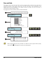
1
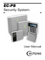
EC-P8
Security System
User Manual
Contents
1. About your Alarm System ......................................................... 4 Introduction ................................................................................................................ 4 About this Manual ...................................................................................................... 4 Fire Detection ............................................................................................................. 4 Monitoring .................................................................................................................. 4 Zones .......................................................................................................................... 5 Access Codes ............................................................................................................. 5 Remote Keypads........................................................................................................ 5 LED Keypad.......................................................................................................... 5 LCD Keypad ......................................................................................................... 6 LED Status Indicators .......................................................................................... 6 Function Keys ...................................................................................................... 7 Emergency Keys .................................................................................................. 7 2. Operating the Alarm System .................................................... 8 Introduction ................................................................................................................ 8 User Menus ................................................................................................................ 8 Before Arming the System ......................................................................................... 9 Away Arm - A ............................................................................................................. 9 Stay Arm 1 - S ......................................................................................................... 10 Stay Arm 2 - 2* ..................................................................................................... 10 Stay Arm 3 - 3* ..................................................................................................... 10 Disarming the System ............................................................................................. 11 Reset after an Alarm ................................................................................................ 11 Bypassing Zones - B ............................................................................................... 12 Walk Test - 11* ................................................................................................... 13 Test Bell & Outputs - 12* .................................................................................... 14 Do Test Call 13* .............................................................................................. 15 View Event Log 21* ......................................................................................... 16 Log Event Codes and Descriptions ......................................................................... 16 Print Event Log 22* ......................................................................................... 20 Call UDL 23* .................................................................................................... 21 Chime on/off 24* ............................................................................................ 22 Change Code 81* ............................................................................................ 23 Program Mode 91* ......................................................................................... 23 View Zone Status 92* ..................................................................................... 24 Exit Menu 99* ................................................................................................. 24 2
P0031-LU-02.01
3. User Programming Menu........................................................ 25 Introduction .............................................................................................................. 25 Text Entry (LCD Only) ............................................................................................... 26 Chime Zones ............................................................................................................ 27 Stay Arm Banner Text .............................................................................................. 28 User Setup................................................................................................................ 29 User Access Code .............................................................................................. 29 User Type ........................................................................................................... 30 User Locked By .................................................................................................. 32 User Name ......................................................................................................... 33 Time and Date.......................................................................................................... 34 4. Fire Safety and System Maintenance ................................... 35 Fire Safety ................................................................................................................ 35 Household Fire Safety Audit .............................................................................. 35 Fire Escape Planning ......................................................................................... 35 Fire Alarm Operation.......................................................................................... 36 System Maintenance ............................................................................................... 36 5. Installation Information ......................................................... 37 Remote Keypads...................................................................................................... 37 Users......................................................................................................................... 37 Zones ........................................................................................................................ 37 Installer Information ................................................................................................ 38 Alarm Receiving Centre Information ....................................................................... 39 P0031-LU-02.01
3
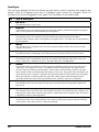
1. About your Alarm System
Introduction
Your alarm system consists of a control panel which is connected to the mains power supply,
one or more remote keypads and various detection devices that are wired back to the
control panel. The control panel will normally be installed out of sight in a utility room or
under stairs cupboard etc. The control panel houses the system’s electronics and stand-by
battery. There is normally no reason for anyone except an installer or service person to have
access to the control panel.
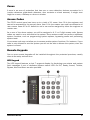
The remote keypad provides the user interface for the system and is used to send
commands to the system and to display the current system status via the various coloured
lights (LED’s) and/or LCD display. The remote keypad also provides audible feedback
annunciation of fault and alarm tones. Each remote keypad should be mounted in
convenient locations inside the protected premises, near to the points of entry and exit.
Please read this manual carefully and have your installer instruct you on your system’s
operation. Become familiar with the features that have been implemented on your system.
All users of this system should be equally instructed in its use.
About this Manual
This manual provides a thorough explanation of all system functions that are available to the
master user, including troubleshooting and programming user access codes in addition to
performing basic system functions. Standard users of the system will not need to know all of
this information. The section “Operating your Alarm System” explains general operating
procedures for arming and disarming the system. The remaining sections of the manual are
reserved for more detailed system information.
Fire Detection
This equipment is capable of monitoring fire detection devices such as smoke detectors and
providing a warning alarm if a fire condition is detected. Good fire detection depends on
having adequate numbers of smoke and heat detectors placed in appropriate locations. This
equipment should be installed in accordance with the relevant local authority fire
regulations. Carefully review the “Fire Escape Planning” guidelines in this manual.
Your installer must enable the fire detection feature before it will work.
Monitoring
This system is capable of transmitting alarms, troubles and emergency information over
telephone lines to an Alarm Receiving Centre (ARC). If you inadvertently initiate an alarm,
immediately call the ARC to prevent an unnecessary response.
Your installer must enable the monitoring function before it will work.
4
P0031-LU-02.01
Zones
A zone is an area of protection that has one or more detection devices connected to it
(motion detectors, glass-break detectors, door contacts or shock sensors). A single zone
might be a room, a hallway or a door or window.
Access Codes
The EC-P8 control panel can have up to a total of 11 users. User 00 is the engineer and
cannot be accessed by the normal users. User 01 is the master user and has access to all
user menus. Users 02 to 11 default to not in use and be assigned by either the engineer or
master user.
As a user of the alarm system, you will be assigned a 4, 5 or 6 digit access code. Access
codes are used to arm and disarm the system. Some access codes can perform additional
system functions, such as programming system options, bypassing zones and performing
system tests.
Your access code may not allow you to access certain system functions. For instance, if your
code is only allowed to arm the system you will not be able to disarm the system, once the
system is armed.
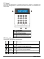
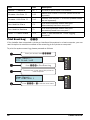
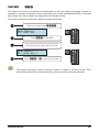
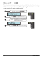
Remote Keypads
One or more remote keypads will be installed throughout the protected premises, usually
close to the entry and exit door.
LED Keypad
The LED keypad features a dual 7 segment display for displaying zone status and system
fault messages. A set of dedicated system status LED’s for AC, Ready, Armed, Trouble,
Bypass, Alert and Alarm are also provided.
P0031-LU-02.01
5
LCD Keypad
The LCD keypad features a 2 x 20 character blue display for showing all zone status and
system fault messages. A set of dedicated system status LED’s for AC, Trouble and Alert are
also provided.
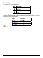
No
Description
Display (LED or LCD)
LED Status Indicators
Number keys, start and hash
Function keys
LED Status Indicators
The LED status indicators are described below:
Icon
6
Name
LED
Description
Power
Green
Mains AC power is present.
Ready
Green
The system is ready for arming.
Armed
Green
The system is armed (Away or Stay).
Fault
Yellow
The system has one or more faults.
Bypass
Yellow
One or more zones are bypassed.
Alert
Red
One or more faults/alarms require attention.
Alarm
Red
One or more alarms have occurred.
P0031-LU-02.01
Function Keys
The function keys are described below:
Key
A
S
B
R
Description
Away Arm
Stay Arm 1
Bypass
Reset
Emergency Keys
The alarm system can provide three immediate emergency alarms by pressing and holding
the following keys for three seconds:
Event
Press Keys
1 and 3
4 and 6
7 and 9
The emergency keys can be individually enabled or disabled for each remote
keypad on your alarm system by the installer.
The Panic alarm (Police) can be individually programmed for either an audible or
silent operation for each remote keypad.
P0031-LU-02.01
7
2. Operating the Alarm System
Introduction
Before attempting to operate the alarm system ensure you have familiarised yourself with all
the procedures covered in this section.
User Menus
Once a valid user access code has been entered at any remote keypad, the user menu is
selected. The table below shows the user menu options and the command numbers used to
access them. All commands with exception to the “Away Arm”, “Stay Arm 1” and “Reset” are
selected by entering their command number followed by *.
Group
Arming
Reset
System Tests
Event Log, UDL &
Chime
Users
Menus
Command
Function
A
S/1
2
3
Away Arm
R
Reset alarm or fault
11
12
13
21
22
23
24
81
Walk Test
91
92
99
Program Mode
Stay Arm 1
Stay Arm 2
Stay Arm 3
Test Bell & Outputs
Do Test Call
View Log
Print Log
Call UDL
Chime on/off
Change code
View Zone Status
Exit Menu
When using the LCD keypad the menu options and their command numbers are
scrolled on the bottom line of the LCD. If the * key is pressed, the menu option
that is currently being displayed is selected.
Only the Master user can access all options in the user menu.
8
P0031-LU-02.01
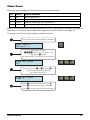
Before Arming the System
Before attempting to arm the system, ensure that all protected areas are secure by closing
any windows etc. If the system is not ready for arming the remote keypads scroll the zones
that are active. The “Ready” indicator on the LED remote keypad will also be off:
Zone 01: Active
Front Door
Zone 04: Active
Lounge Detector
01
04
Ready off
Active zones are scrolled in sequence.
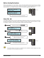
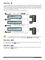
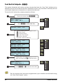
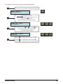
Away Arm - A
The away arming mode is used for protecting all detection zones and is normally used when
leaving the premises unoccupied. Before arming the system check that the system is ready
for arming. To away arm your alarm system, please proceed as follows:
Enter your access code ????.
User Menu
01: Stay Arm 1
Ur
Press the A key.
Exit Now: 010
18:30 28/04/2011
10
The display shows the remaining time
before the system is armed.
System Armed
18:31 28/04/2011
--
Armed on
The system is now away armed.
If the Quick Away Arm feature is enabled at the selected remote keypad, you may
omit step 1 from the above procedure.
P0031-LU-02.01
9
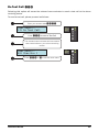
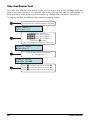
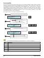
Stay Arm 1 - S
The stay arming mode is used for protecting some of the detection zones and is normally
used when the premises remain occupied. The system has three stay arm modes which
allow the system to be setup for three different protection scenarios. For example “Stay Arm
1” could be configured to provide perimeter protection only, whilst “Stay Arm 2” provides
perimeter and downstairs protection.
To stay arm your alarm system, please proceed as follows:
Enter your access code ????.
User Menu
01: Stay Arm 1
Ur
Press the S key.
Exit Now: 010
18:30 28/04/2011
10
The display shows the remaining time
before the system is armed.
Perimeter Only
18:38 28/04/2011
The system is now stay armed.
--
Armed on
Bypass on
If the Quick Stay Arm feature is enabled at the selected remote keypad, you can
perform a Stay Arm 1, 2 or 3, by simply pressing 1, 2 or 3 followed by S.
Stay Arm 2 - 2*
This option allows you to select the second stay arm mode. Follow the procedure for stay
arm 1 (above), and enter 2* at step 2.
Stay Arm 3 - 3*
This option allows you to select the third stay arm mode. Follow the procedure for stay arm 1
(above), and enter 3* at step 2.
10
P0031-LU-02.01
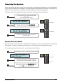
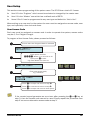
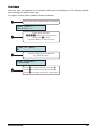
Disarming the System
When the system is away armed, you must enter the protected premises via the designated
entry route (normally the front door). On entering the premises the entry timer and entry tone
starts and you must enter a valid access code before the entry timer expires.
To disarm your alarm system during normal entry, please proceed as follows:
Enter the premises by the designated
entry door.
The entry tone will sound.
An Alarm Company
19:45 28/04/2011
--
Armed on
--
Armed off
Enter your access code ????.
An Alarm Company
19:46 28/04/2011
The entry tone stops and the system is
now disarmed.
Reset after an Alarm
After an alarm has occurred, the display will indicate the source of the alarm on disarming
the system. The alarm indication will remain on the display until the system is reset.
To reset the system after an alarm, please proceed as follows:
Follow steps 1 and 2 for Disarming the System.
Zone 04: Alarmed
Cash Office
The entry tone stops and the system is
now disarmed and indicating an alarm.
04
Armed off
Alarm on
Enter your access code ???? then
press R to reset the alarm.
P0031-LU-02.01
11
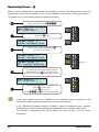
Bypassing Zones - B
When a zone is bypassed it is prevented from causing an alarm. This feature can be used to
temporarily remove the protection of one or more detection zones when arming the system.
To bypass one or more zones, please proceed as follows:
Enter your access code ????.
User Menu:-01: Stay Arm 1
Ur
Press the B key.
Bypass Zone: -Zones Bypassed are:
By
Enter zone number followed by *.
e.g. enter 3* for zone 3.
Bypass Zone: -Zones Bypassed are:
Bypass Zone: -03: Lounge Detector
BY
03
Bypass on
The display scrolls the bypassed zones.
Repeat step 3 to add or remove zones.
When finished press R to exit bypass menu.
User Menu:-01: Stay Arm 1
Ur
The selected zone(s) are now bypassed:
Press A to away arm.
Press S to stay arm.
Enter 99* or R to exit the user menu.
If the Quick Bypass feature is enabled at the selected remote keypad, you may
omit step 1 when bypassing zones from the above procedure.
If the “Reinstate Bypassed Zones on Disarm” option is enabled by your installer,
the selected zones are automatically reinstated when the system is disarmed.
To reinstate a bypassed zone simply select the zone at step 3 in the above
procedure.
12
P0031-LU-02.01
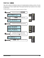
Walk Test - 11*
This option allows the detection zones to be tested without causing an alarm. As each
detector is activated, the keypad generates an acknowledgment tone and the zone number
is recorded on a list of tested zones. The tested zones are then scrolled on the remote
keypad display.
To walk test one or more zones, please proceed as follows:
Enter your access code ????.
User Menu:-11: Do Walk Test
Ur
Enter 11* to select Walk Test
Zones Tested:00
Ct
Activate the zones that require testing
e.g. Activate the detectors for zones 3 & 4.
Zones Tested:03
Lounge Detector
Zones Tested:04
Hallway Detector
The display scrolls the tested zones.
Repeat step 3 to test further zones.
When finished press R to exit the menu.
User Menu:-01: Stay Arm 1
Ct
03
04
Ur
Enter 99* or R to exit the user menu.
P0031-LU-02.01
13
Test Bell & Outputs - 12*
This option allows the bell, strobe and any outputs that have the “User Test” attribute to be
switched on and off so that the devices connected to them may be tested. Normally the bell
and strobe outputs are connected to an external sounder unit.
To test the bell and strobe, please proceed as follows:
Enter your access code ????.
User Menu:-12: Test Bell
Ur
Enter 12* to select Bell Test
Output Test 1-4:
Ot
Use the following keys to toggle output:
1 = Bell Output
2 = Strobe Output
3 = User Test Outputs
4 = Alarm Sounder
e.g. Enter 1234 to select all.
Output Test 1-4:
Bell Active
Output Test 1-4:
Strobe Active
Output Test 1-4:
User Test Active
Output Test 1-4:
User Test Active
Ot
BE
St
UT
AL
Repeat step 3 to toggle outputs on or off.
When finished press R to exit the menu.
User Menu:-01: Stay Arm 1
Ur
Enter 99* or R to exit the user menu.
Only the outputs that have been programmed by your installer are activated during
the “User Test Outputs” option.
14
P0031-LU-02.01
Do Test Call 13*
Selecting this option will cause the onboard communicator to send a test call to the alarm
receiving centre.
To send a test call, please proceed as follows:
Enter your access code ????.
User Menu:-13: Do Test Call
Ur
Enter 13* to send a Test Call
The onboard communicator will now send a
test transmission to your alarm receiving
centre.
User Menu:-01: Stay Arm 1
Ur
Enter 99* or R to exit the user menu.
P0031-LU-02.01
15
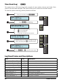
View Event Log
21*
The system has a 250 event log which records all user activity, alarms and faults. Each
event is time and date stamped. This option allows you to review the recorded events.
To view the system event log, please proceed as follows:
Enter your access code ????.
Ur
User Menu:-21: View Log
Enter 21* to View Log.
User 01 Mike
07:35.59 28/04
Use the following keys to:
* = Go backwards
# = Go forwards
e.g. Press *to go back one event.
System Disarmed
07:35.59 28/04
Repeat step 3 to navigate through the log.
When finished press R to exit the menu.
User Menu:-01: Stay Arm 1
UR
01
Sd
07
35
Ur
Enter 99* or R to exit the user menu.
Log Event Codes and Descriptions
LCD
LED
Description
+1/2!"/)/*GG
IA ??
Intruder alarm activated by zone ??.
+1/2!"/"01,/"GG
IR ??
Intruder zone ?? restore.
"/&*"1"/)/*GG
PeA ??
Perimeter alarm activated by zone ??.
"/&*"1"/"01,/"GG
PeR ??
Perimeter zone ?? restore.
:</)/*GG
24HrA ??
24 hour alarm activated by zone ??.
:</"01,/"GG
24HrR ??
24 hour zone ?? restore.
+1/6)/*GG
EA ??
Entry alarm activated by zone ??.
+1/6"01,/"GG
ER ??
Entry zone ?? restore.
16
P0031-LU-02.01
LCD
LED
Description
/+&+$)/*GG
WA ??
Warning alarm activated by zone ??.
/+&+$"01,/"GG
WR ??
Warning zone ?? restore.
"!& ))/*GG
DA ??
Medical alarm activated by zone ??.
"!& )"01,/"GG
DR ??
Medical zone ?? restore.
&/")/*GG
FA ??
Fire alarm activated by zone ??.
&/""01,/"GG
FR ??
Fire zone ?? restore.
)/*GG
PA ??
Panic alarm activated by zone ??.
"01,/"GG
PR ??
Panic alarm zone ?? restore.
&)"+1)/*GG
PSA ??
Silent panic alarm activated by zone ??.
&)"+1"01,/"GG
PSR ??
Silent panic alarm ?? restore.
25)/*GG
AuA ??
Auxiliary alarm activated by zone ??.
25"01,/"GG
AuR ??
Auxiliary zone ?? restore.
,+&1,/)/*GG
MA ??
Monitor alarm activated by zone ??.
,+&1,/"01,/"GG
MR ??
Monitor zone ?? restore.
,+"GG6-00"!
By ??
Zone ?? bypassed.
,+"GG+6-00"!
UBy ??
Zone ?? unbypassed.
*-"/GG)/*
TA ??
Tamper alarm activated by zone ??.
*-"/GG"01,/"
TR ??
Tamper zone ?? restore.
,+"GG2)1)/*
FltA ??
Fault alarm activated by zone ??.
,+"GG2)1"01,/"
FltR ??
Fault on zone ?? has restored.
,+"GG0()/*
MA ??
Mask alarm activated by zone ??.
,+"GG0("01,/"
MR ??
Mask alarm on zone ?? has restored.
,41Y)/*GG
LB ??
Low battery alarm from wireless device on zone ??.
,41Y"01,/"GG
LR ??
Low battery alarm on zone ?? has restored.
6-00 1&3"GG
ByA ??
Group bypass activated by zone ??.
6-00"01,/"GG
ByR ??
Group bypass by zone ?? has restored.
"604&1 % 1&3"GG
SA ??
Keyswitch connected to zone ?? is active.
"604&1 %"01,/"GG
SR ??
Keyswitch connected to zone ?? has restored.
)/* 1&3"
AA
Intruder Alarm is active.
"))0 1&3"
BA
Bell output is active.
"X/*, (,21
RL
Re-arm lockout has occurred and no more alarm can be
generated for the armed period.
,+#&/*"!)/*
CA
Confirmed alarm generated (two different zones
activated).
"*,1"
RA ??
Remote access via PC number ??.
Ur ??
User access by user ??.
"00GG
0"/GG
P0031-LU-02.01
17
LCD
LED
Description
2/"00GG
Dr ??
Duress alarm by user ??.
0"/$GG
UT ??
User ?? proximity tag access.
0"/GG, (,21
UL ??
User ?? has been locked out from using the system.
0"/$GG, (,21
TL ??
User ?? proximity tag has been locked out from using
the system.
,!"*-"/G
CT ?
Code tamper (invalid code) generated at keypad ?.
5&11/1"!GG
ESU ??
Exit mode started by user ??.
5&11/1"!&*"/G
EST ??
Exit mode started by control timer ?.
5&11/1"!,+"GG
ESC ??
Exit mode started by zone ??.
5&11,--"!
ES
Exit mode stopped.
5&1&)"!QGG
EF ??
Exit mode failed by zone ??.
+1/61/1"!GG
EN ??
Entry mode stared by zone ??.
+1/6&*",21
ET
Entry timeout alarm.
601"*/*"!
SA
System armed.
601"*&0/*"!
SD
System disarmed.
16/*"!QG
S ?
Stay armed #? (? = 1, 2 or 3).
/*&)"!QG
AF ?
Arming failed.
/*"!&1%2)1
AU
The system was armed with an Alarm Transmission
System (ATS) fault.
21,/*"!
AA
The system was automatically armed.
21,&0/*"!
AD
The system was automatically disarmed.
"*,1"/*"!
RA
The system was automatically armed remotely.
"*,1"&0/*"!
RD
The system was automatically disarmed remotely.
601"*,4"/-
SU
The system was powered up.
&)"!
ACOff
The mains ac supply has been switched off.
"01,/"
ACOn
The mains ac supply has been restored.
11"/62)1QG
BF
Battery fault #? (1: Presence Fail; 2: Load Test Fail).
11"/6"01,/"
BR
Battery fault restored.
,411"/6)/*
LB
The system standby battery voltage is low (The system
is running on battery only).
&*"Z1"%+$"!
TD
The system time and date has been changed.
+$&+""/,+0&1"
ENON
The engineer access code has been entered.
+$&+""/,##0&1"
ENOF
The engineer has logged off.
"))20")/*
BFAL
The bell fuse has gone open circuit (electronic fuse).
"))20""01,/"
BFAR
The bell fuse has restored.
2520")/*
AFAL
The auxiliary 12V fuse has gone open circuit (electronic
18
P0031-LU-02.01
LCD
LED
Description
fuse).
2520""01,/"
AFAR
The auxiliary 12V fuse has restored.
11"/620")/*
BFAL ?
The battery fuse has gone open circuit (electronic fuse).
11"/620""01,/"
BFAR
The battery fuse has restored.
,5*-"/)/*
BTAL
The control panel box tamper has been activated.
,5*-"/"01,/"
BTAR
The control panel box tamper has restored.
"6-!G*-"/
RTAL ?
Keypad ? box tamper has been activated.
"6-!G*-"01
RTAR ?
Keypad ? box tamper has restored.
"3& "GG,01
RL ?
Device ?? on network lost.
"3& "GG,2+!
RF ?
Device ?? on network found.
)(1"011/1"!
TS
User walk test mode started.
)(1"01+!"!
TE
User walk test mode ended.
"))"011/1"!
BTS
User bell test started.
"))"01+!"!
BTE
User bell test ended.
21,"01))
ATC
An automatic test call was sent to the Alarm Receiving
Centre (ARC).
+2)"01))
TC
A manual (user) test call was sent to the Alarm
Receiving Centre (ARC).
&*"/G+
CT ? ON
Control Timer ? is on.
&*"/G##
CT ? OFF
Control Timer ? is off.
,+""01GG60
TS ??
Zone soak test has started and will run for ?? days.
,+"GG"01&)
TF ??
Zone ?? has failed whilst on test.
&/01+, (GG
FN ??
First activation from zone ??. The zone has the “Double
Knock” attribute.
)/*,/1"!
AA
The user has disarmed the system within the abort
delay period.
"))*-"/)/*
BTAL
The bell tamper alarm has been activated.
"))*-"/"01,/"
BTAR
The bell tamper has restored.
2)1
ATSF
The Alarm Transmission System (ATS) has detected a
fault with the telephone line.
"01,/"!
ATSR
The ATS Fault has restored.
"6-!G
RP ? A
A panic alarm was generated at keypad ? by pressing
keys 7 and 9.
"6-!&/"G
RF ? A
A fire alarm was generated at keypad ? by pressing keys
1 and 3.
"6-!"!& )G
RD ? A
A medical alarm was generated at keypad ? by pressing
keys 4 and 6.
21-21G2)1
OPF ?
The system has detected a fault on panel output ?.
P0031-LU-02.01
19
LCD
LED
Description
21-21G"01,/"
OPR ?
The fault on panel output ? has restored.
)"+"/+X&1"GG
CLOS
Cleaner user number ?? is on-site (Cleaner zones are
bypassed).
)"+"/##X&1"GG
CLoS
Cleaner user number ?? is off-site (Cleaner zones
are un-bypassed).
,*,!2)")/*
C?A
The communication module has been
disconnected/lost from com port ?
,*,!2)""01,/"
C?R
The communication module has been
connected/found from com port ?
,+"GG,2+1)/*
??CA
Zone ?? has reached the “Count Logging”
threshold.
Print Event Log
22*
If the installer has connected a printer or interfaced the system to a host computer, you can
use this option to send the contents of the event log to the printer or computer.
To print the system event log, please proceed as follows:
Enter your access code ????.
User Menu:-22: Print Log
Ur
Enter 22* to Print Event Log
The event log is now sent to the printer or
host computer.
User Menu:-01: Stay Arm 1
Ur
Enter 99* or R to exit the user menu.
20
P0031-LU-02.01
Call UDL
23*
This option will cause the onboard communicator to dial the remote computer modem to
establish a remote connection. Once connected, the remote up/download (UDL) computer
can access your alarm system for diagnostics and programming.
To call the remote UDL computer, please proceed as follows:
Enter your access code ????.
User Menu:-23: Call UDL
Ur
Enter 23* to Call UDL
The onboard communicator will attempt to
connect with the remote UDL computer.
User Menu:-01: Stay Arm 1
Ur
Enter 99* or R to exit the user menu.
The remote computer must be setup so that it is ready to receive the call. Only
select this option when instructed to do so by the remote computer operator.
P0031-LU-02.01
21
Chime on/off
24*
This option allows the chime feature to be turned on and off. If the chime feature is on then
any zone that is activated will cause the system to generate a chime response according to
how the zone is programmed, see page 27 for programming “Zone Chime”.
To turn chime on or off, please proceed as follows:
Enter your access code ????.
User Menu:-24: Chime on/off
Ur
Enter 24* to toggle chime on or off
A chime tone indicates that chime has been
turn on. An acceptance tone indicates that
chime has been turn off.
User Menu:-01: Stay Arm 1
Ur
Enter 99* or R to exit the user menu.
22
P0031-LU-02.01
Change Code
81*
This option allows you to change your own access code. Your access code can be 4, 5 or 6
digits in length.
To change your own access coder, please proceed as follows:
Enter your access code ????.
User Menu:-81: Change Code
Ur
Enter 81* to Change Code.
Enter New Code:
ÿ
81
Enter new code 4, 5 or 6 digits, then press *.
User Menu:-01: Stay Arm 1
Ur
Enter 99* or R to exit the user menu.
If the remote keypad generates an error tone after pressing the * key at step 3,
then the access code cannot be used. Simply repeat the procedure from step 2 but
use an alternative access code at step 3.
Program Mode
91*
This option selects the user programming mode. This option is only available to the master
user. Please refer to the next section for full details on user programming options.
P0031-LU-02.01
23
View Zone Status 92*
This option selects allows you view the real time status and activity count of each detection
zone. The table below shows the possible status for a zone:
Status
Description
Healthy
Detector is healthy
Active
Detector is active, e.g., door open or movement detected
Tamper
Detector cover has been removed or cable has been cut
Shorted
Cable to detector is short circuit
Not Fitted
The zone not in available
Enter your access code ????.
User Menu:-01: Stay Arm
Ur
Enter 92* to View Zone Status
Zone 01 Healthy
Front Door
01 =H
Press # to view next zone.
Press * to view previous zone.
Press A to toggle status/count.
Press 1 - 8 to select the zone.
e.g., press 5 to select zone 5.
Zone 05 Active
Office PIR Detector
05 =A
Press R to exit the View Zone
Status mode.
User Menu:-01: Stay Arm
Ur
Enter 99* or press R twice to exit
the user menu.
Exit Menu
99*
This option exits the user or programming menus and returns the system to the normal
disarmed state.
24
P0031-LU-02.01
3. User Programming Menu
Introduction
The master user has access to the user programming menu. The user programming menu is
used to access the more advance features of your system. The table below shows the menu
options that are available:
No
Option
Page
1601 to 1618
Zone 01 to 18 Chime Options
27
3601 to 3603
Stay Arm 1 to 3 Banner Text
27
8101 to 8110
Users 01 to 10 Access Code
29
8201 to 8210
Users 01 to 10 User Type
30
8301 to 8310
Users 01 to 10 User Locked By
32
8401 to 8410
Users 01 to 10 User Name
33
9001 to 9006
Time & Date (Hours, Mins, Secs, Day, Month & Year)
34
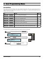
To access the user programming menu, please proceed as follows:
Enter the master access code ????.
User Menu:-91: Program Mode
Ur
Enter 91* to select User Programming
User Menu:-Option:----
Ur
Enter a four digit menu option
????.
P0031-LU-02.01
25
Text Entry (LCD Only)
Some programming options such as user names and banner text require text to be entered.
These options should be selected when using the LCD remote keypad. The text is entered in
the same way as entering text on a mobile telephone. Each key is mapped to one or more
letters. Pressing a key will select the first letter, pressing it again will select the next etc. The
table below shows the keys to use and the characters that are assigned to them:
Key
Characters
1
2
3
4
5
6
7
8
9
1
0
B
26
A
B
C
2
A
b
c
D
E
F
3
D
e
F
G
H
I
4
G
h
i
J
K
L
5
J
k
l
M
N
O
6
M
n
o
P
Q
R
S
7
p
q
T
U
V
8
T
u
v
W
X
Y
Z
9
w
x
_
0
.
-
(
)
#
r
s
y
z
Clear all characters
P0031-LU-02.01
Chime Zones
Each zone can be assigned a chime option from the table below:
No
Option
System Response
0
Off
No tone generated.
1
Tone 1
A single “Bing-Bong” tone is generated.
2
Tone 2
A double “Bing-Bong” tone is generated.
3
Tone 3
A triple “Bing-Bong” tone is generated.
When the zone is activated during the disarmed mode, it generates a response according to
table above. The Chime feature can also be globally turned on and off, see page 22.
To program the Chime Zones, please proceed as follows:
Ensure that User Program Mode is selected.
User Menu:-Option:----
Ur
Enter option number:
16??: Where ?? is zone 01 to 18
Then press * to edit.
e.g. Enter 1605* for Zone 05 Chime options.
Zone 05 Chime
Off
16 05 =0
Enter new option 0 to 3 or press B to
scroll through options (LCD Only),
e.g, Press 1 for Tone 1.
Zone 05 Chime
Tone 1
Press * to accept and return to step Ì.
Press R to cancel and return to step Ë.
Press # to accept and move to next option.
P0031-LU-02.01
16 05 =5
...
27
Stay Arm Banner Text
The “Stay Arm Banners” are shown on the top line of the LCD remote keypads when the
system has been armed in the relevant stay mode. The banners can be personalised to
show text that is more relevant to your system, e.g. “Garage Only” instead of “Stay Arm 2”.
To program the Stay Arm Banner Text, please proceed as follows:
Ensure that User Program Mode is selected.
User Menu:-Option:---Enter option number:
3601: Stay Arm 1 Banner
3602: Stay Arm 2 Banner
3603: Stay Arm 3 Banner
Then press * to edit.
e.g. Enter 3602* for Stay Arm 2 Banner.
Stay 2 Text:
ÿtay Arm 2
Use text editing keys to enter text,
e.g, “Garage Only”.
Stay 2 Text:
Garage Onlyÿ
Press * to accept and return to step Ì.
Press R to cancel and return to step Ë.
Press # to accept and move to next option.
28
P0031-LU-02.01
User Setup
This section covers programming of the system users. The EC-P8 has a total of 11 users:
f
User 00 is the “Engineer” which cannot be selected or changed by the master user.
f
User 01 is the “Master” user which has a default code of 5678.
f
Users 02 to 10 can be programmed to any user type and default to “Not in Use”.
When setting up a new user for the system the user must be assigned an access code, user
type, and optionally a time lock and name.
User Access Code
Each user must be assigned an access code in order to operate the system; access codes
may be 4, 5 or 6 digits in length.
To program a User Access Code, please proceed as follows:
Ensure that User Program Mode is selected.
User Menu:-Option:----
Ur
Enter option number:
81??: Where ?? is user 01 to 10
Then press * to edit.
e.g. Enter 8102* for User 02.
User 02 Code:
ÿ
81 02 =
Enter new access code,
e.g, “020202”.
User 02 Code:
020202ÿ
Press * to accept and return to step Ì.
Press R to cancel and return to step Ë.
Press # to accept and move to next option.
81 02 =0 20
...
If the remote keypad generates an error tone after pressing the * or # key at
step 3, then the access code cannot be used. Simply repeat the procedure from
step 2 but use an alternative access code at step 3.
P0031-LU-02.01
29
User Type
The user type defines the level of access the user has in order to operate and program the
system. User 00 (Engineer) and User 01 (Master) types cannot be changed. Users 02
through to 10 can be assigned to user types 3 to 9 as shown in the table below:
No
Type & Description
0
Not in Use
The selected user is not in use.
1
Engineer
The selected user is an engineer and can access all options within the engineer’s program
menu. This type can only be selected by the engineer.
2
Technician
The selected user is a Technician and can access all options except the onboard
communication options within the engineer’s program menu. This type can only be selected
by the engineer.
3
Master
The selected user is a Master user and can access all options within the user menu and
program new users.
4
Manager
The selected user is a Manager user and can access all options within the user menu.
5
Standard
The selected user is a Standard user and can access the following options from the user
menu: “Away Arm”, “Stay Arm 1/2/3”, “Do walk Test” and “Change Code”.
6
Cleaner
The selected user is a Cleaner and can access the following options from the user menu:
“Away Arm” and “Stay Arm 1/2/3”. The cleaner code can only disarm the system if the
cleaner code was used to arm the system. If the system was armed by another user type
and a cleaner code is entered whilst the system is armed or during the entry procedure, the
zones that have the “Cleaner” attribute are bypassed and the entry procedure is cancelled.
When the cleaner is ready to leave the premises, entering their code will start the exit
procedure and at the end of the exit procedure the “Cleaner” zones are reinstated.
7
Arm Only
The selected user is an Arm Only user and can only access the arming options within the
user menu
8
Duress
The selected user is a Duress user and operates the same as a standard user, however, on
entering the access code a silent duress alarm is generated and if programmed, the event
is signalled to alarm receiving centre.
9
Access Control
The selected user is an Access Control user and on entering the access code the relevant
“User Access” and “Door Access” output is activated.
30
P0031-LU-02.01
To program a User Type, please proceed as follows:
Ensure that User Program Mode is selected.
User Menu:-Option:----
Ur
Enter option number:
82??: Where ?? is user 01 to 10
Then press * to edit.
e.g. Enter 8202* for User 02 Type.
User 02 Type:
Standard
82 02 =5
Enter new type 3 to 9 or press B to
scroll through options (LCD Only),
e.g, Press 4 for Manager.
User 02 Type:
Manager
Press * to accept and return to step Ì.
Press R to cancel and return to step Ë.
Press # to accept and move to next option.
P0031-LU-02.01
82 02 =4
...
31
User Locked By
The user access can be locked out by the use of a “Link Controlled” output. This is a special
software controlled output that is configured by your installer. The “Link Control” output can
be configured to switch on by various link input conditions, e.g., “Link Control 01” could be
programmed to operate when Control Timer 2 is active. This means that the user access
code is disabled when the selected “Link Control” output is on and can be used for locking
out selected users for particular conditions, e.g. you may want to prevent a user from
accessing the system over the weekend.
To program a User Lock, please proceed as follows:
Ensure that User Program Mode is selected.
User Menu:-Option:----
Ur
Enter option number:
83??: Where ?? is user 01 to 10
Then press * to edit.
e.g. Enter 8302* for User 02 Lock.
User 02 Locked By:
000
83 02 =0
Enter Link Control number,
e.g, Enter 01 to lock user by Link Control 01.
User 02 Locked By:
001
83 02 =1
Press * to accept and return to step Ì.
Press R to cancel and return to step Ë.
Press # to accept and move to next option.
Your installer will configure the actual function for each Link Control.
Link
32
Function
P0031-LU-02.01
User Name
Each user can be assigned an 8 character label that is displayed on LCD remote keypads
when viewing the system event log.
To program a User Name, please proceed as follows:
Ensure that User Program Mode is selected.
User Menu:-Option:---Enter option number:
84??: Where ?? is user 01 to 10
Then press * to edit.
e.g. Enter 8402* for User 02 Type.
User 02 Name:
ÿ
Use text editing keys to enter text,
e.g, “Michael” Only”.
User 02 Name:
Michaelÿ
Press * to accept and return to step Ì.
Press R to cancel and return to step Ë.
Press # to accept and move to next option.
P0031-LU-02.01
33
Time and Date
The system has a real time clock that must be programmed so that the time and date is
recorded correctly in the system event log. The time and date is also displayed on the
bottom line of the LCD keypad. If the system looses all power, the time and date is
maintained for approximately 2 days.
To program the Time and Date, please proceed as follows:
Ensure that User Program Mode is selected.
User Menu:-Option:----
Ur
Enter option number:
9001: Hours
9002: Minutes
9003: Seconds
9004: Day
9005: Month
9006: Year
Then press * to edit.
e.g. Enter 9001* for Hours.
Set Hours
90 01 =2 3
23
Enter new value,
e.g, Enter 17for 5pm .
Set Hours
17
Press * to accept and return to step Ì.
Press R to cancel and return to step Ë.
Press # to accept and move to next option.
90 01 =1 7
...
When programming the time and date it is easier to start at option 9001 (hours),
then use the # key at step 4 to move to the next option.
34
P0031-LU-02.01
4. Fire Safety and System Maintenance
Fire Safety
Household Fire Safety Audit
Most fires occur in the home. To minimise the risk of fire, it is recommended that a
household safety audit is conducted and a fire escape plan is developed.
f
Are all electrical appliances and outlets in a safe condition? Check for frayed power
leads, overloaded lighting circuits, etc. If you are uncertain about the condition of your
electrical appliances or household service, have a professional evaluate these units.
f
Are all flammable liquids stored safely in closed containers in a well ventilated cool
area? Cleaning with flammable liquids should be avoided.
f
Are fire hazardous materials (matches and lighters) well out of reach of children?
f
Are heating boilers and wood burning appliances properly installed, clean and in good
working order? Have a professional evaluate these appliances.
Fire Escape Planning
There is often very little time between the detection of a fire and the time it becomes deadly.
It is therefore very important that a family escape plan be developed and rehearsed.
Every family member should participate in developing the escape plan.
Study the possible escape routes from each location within the house. Since many fires
occur at night, special attention should be given to the escape routes from sleeping
quarters.
Escape from a bedroom must be possible without opening the interior door. Consider the
following when making your escape plans:
f
Make sure that all perimeter doors and windows are easily opened. Ensure that they
are not painted shut and that their locking mechanisms operate smoothly.
f
If opening or using the exit is too difficult for children, the elderly or handicapped, plans
for rescue should be developed. This includes making sure that those who are to
perform the rescue can promptly hear the fire warning signal.
f
If the exit is above the ground level, an approved fire ladder or rope should be provided
as well as training in its use.
f
Exits on the ground level should be kept clear. Be sure to remove snow from exterior
patio doors in winter; outdoor furniture or equipment should not block exits.
f
Each person should know of a predetermined assembly point where everyone can be
accounted for i.e. across the street or at a neighbour's house. Once everyone is out of
the building, call the Fire Services.
f
A good plan emphasises quick escape. Do not investigate or attempt to fight the fire,
and do not gather belongings or pets as this wastes valuable time. Once outside, do
not re-enter the house. Wait for the Fire Services.
P0031-LU-02.01
35
f
Write the fire escape plan down and rehearse it frequently so that should an
emergency arise, everyone will know what to do. Revise the plan as conditions change,
such as the number of people in the home, or if there are changes to the building's
construction.
f
Make sure your fire warning system is operational by conducting weekly tests. If you
are unsure about system operation, contact your installer.
f
We recommend that you contact your local fire department and request further
information on fire safety and escape planning. If available, have your local fire
prevention officer conduct an in-house fire safety inspection.
Fire Alarm Operation
When a fire alarm is detected, the system generates a distinctive fire alarm tone from the
remote keypads and the external bell or siren is also pulsed on and off. The alarm is also
transmitted to the Alarm Receiving Centre, if your installer has enabled this feature.
To silence the fire alarm condition, simply enter your access code.
Resetting Smoke Detectors
When a smoke detector is triggered it will normally remain in a latched alarm condition until
it has been reset. If after a reset, it still detects smoke, the alarm sequence will sound as
described above. If there is no smoke, the system will return to normal operation.
To reset smoke detectors, enter your access code then press the R key.
If you suspect that a fire alarm has been transmitted and that there is no fire
condition, call the alarm receiving centre to avoid an unnecessary response. If a
fire condition is apparent, follow your evacuation plan immediately.
System Maintenance
With normal use, the system requires little maintenance, other than that required by local
regulations. The following points should be observed.
f
Do not wash the security control panel, keypads and detectors with a wet cloth. A light
dusting with a slightly moistened cloth should remove normal accumulations of dust.
f
The control panel stand-by battery test is designed to determine the battery condition.
We recommend, however, that the stand-by batteries are replaced every five years.
f
For other system devices such as smoke detectors, passive infrared, ultrasonic or
microwave motion detectors or glass-break detectors, consult the respective
manufacturer’s literature for testing and maintenance.
36
P0031-LU-02.01
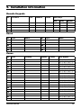
5. Installation Information
Remote Keypads
No
Location
Fire
Medical
Police
Quick Keys
Arm
Stay
Bypass
1
2
3
4
Users
No
Type
01
Master
Name
No
Type
Name
06
02
07
03
08
04
09
05
10
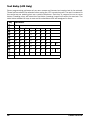
Zones
No
Type
01
02
03
04
05
06
07
08
09
10
11
12
13
14
15
16
17
18
P0031-LU-02.01
Location
Bypass
Chime
Stay Bypass
1[ ] 2[ ] 3[
1[ ] 2[ ] 3[
1[ ] 2[ ] 3[
1[ ] 2[ ] 3[
1[ ] 2[ ] 3[
1[ ] 2[ ] 3[
1[ ] 2[ ] 3[
1[ ] 2[ ] 3[
1[ ] 2[ ] 3[
1[ ] 2[ ] 3[
1[ ] 2[ ] 3[
1[ ] 2[ ] 3[
1[ ] 2[ ] 3[
1[ ] 2[ ] 3[
1[ ] 2[ ] 3[
1[ ] 2[ ] 3[
1[ ] 2[ ] 3[
1[ ] 2[ ] 3[
]
]
]
]
]
]
]
]
]
]
]
]
]
]
]
]
]
]
37
Installer Information
Installation Company:
Address:
Telephone (Normal):
Telephone (Emergency):
Email:
Web Site:
Notes
38
P0031-LU-02.01
Alarm Receiving Centre Information
Company:
Address:
Account Number:
Telephone (Normal):
Telephone (Emergency):
Email:
Web Site:
Notes
P0031-LU-02.01
39