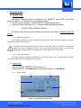
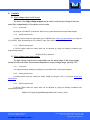
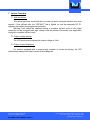
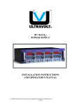
1
User’s Manual MAKING HIGH VOLTAGE EASIER!® BT SERIES AC-DC high voltage, low power, bench-top power supply Rev. A 5/2011 This manual is specifically intended for specialists trained in the use of high voltage equipment and aware of the dangers inherent in its use. S.C.P.I. Compliant. This device fully complies with S.C.P.I. version 1999.0. Visit us online: www.ultravolt.com Contact us: [email protected] 1800 Ocean Avenue, Ronkonkoma, NY 11779 - USA Tel :1-631-471-4444 Fax : 1-631-471-4696 Copyright ©2011 UltraVolt, Inc. Contact Us UltraVolt, Inc. 1800 Ocean Avenue Ronkonkoma, NY 11779 USA T : +1 (631) 471-4444 F : +1 (631) 471-4696 [email protected] www.ultravolt.com Visit us online: www.ultravolt.com Contact us: [email protected] BT SERIES USER’S MANUAL PAGE 2 1800 Ocean Avenue, Ronkonkoma, NY 11779 - USA Tel :1-631-471-4444 Fax : 1-631-471-4696 Copyright ©2010 UltraVolt, Inc. Contents 1. OVERVIEW...................................................................................................................4 2. SAFETY INFORMATION..............................................................................................5 3. TECHNICAL DATA.......................................................................................................7 3.1. TECHNICAL SPECIFICATIONS ............................................................................................7 3.2. CONNECTORS SPECIFICATIONS........................................................................................9 3.2.1. Digital RS-232 SUBD9 specifications....................................................................9 3.2.2. Analog remote specifications ..............................................................................10 4. GETTING STARTED ..................................................................................................11 4.1. WARRANTIED CHARACTERISTICS/SPECIFICATIONS ...........................................................11 4.2. UNPACKING AND INSPECTING THE INSTRUMENT ...............................................................11 4.3. FRONT PANEL CONTROLS AND INDICATORS .....................................................................12 4.4. REAR PANEL ................................................................................................................13 4.5. MECHANICAL SETTINGS ................................................................................................13 4.6. ELECTRICAL SETTINGS .................................................................................................14 5. OPERATING MODES.................................................................................................15 5.1. REMOTE MODE .............................................................................................................15 5.1.1. RS-232 remote mode ..........................................................................................15 5.1.2. Analog remote mode...........................................................................................15 5.2. LOCAL MODE................................................................................................................15 5.2.1. Screen display.....................................................................................................15 5.2.2. Navigation menu .................................................................................................16 6. CONTROLS ...............................................................................................................17 6.1. HIGH VOLTAGE OUTPUT ON/OFF CONTROL ......................................................................17 6.1.1. Local mode..........................................................................................................17 6.1.2. Analog remote mode...........................................................................................17 6.1.3. RS-232 remote mode ..........................................................................................17 6.2. HIGH VOLTAGE OUTPUT LEVEL CONTROL ........................................................................17 6.2.1. Local mode..........................................................................................................17 6.2.2. Analog remote mode...........................................................................................17 6.2.3. RS-232 remote mode ..........................................................................................17 7. VARIOUS FUNCTIONS ..............................................................................................18 7.1. SELF-TEST FAILURE ......................................................................................................18 7.2. OUTPUT VOLTAGE DISPLAY ...........................................................................................18 7.3. OUTPUT CURRENT DISPLAYING ......................................................................................18 8. MAINTENANCE AND SERVICE ................................................................................19 9. PROTECTION.............................................................................................................20 10. STANDARDS..............................................................................................................20 11. PRODUCT LABEL......................................................................................................20 12. WARRANTY ...............................................................................................................21 Visit us online: www.ultravolt.com Contact us: [email protected] BT SERIES USER’S MANUAL PAGE 2 1800 Ocean Avenue, Ronkonkoma, NY 11779 - USA Tel :1-631-471-4444 Fax : 1-631-471-4696 Copyright ©2010 UltraVolt, Inc. 1. Overview This product is a compact high voltage AC-DC bench-top power supply with adjustable output voltage and fixed current limiting. The device allows both local and remote operations. For stand-alone operation, the power supply is fitted with integrated push buttons for local manual programming. For remote operation, it is fitted either with an analog control port (by default) or with a serial interface supporting a RS232 port (optional). For the optional RS232 version, the ordering code of the device must include the suffix “-RS”. The BT features: • • • • • a large 128x64 graphical LCD backlighted display voltage control functions one SHV or BNC high voltage coaxial connector an analog remote control port (by default) or an optional SCPI compliant RS-232 communication port (replaces the analog port) All instrument features are available via the communication ports. Visit us online: www.ultravolt.com Contact us: [email protected] BT SERIES USER’S MANUAL PAGE 2 1800 Ocean Avenue, Ronkonkoma, NY 11779 - USA Tel :1-631-471-4444 Fax : 1-631-471-4696 Copyright ©2010 UltraVolt, Inc. 2. Safety Information This power supply is specifically intended for specialists qualified in the use of high voltage equipment and aware of the dangers inherent in its use. Review this safety information carefully to avoid injury and prevent damage to the power supply or any equipment connected to it. There are no user serviceable parts inside this power supply. Prior to operation, thoroughly review all safety, installation, and operating instructions accompanying this equipment. All instructions must be followed. Power Source: • Use only the power cord specified for this device. The grounding conductor of the cord must be connected to earth ground. Environment: • Do not operate this power supply in wet or damp conditions or in an explosive atmosphere. • This device is designed to work in an ambient of temperature of 0/+40°C. Do not expose to direct sunlight for an extended period of time. The Instrument: • • • DO NOT OPEN THIS POWER SUPPLY. Opening the device is dangerous to the user and will void any and all warrantees. Do not operate it if its panels are removed or any of the interior circuitry is exposed. Do not apply a voltage outside the specified range to any of the terminals. Warning: Do not attempt modification, maintenance or repair to this device. All servicing on this equipment must be carried out by UltraVolt service personnel only. Visit us online: www.ultravolt.com Contact us: [email protected] BT SERIES USER’S MANUAL PAGE 5 1800 Ocean Avenue, Ronkonkoma, NY 11779 - USA Tel :1-631-471-4444 Fax : 1-631-471-4696 Copyright ©2011 UltraVolt, Inc. Warning symbols: Attention symbol: Indicates important installation, operating, and/or maintenance instructions. Shock Hazard symbol: Indicates risk of electric shock. Visit us online: www.ultravolt.com Contact us: [email protected] BT SERIES USER’S MANUAL PAGE 6 1800 Ocean Avenue, Ronkonkoma, NY 11779 - USA Tel :1-631-471-4444 Fax : 1-631-471-4696 Copyright ©2011 UltraVolt, Inc. 3. Technical Data 3.1. Technical specifications Parameters Specifications Input voltage Vin universal 85-264 VAC Mains ON/OFF controls switch on rear panel Output voltage Vout from 0-100V through 0-6000V Output power Pout from 0.1W to 6W depending on model Polarity positive or negative depending on model Load voltage regulation ± 0.01% of full output voltage for no load to full load - typically Line voltage regulation ± 0.01% of full output voltage over specified input voltage range - typically Residual ripple < 0.05% typically Temperature coefficient 100ppm/°C (higher stability upon request) Safeguards banana plug for grounding on rear panel Remote mode specifications Local mode specifications digital version Local / remote mode RS 232 or field bus front panel controls High Voltage ON/OFF analog version analog signals, SUBD9 connector on rear panel Voltage setting Remote mode monitoring Local mode monitoring digital version Output voltage monitoring LCD display on front panel Output current monitoring (only available with some models – refer to Selection Guide) RS 232 or field bus analog version analog signals, SUBD9 connector on rear panel Mechanical configuration Insulation high voltage assembly fully potted Case high quality ABS material Dimensions 7.83 in (199.0 mm)L x 6.2 in (157.5 mm)W x 2.45 in (62.2 mm)H Mains input IEC 320 type AC connector fuse (L 500mA) on rear panel High voltage connector secured SHV connector on rear panel Accessories to order separately SHV cable URM70 – length to order For further electrical specifications, please refer to the corresponding datasheet of each type of HV converter used in the BT box (available online at www.ultravolt.com). Visit us online: www.ultravolt.com Contact us: [email protected] BT SERIES USER’S MANUAL PAGE 7 1800 Ocean Avenue, Ronkonkoma, NY 11779 - USA Tel :1-631-471-4444 Fax : 1-631-471-4696 Copyright ©2011 UltraVolt, Inc. Mechanical Dimensions Front view Back view Side view Visit us online: www.ultravolt.com Contact us: [email protected] BT SERIES USER’S MANUAL PAGE 8 1800 Ocean Avenue, Ronkonkoma, NY 11779 - USA Tel :1-631-471-4444 Fax : 1-631-471-4696 Copyright ©2011 UltraVolt, Inc. 3.2. Connectors specifications 3.2.1. Digital RS-232 SUBD9 specifications This connector partially complies with the EIA232 Data Communication Equipment (DTE) standard. The implemented signals are : • the data exchange lines RX and TX • and the flow control lines RTS (Request To Send) and CTS (Clear To Send). Figure 1 : RS-232 SUBD9 according to standard EIA232. #Pin Name 1 2 3 4 5 6 7 8 9 SH Type NC TX RX NC GND NC CTS RTS NC Shield Notes Transmit data Receive data Ground Clear to send Request to send Shielding From the start the default communication protocol is at a speed of 57600 baud, 8 bits data with no parity bit and 1 stop bit. The flow control is activated (Ready For Receiving Mode). You can change the serial port speed with the following commands: SYSTem:COMMunicate:SERial:TRANsmit:BAUD <numeric_value> or SYSTem:COMMunicate:SERial[:RECeive]:BAUD <numeric_value> with <numeric_value> in the range from 9600 to 115200. You can change flow control mode with the following command: SYSTem:COMMunicate:SERial:CONTrol:RTS ON|OFF|RFR See programming manual for details. Visit us online: www.ultravolt.com Contact us: [email protected] BT SERIES USER’S MANUAL PAGE 9 1800 Ocean Avenue, Ronkonkoma, NY 11779 - USA Tel :1-631-471-4444 Fax : 1-631-471-4696 Copyright ©2011 UltraVolt, Inc. 3.2.2. Analog remote specifications All the inputs of this connector are high impedance TTL input except the external analog command with an impedance of 100KOhm. Figure 2 : Remote SUBD9 #Pin Name 1 2 3 4 5 6 7 8 9 SH D_GND HV_ON/OFF HVM_C HVM_V REF LOCAL/REMOTE NC A_GND HVC_V Shield Type Notes TTL Buffered Buffered Buffered TTL Digital ground * Inhibit input Output current monitoring Output voltage monitoring Reference output If LOCAL/REMOTE is high, device is in analog remote control mode 100kOhms Analog ground * Voltage control input Shielding *Analog and digital grounds are internally connected. Visit us online: www.ultravolt.com Contact us: [email protected] BT SERIES USER’S MANUAL PAGE 10 1800 Ocean Avenue, Ronkonkoma, NY 11779 - USA Tel :1-631-471-4444 Fax : 1-631-471-4696 Copyright ©2011 UltraVolt, Inc. 4. Getting started This device is delivered with the current user’s guide, an electric power cord and on demand with one or more high voltage coaxial cable(s) with connectors. Please, read carefully before installing or operating this product. 4.1. Warrantied characteristics/specifications • • • • The equipment described in this manual is to be operated indoors only. The equipment described in this manual can be operated independently of its position (vertical, horizontal, etc). Ambient Temperatures o Operating 0°C to +40°C (32°F to +104°F) o Storage -20°C to +70°C (-4°F to +158°F) Relative Humidity o 0 to 95% at or below +30°C (+86°F) o 0 to 75% from +31°C to +40°C (+87°F to +104°F) 4.2. Unpacking and inspecting the instrument The equipment described in this manual was delivered to the carrier in good condition and properly packaged. Immediately open all boxes comprising this shipment and inspect the instruments for lost or damaged parts, including case damage, proper button function, etc. In the unlikely event of damage: 1. Save all shipping boxes and cartons for inspection by the carrier until the claim is settled. 2. Notify the carrier or transfer agent immediately for a prompt inspection of the claimed loss or damage. 3. File the claim with the carrier. 4. If necessary, order replacement parts from ULTRAVOLT and collect the invoice amount from the carrier. Visit us online: www.ultravolt.com Contact us: [email protected] BT SERIES USER’S MANUAL PAGE 11 1800 Ocean Avenue, Ronkonkoma, NY 11779 - USA Tel :1-631-471-4444 Fax : 1-631-471-4696 Copyright ©2011 UltraVolt, Inc. 4.3. Front panel controls and indicators The power supply’s controls and indicators are shown in Figure 3 and described in the table below. 3 2 1 Figure 3 : Front panel # Controls / Indicators Description 1 alphanumeric LCD display 2 LED indicators 3 control keys divided into 3 parts: • the top part displays the status of the power supply (e.g. HV inhibited or not, and the operational mode) • the middle part displays the measured output voltage and current • the lower part displays the scrolling navigation menu • HV status – indicates that the high voltage output is ON • Remote – indicates that the power supply is operating under remote control • Default – indicates that a programming error has occurred – navigates the menu in an upward sequence or adjusts the output voltage setting value in a forward sequence – navigates the menu in a downward sequence or adjusts the output voltage setting value in a reverse sequence – enables or disables the HV output – (reserved for future use) OK – selects a tab in the menu or validates an entry Visit us online: www.ultravolt.com Contact us: [email protected] BT SERIES USER’S MANUAL PAGE 12 1800 Ocean Avenue, Ronkonkoma, NY 11779 - USA Tel :1-631-471-4444 Fax : 1-631-471-4696 Copyright ©2011 UltraVolt, Inc. 4.4. Rear panel 2 1 3 6 4 5 Figure 4 : Rear panel detail # Denomination Description 1 2 3 4 5 6 ground connection remote connector fuse mains switch AC input socket HV output connector 4mm female banana plug connector 9 pin female SUB-D connector 5mm x 20mm slow blow fuse IEC 320 HV BNC connector (default) or SHV connector (optional) 4.5. Mechanical settings This device is a benchtop power supply – please allow for adequate ventilation around the unit, do not block the top and bottom ventilation slots, and make sure no liquid or solid can penetrate inside the unit. Visit us online: www.ultravolt.com Contact us: [email protected] BT SERIES USER’S MANUAL PAGE 13 1800 Ocean Avenue, Ronkonkoma, NY 11779 - USA Tel :1-631-471-4444 Fax : 1-631-471-4696 Copyright ©2011 UltraVolt, Inc. 4.6. Electrical Settings As indicated in the safety instructions of this manual in Section 2, proceed in the following order: • • • • Make sure that the main power switch is on « OFF ». Connect the high voltage cable. Connect the main power cord - the mains outlet must be correctly grounded or ensure that the device is connected with ground through the banana plug at the rear of the power supply. If necessary, connect the REMOTE analog and/or RS-232 cable to SUBD 9 point connectors. Visit us online: www.ultravolt.com Contact us: [email protected] BT SERIES USER’S MANUAL PAGE 14 1800 Ocean Avenue, Ronkonkoma, NY 11779 - USA Tel :1-631-471-4444 Fax : 1-631-471-4696 Copyright ©2011 UltraVolt, Inc. 5. Operating Modes 5.1. Remote mode Switching to Remote mode is indicated by the “REMOTE” yellow LED on the front panel (see figure 3). To change from one mode to another: • Use the remote connector “LOCAL/REMOTE” signal (analog remote) • Send the remote switching S.C.P.I. command (see programming manual): SYSTem:CONTrol:REMote Remote In remote mode, the front panel Inhibition push-button are inactive. Remote mode has priority. 5.1.1. RS-232 remote mode If the RS-232 connection is active, remote mode is the priority mode. The power supply is completely configurable via the RS-232 serial port. If remote connection breaks down during remote use, the power supply is blocked in this mode and keeps the current configuration values. You must restart the power supply or reset RS232 configuration through RS232 reset command to set the default mode, i.e. local mode. 5.1.2. Analog remote mode The power supply is completely configurable by the analog remote port. If you disconnect the remote connector, the device returns immediately to local control. 5.2. Local mode In local mode the “REMOTE” LED is turned off. When powered on, the default state of this power supply is in Local Mode. 5.2.1. Screen display 1 2 3 4 5 Figure 5 : Typical display at power on Visit us online: www.ultravolt.com Contact us: [email protected] BT SERIES USER’S MANUAL PAGE 15 1800 Ocean Avenue, Ronkonkoma, NY 11779 - USA Tel :1-631-471-4444 Fax : 1-631-471-4696 Copyright ©2011 UltraVolt, Inc. # Description 1 2 3 4 5 shows if the HV output voltage is inhibited or not (nothing is written) shows the current operating mode (e.g. local or remote) displays the measured output voltage displays the measured current the scrolling navigation menu 5.2.2. Navigation menu Navigation menu Settings Real time settings Setpoint settings Yes No Back Back HV settings RS232 settings Reset RS232 Speed 9600 Baud 38400 Baud 57600 Baud 115200 Baud Flow control Enable Disable Back Back Visit us online: www.ultravolt.com Contact us: [email protected] BT SERIES USER’S MANUAL PAGE 16 Explanations to programme or preset the output voltage the output voltage value is programmed locally and in real time using the and keys the output voltage value is preset locally using the and keys executes the preset value refuses the preset value and returns to the settings menu allows to enter the preset value again returns to the main menu (reserved for future use: HV configuration) to configure the RS232 parameters the RS232 parameters return to their default state selects the RS232 communication speed enables or disables the control of the data flow returns to the RS232 menu returns to the main menu 1800 Ocean Avenue, Ronkonkoma, NY 11779 - USA Tel :1-631-471-4444 Fax : 1-631-471-4696 Copyright ©2011 UltraVolt, Inc. 6. Controls 6.1. High voltage output on/off control The state of the high voltage output can be easily confirmed by looking at the front panel light independently of the device control mode. 6.1.1. Local mode By using the “HV ON/OFF” push-button. Each time you press this button the output state changes. 6.1.2. Analog remote mode In analog remote mode the output state can be adjusted (see remote port specification) by using the “HV_ON/OFF” input. By asserting the “HV_ON/OFF” input, you put the output to “ON” state. 6.1.3. RS-232 remote mode In RS-232 digital mode the output state can be adjusted by using the following command (see programming manual) : OUTPut[:STATe] <boolean> 6.2. High voltage output level control The high voltage output level is adjustable over the entire range of this power supply except for the local mode; the increment depends on output voltage range, typically 0.5V. 6.2.1. Local mode You change the output voltage by pushing the up and down switch on front panel keypad. 6.2.2. Analog remote mode In analog remote mode you change the output voltage by using the “HVC_V” input (see remote port specification). 6.2.3. RS-232 remote mode In RS-232 digital mode the output state can be adjusted by using the following command (see programming manual): SOURce:VOLTage[:LEVel][:IMMediate][:AMPLitude] <numeric_value> Visit us online: www.ultravolt.com Contact us: [email protected] BT SERIES USER’S MANUAL PAGE 17 1800 Ocean Avenue, Ronkonkoma, NY 11779 - USA Tel :1-631-471-4444 Fax : 1-631-471-4696 Copyright ©2011 UltraVolt, Inc. 7. Various Functions 7.1. Self-test failure This device performs a brief self-test on power up and a complete self-test upon user request. If this self-test fails, the “DEFAULT” led is lighted on, and the adequate S.C.P.I. registers are settled (see programming manual). Warning: Care should be observed during a complete self-test cycle as the output connector can be energized and high voltage could be present. Disconnect your application during this complete self-test cycle. 7.2. Output voltage display The LCD continuously displays the output voltage in Volts. 7.3. Output current displaying For product equipped with a power supply capable of current monitoring, the LCD continuously displays the output current in Microamperes. Visit us online: www.ultravolt.com Contact us: [email protected] BT SERIES USER’S MANUAL PAGE 18 1800 Ocean Avenue, Ronkonkoma, NY 11779 - USA Tel :1-631-471-4444 Fax : 1-631-471-4696 Copyright ©2011 UltraVolt, Inc. 8. Maintenance and Service There are no user serviceable parts inside this power supply. Warning: All servicing on this equipment must be carried out by UltraVolt factoryqualified service personnel only. Caution: For any troubleshooting, turn the unit off, disconnect it from the AC supply, and contact UltraVolt. The equipment can be returned to UltraVolt for maintenance and repair. To prepare and ship this product to UltraVolt: 1. Attach a tag to the power supply indicating the owner's name and address, the person to contact, the serial number. 2. Wrap the product with polyethylene sheeting or equivalent material. 3. If the original packing material and carton are not available, obtain a corrugated cardboard shipping carton with inside dimensions at least 15 cm (6 in) taller, wider, and deeper than the this product. The shipping carton must be constructed of cardboard with a minimum 170 kg (375 lb) test strength. Cushion the unit in the shipping carton by tightly packing foam on all sides between the carton and the power supply. Allow 7.5 cm (3 in) on all sides, top, and bottom. 4. Seal the shipping carton with shipping tape. Visit us online: www.ultravolt.com Contact us: [email protected] BT SERIES USER’S MANUAL PAGE 19 1800 Ocean Avenue, Ronkonkoma, NY 11779 - USA Tel :1-631-471-4444 Fax : 1-631-471-4696 Copyright ©2011 UltraVolt, Inc. 9. Protection A line fuse is located on the rear panel. Always replace with the same type and ratings – 5x20mm, 250VAC, 250mA slow blow. A power switch located on the rear panel allows to turn on or to turn off the device. Press the symbol|for ON and the symbol { for OFF. 10. Standards This power supply meets or exceeds the requirements of the following standards: • • • • Directive 73/23/EEC of 19 February 1973 on electrical equipment designed for use within certain voltage limits: the "Low Voltage" Directive. Modified by Directive 93/68/EEC of 22 July 1993. Applicable standard is IEC 61010-1 of 13 February 2001: Safety requirements for electrical equipment for measurement, control, and laboratory use. Directive 89/336/EEC of 3 May 1989 on electromagnetic compatibility (EMC). Applicable standards for Residential, Commercial, and Light Industrial Environments are EN 50081-1:1992 for Generic Emissions, and EN 61000-6-2 for Immunity for industrial environments. EN 61000-3-2 : Electromagnetic compatibility (EMC) - Part 3-2: Limits - Limits for harmonic current emissions (equipment input current up to and including 16 A per phase). EN 61000-3-3 :Voltage fluctuations and flicker limits Electromagnetic compatibility (EMC) - Part 3-3: Limits - Limitation of voltage changes, voltage fluctuations and flicker in public low-voltage supply systems, for equipment with rated current up to and including 16 A per phase and not subject to conditional connection. Every component and material used in this product comply with UL 94-V0. 11. Product Label The sticker is located on the top. It features a model number and serial number. In any communication with UltraVolt about one of its products, please use both the model and the serial number of the product. Visit us online: www.ultravolt.com Contact us: [email protected] BT SERIES USER’S MANUAL PAGE 20 1800 Ocean Avenue, Ronkonkoma, NY 11779 - USA Tel :1-631-471-4444 Fax : 1-631-471-4696 Copyright ©2011 UltraVolt, Inc. 12. Warranty WARRANTY: The Seller warrants all goods supplied hereunder will conform to any sample approved by the parties and will be the kind described herein or in any specification, performance requirement, or drawing approved by the Seller, and will be of merchantable quality and free from defects in material or workmanship under normal use and prescribed maintenance for a period of one (1) year from the date of shipment. To the extent the Buyer does not furnish the Seller with written specifications, the goods will be manufactured in accordance with industry accepted standards. This warranty shall not apply to any goods delivered hereunder that have been damaged or subjected to alteration, nor shall it apply to negligent treatment after delivery or to any defects attributed to artwork or drawings furnished by the Buyer. Also, unless specifically stated, the warranty does not extend to the electrical performance of any assemblies or subassemblies to which the goods furnished hereunder are affixed, but is restricted to the electrical continuity properties of such goods. The Seller’s only obligation for breach of this warranty shall be the repair or replacement, without charge, of any goods or parts thereof that within such one (1) year period is proven to the Seller’s satisfaction to have been defective, provided (1) the Buyer shall have notified the Seller of the defect within such one (1) year period, and (2) the Seller shall have the option of requiring the return of the defective material or goods at the Buyer’s expense to establish the claim provided; however, the Seller will bear any transportation costs incurred in repairing or replacing any goods that are shown to be defective during the warranty period. The cost of any repairs made by the Seller to goods no longer covered by this warranty shall be borne by the Buyer. The Buyer must contact the UltraVolt Customer Service Department prior to the return of any material(s) to obtain an RMA number which will be used to track the material. Material found to be out of warranty will be repaired or replaced at the Seller’s discretion based on quantity (please contact the Customer Service Department for more information). The Seller shall in no event be liable for the Buyer's manufacturing costs, lost profits, good will, or any other special, consequential, incidental, or other damages resulting from a breach of the foregoing warranty. There are no other warranties expressed or implied (including the warranty of merchantability) that extend beyond the warranty set forth herein or that extend beyond the description of the goods contained herein. We at UltraVolt know that when developing new high-voltage applications, power supplies may sometimes become unintentionally damaged. We, therefore, offer an enhanced warranty beyond the scope of our basic one-year warranty to support customers’ efforts in new-product development. Should a power supply unintentionally fail or become damaged through incorrect application, UltraVolt will repair or replace the first unit at no charge during the Warranty period. Then, if the same unit is unintentionally damaged again while still within the warranty period, UltraVolt will provide another replacement at half price. For any such replacement, UltraVolt Applications Engineering must first review the customer’s new product application. This is done to ensure mechanical installation and electrical connections are in accordance with UltraVolt published datasheets and application notes. The combined free replacement and expert UltraVolt engineering review is just one of many ways UltraVolt is Making High Voltage Easier!® Visit us online: www.ultravolt.com Contact us: [email protected] BT SERIES USER’S MANUAL PAGE 21 1800 Ocean Avenue, Ronkonkoma, NY 11779 - USA Tel :1-631-471-4444 Fax : 1-631-471-4696 Copyright ©2011 UltraVolt, Inc.