1
I lllllllllllllllllllllllllllllllllllllllllllllllllllllllllllllllllllllllIlll
USOO5394527A
United States Patent [191
Fakhruddin et al.
[54]
[11]
[45]
>
4,823,292 4/ 1989
4,839,837 6/ 1989
4,868,832 *9/ 1989
METHOD AND APPARATUS
FACILITATING USE OF A HARD DISK
DRIVE IN A COMPUTER SYSTEM HAVING
SUSPEND/RESUME CAPABILITY
Mark J. Foster, Lincoln Township,
Berrien County; Scott A. Hovey, St.
Joseph; James L. Walker, Benton
[21] Appl. No.: 143,457
Oct. 26, 1993
[22] Filed:
Chang .
Marrington et a1. .
4,870,570 9/1989
Satoh et al. .
Arroyo et a1. .
6/1990 Moreehouse et a1. .
7/1990 Kimura et al. .
(List continued on next page.)
53-22345
all of Mich.
Buffalo Grove, 111.
Hillion .
FOREIGN PATENT DOCUMENTS
Harbor; Randy J. Vanderheyden, St.
Joseph Township, Berrien County,
[73] Assignee: Zenith Data Systems Corporation,
Feb. 28, 1995
4,907,150 3/ 1990
4,933,785
4,945,335
[75] Inventors: Saifuddin T. Fakhruddin, St. Joseph;
5,394,527
Patent Number:
Date of Patent:
3/1978 Japan .
OTHER PUBLICATIONS
Microsoft, MS-DOS, User’s Guide, 1986, Title Pages
and p. 245.
.
IBM System/360 Principles of Operation, Eighth Edi
tion (Sep., 1968) Title Pages and pp. 68-83.
Clements, Alan; “Microprocessor Systems Design”,
1987, Title pages and pp. 117, 246, 353, 354, PWS-Kent
Related U.S. Application Data
[62]
[51]
[52]
Division of Ser. No. 703,026, May 17, 1991.
[58]
'
lToshiba T1600 “User’s Manual” 2d ed.; Title page, pp.
2-1 to 2-3, and pp. 2-8 to 2-11; 1987.
Int. Cl.6 .............................................. .. G06F 3/00
U.S. Cl. ........................... .. 395/275; 364/DIG. l;
,
' [56]
Publishing Company, Boston.
364/2481; 364/2632; 364/2731
Field of Search .............. .. 395/275, 375, 750, 725
References Cited
U.S. PATENT DOCUMENTS
4,294,496
4,317,180
4,381,552
4,458,307
4,461,003
4,506,323
4,523,295
4,564,751
4,626,986
4,646,307
4,658,352
4,674,089
4,689,761
4,694,393
4,698,748
4,734,851
4,757,505
4,763,333
4,782,468
10/1981
2/1982
4/1983
7/ 1984
7/ 1984
3/ 1985
6/1985
l/l986
12/1986
2/ 1987
4/ 1987
6/1987
8/ 1987
9/1987
10/1987
3/ 1988
7/1988
8/1988
ll/l988
Murez .
Lies .
Nocilini et al. .
McAnlis et a1. .
Tamaki .
Pusic et a1. .
Zato .
Alley et al. .
Mori .
Nishimura .
Nagasawa .
Poret et al. .
Yurchenco .
Hirano et al. .
Juzswik et al. .
Director ............................ .. 364/200
Marrington et al. .
Byrd .
Jones et al. .
,Primary Examiner-Gareth D. Shaw
:Assistanz Ekam'iizerlliakali Chaki
,
‘Attorney, Agent, or Firm—T. Murray Smith; Charles W.
MacKinnon; Scott B. Dunbar
[57]
ABSTRACT
A computer system has a processing unit with suspend
/resume capability, a memory, and a hard disk drive. In
response to a ?rst command from the processor, the
hard disk drive sends its status to the processor and the
processor stores it in the memory. In response to a
second command from the processor, the hard disk
accepts from the processor the status retrieved by the
‘processor from the memory, and restores itself to this
status. In an alternative embodiment, the hard disk drive
response to the ?rst command by storing its status on its
own hard disk, and responds to the second command by
restoring this status from the hard disk. In each case, an
output line from the hard disk used to control a light
‘emitting diode is also selectively used to create an inter
rupt to the processor which facilitates the systems entry
‘into the suspend mode.
7 Claims, 8 Drawing Sheets
5,394,527
Page 2
I
U-S' PATENT DOCUMENTS
5,163,153 11/1992 C016 6161. . 7
4,980,836 12/1990 Carter et a1. .
‘54,33,133 i233} gwartz- a1
,
,
5,021,983
5,027,273
5,027,294
5,068,652
arner et
6/1991
6/1991
6/1991
11/1991
..
5,167,024 11/1992 Smith et a1. ....................... .. 395/375
.
Nguyen e161. .
Letwin _
Fakruddin et a1. .
Kobayashi .
5,167,02411/1992 Smith 811211..
.
5’175’845 192/1992
5,175,853 12/1992
5,182,810' 1/1993
5,189,647 2/1993
L‘t?e'
Kardach et a1. .
Bartling et a1. .
Suzuki et a1. .
5,077,551 12/1991 Saitou.
5,083,266 1/1992 Watanabe .......................... .. 395/275
5,086,387 2/1992 Arroyo et a1. .
5,214,762
5,218,704
5,230,074
5/1993
6/1993
7/1993
Bush 6128.1. ........................ .. 395/275
Watts, Jr. et a1. .
Canova 61181. .................... .. 395/750
5,129,091
7/1992 Yorimoto 6161. .
5,237,692
8/1993 Raasch e161.
5,142,684
8/1992 Perry 6161. .
5,241,680
8/1993
5,155,840 10/1992 Niijima_.
395/725
C016 6161. ......................... .. 395/750
5,254,888 10/1993 Lee et a1. .
US. Patent
Feb. 28, 1995
Sheet 1 of 8
5,394,527
HDINT
10
\
F 46
["1
vcc
f43
[41
I
12 IRQ EXT
4P“
I
26/"MPU
‘INT
__L_L
37
I I
ENABL
I I
‘33/
as
I I
39 38
I I
!LED
I Ls_P__27
|_._.__
128/_—'“'
L"
I
I
SMI I :
SRBTN
I I
1 I l
I I
\32
31
I l
13
I I
:QKEYBOARD' /
I I
CPU
126
PORTION
____
I I
I I
II II
MAN
I I
MEMORY
I I
MANAGEMENT
11
REFRESH CONTROL
K56
‘
I
I |
ADDRESS BUS
K51
I I
CONTROL BUS
52
I I
DATA BUS
a
w
22/
_‘I_I"
I I
I |
18
I I
F___/___P2!/EH_S£=EEY_, I I
4L
Fig.
51 I
I
r20
i POWER
I SOURCE
23 I I I
ELEcTRON|c=Iq=I=
POWER
SWITCH
US. Patent
Feb. 28, 1995
Sheet 2 of 8
17
5,394,527
HARD DISK DRIVE
71
ADDRESS BUS
MICROPROCESSOR
76
CONTROL BUS
77
DECODE
>
U
U
3
IT!
0)
(I)
m
C
(D
94
DECODE
09
53
DATA BUS
52 DATA BUS
78
84
PHYSICAL
DRIVE
Figlb
US. Patent
Feb. 28, 1995
Sheet 3 of 8
5,394,527
1 1
Fzg. 2
____.___
132
SAvE MPU STATUS J
T
DEI'ERMINE SOuRcE L33
OF INTERUPT
137
‘.___l___l
1.1
DRO
‘
134
|_..CL8;.> K439’
136
7
‘
No
1
SEND SUSPEND
BIT SEI'
cOMMAND
'-’
T
145
YES
SEND REQUEST
ENABLE AND GATE
11g
‘
f6
1J7
COMMAND
1
T
RESTORE MPU STATUS
1
AccEPT AND STORE j8
512 BYTES
144
+
SHUT OFF POwER
1
jg
TO HARD DISK
1
§———-—
SOFrwARE SUSPEND
TuRN ON POWER
I
§
To HARD
D|$K
T
RESUME'- RESET-1J9
_—
15L
SEND RESTORE
|
COMMAND
I
POWER"
|'
RE‘QPET
1 @ HETRIEVE*AND SEND
512 BYTES
1g
y
+
156
1
DETERMINE SOuRcE j‘
OF RESET
RESTORE MPU STATUS
171
_/_ 157
I
c 161 ‘
2162
163
T?
_L>
US. Patent
Feb. 28, 1995
5,394,527
Sheet 6 of s
1 1
:
SAvE MPU STATUS .132
T
DETERMINE SOuRcE L33
OF INTERuPT
137
<__.__Q__—I
Li’ /.139>
134
1 1
No
147
241
13a
J
2 2
SEND SUSPEND
j
COMMAND
T
YES
SEND REQUEST
\
SEND SUSPEND
cOMMAND
145
COMMAND
{
I
ACCEPT AND STORE
ENABLE AND GATE
512 BYTES
1
T
T
RESTORE MPU STATUS
SHUT OI=I= POwER
TO HARD DISK
144
T
SOFTWARE SUSPEND
I
+——
RESUME RESET I
"TI/53
1%
SEND RESTORE
cOMMAND
,
I
@ RETRIEvE AND SEND
|
I
I
|
512 BYTES
169
v
+
\ RESTORE MPU STATuS
171
1
156
DETERMINE SDuRcE
161
1%
OF R518?
TuRN ON POwER
TO HARD DISK
US. Patent
Feb. 28, 1995
Sheet 8 of 8
5,394,527
%mm
n
E
u
z
o
x
<
u
\3:42m50t3?m
u.wzE5mNEo <uo<
mnz oawhmu a
@
Q1
>
\Sw5.26m:
A
2m5ohum 1203Em
\NON
1
5,394,527
2
tional system of the IBM compatible type, the ?rmware
METHOD AND APPARATUS FACILITATING USE
OF A HARD DISK DRIVE IN A COMPUTER
SYSTEM HAVING SUSPEND/RESUME
CAPABILITY
This is a division of Ser. No. 07/703,026, ?led May
17, 1991.
FIELD OF THE INVENTION
This invention relates generally to a computer system
with suspend/resume capability and, more particularly,
to a method and apparatus facilitating use of a hard disk
drive with such a computer system.
BACKGROUND OF THE INVENTION
program commonly referred to as the basic input/out
put system (BIOS) would maintain this external record
of the disk settings. So long as the operating system
communicated with the disk drive only through the
routines of the BIOS, the BIOS could maintain this
record with no difficulty whatsoever. However, there
are commercially available operating systems such as
08/2 and UNIX, which bypass the BIOS routines and
l0 directly set perimeters in the hard disk drive. When the
BIOS is bypassed, it obviously cannot maintain an accu
rate record of the speci?c settings programmed in the
hard disk drive. Therefore, if such a system is to be
placed in suspend mode at a point in time where a pro
15 gram such as 08/2 or UNIX has been running, the
?rmware routines which guide the system into suspend
When the power is turned off in most preexisting
computer systems, the current status of the system is
mode will not have an accurate record from the BIOS
of the settings which have been programmed into the
entirely lost. Consequently, when the power is turned
hard disk drive and, as mentioned above, these routines
cannot obtain the same information directly from the
drive itself. Consequently, a system which implements
back on, the particular application program to be run
must usually be manually selected and loaded. Some
preexisting computers, however, have a feature known
as suspend/resume capability, which permits the entire
operational status of the processing unit to be saved
suspend/resume capability and uses a conventional hard
disk drive cannot guarantee proper operation with cer
tain pro-existing programs such as 08/2 and UNIX. On
when the power is turned off and to be restored when 25 the other hand, it is desirably to avoid the design of a
the power is turned back on, so that the user automati
new hard disk drive which would permit proper opera
cally ?nds himself in precisely the same application
tion of OS/2 and UNIX in a system with suspend
program and at precisely the same point on the same
/resume capability, but which is incompatible with
existing interface and cabling standards.
screen as when the power was turned off.
Commercially available hard disk drives can often be
It is therefore an object of the present invention to
provide a method and apparatus facilitating use of a
hard disk drive in a computer system with suspend
/resume capability so as to maintain compatibility with
selectively programmed in different ways. For example,
there are hard disk drives which can be programmed to
a multiple mode setting which allows data transfer to
occur in multiple sector blocks with only one interrupt
preexisting programs, while simultaneously maintaining
at the end of the block. Also, there are drives which can 35 compatibility with existing interface and cabling stan
be given a predetermined time value and, whenever this
dards.
time period elapses without an access to the drive, the
It is a further object of the present invention to pro
drive automatically stops its motor, and does not start
vide such a system in which the disk drive facilitates
the motor again until a further access occurs. Moreover,
saving and restoring of its current status.
there are hard disk drives which can be con?gured for 40
It is a further object of the invention to provide such
a speci?c number of tracks per disk, sectors per track
an apparatus which involves little or no redesign of the
and number of heads. In a commercially available drive,
circuitry of a hard disk drive and associated cabling, so
these features are initialized by sending commands/data
that the disk drive has a cost comparable to that of
pre-existing drives.
to the drive, but the drive usually does not provide any
way for the system to subsequently obtain from the
drive an indication of how these features have been set.
It is assumed that the operating system already knows
how it has set these features.
BRIEF DESCRIPTION OF THE DRAWINGS
Preferred embodiments of the present invention will
be described in detail hereinafter with reference to the
accompanying drawings, in which:
In order to use a hard disk of this type with a system
having suspend/resume capability, and since the elec
tronic circuitry in the drive will forget its current status
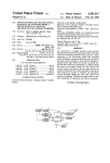
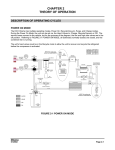
FIG. 1 is a block diagram of a computer system
which has a hard disk drive and suspend/resume capa
during the suspend operation because of the fact that
bility, and which embodies the present invention;
power to the drive circuitry is turned off, it is important
FIG. 2 is a ?owchart of pertinent portions of an inter
rupt service routine executed by a processor which is a
50
that the exact status of the hard disk drive prior to the
suspend operation be stored before the suspend, and 55 component of the system of FIG. 1;
that this status be restored in the hard disk drive when
FIG. 3 is a ?owchart of pertinent portions of a pro
gram executed by a microprocessor in the hard disk
drive of FIG. 1;
operation subsequently resumes. Otherwise, the hard
disk drive will operate differently after the suspend
operation than it did before the suspend operation,
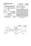
FIG. 4 is a ?owchart of an alternative embodiment of
which in turn may cause the application program to
the program represented by the ?owchart of FIG. 3;
operate differently and/or improperly, which would
obviously defeat the entire purpose of the suspend
and
FIG. 5 and 6 are flow charts respectively similar to
FIGS. 2 and 3 but showing another alternative embodi
ment of the invention.
/resume capability.
Consequently, it is important for the hardware of a
computer system (including the ?rmware in read only
memory) to be designed so that it maintains externally
of the hard disk drive a record of the speci?c settings to
which the drive has been programmed. Thus, in a tradi
65
DETAILED DESCRIPTION
Referring to FIG. 1, a computer system 10 includes a
central processing unit (CPU) 11, a push-button switch.
3
5,394,527
12 which is coupled to the CPU 11, a conventional
computer keyboard 13, a main memory 16, a hard disk
drive 17 and a power supply 18. The hard disk drive 17
is electrically coupled to the rest of the system 10
through one or more cables, which in the preferred
embodiment are conventional and are collectively rep
resented in a diagrammatic form at 19.
The power supply 18 includes a power source 20
which is a rechargeable battery in the preferred embodi
ment, and which supplies DC power to the CPU 11 at
21, to the main memory 16 at 22, and to the hard disk
drive 17 through a selectively actuable electronic
power switch 23.
In the preferred embodiment, the CPU 11 includes
two separate microprocessors, namely a main process
ing unit (MPU) 26 and a system control processor
(SCP) 27. The SCP 27 is provided to take some of the
processing burden off the MPU 26, and persons of ordi
nary skill in the art will recognize that the SCP could in
fact be omitted and that the MPU 26 could perform all
processing functions of the CPU 11. Of course, the
system operates faster and more ef?ciently when both
the MPU 26 and SCP 27 are present.
The MPU 26 is, in the preferred embodiment, an Intel
80386 SL microprocessor manufactured by Intel Cor
poration of Santa Clara, Calif, along with typical asso
4
memory 16 and to the hard disk drive 17. The MPU 26
also provides refresh control signals 56 for the main
memory 16, which in the preferred embodiment is im
plemented with dynamic random access memory com
ponents (DRAM).
The internal structure of the hard disk drive 17
shown in FIG. 1 is exemplary, and there are variations
of it which are compatible with the present invention.
In FIG. 1, the hard disk drive 17 includes a micro
processor 71, which could be almost any conventional
and commercially available microprocessor. The mi
croprocessor 71 generates the previously mentioned
!LED signal on line 32 and the HDINT signal on line
46. The hard disk drive 17 includes an LED 72, which
is connected between the line 32 and a source of power.
Thus, when the line 32 carries a logic low voltage, the
LED 72 will be illuminated, whereas when the line 32
carries a logic high voltage, the LED 72 will not be
illuminated. The LED 72 is used to provide a visual
indication of when the hard disk drive 17 is carrying out
a command.
The microprocessor 71 generates address and control
signals on respective address and control buses 76 and
77, and sends and receives data on a bidirectional data
25 bus 78. The data bus 78 is connected to inputs of an
ciated support circuitry. This particular microprocessor
eight-bit register 81 and an eight-bit register 82, and
outputs of these registers are connected through respec
has some special features which will be discussed in
more detail later. The SCP 27 could be implemented
with almost any conventional and commercially avail
tive three-state buffers 83 and 84 to the system data bus
53. The system data bus 53 is connected to inputs of an
able microprocessor and its associated support circuits.
The keyboard 13 is entirely conventional, and is cou
eight-bit register 86 and an eight-bit register 7, and the
outputs of these registers are coupled through respec
tive three-state buffers 88 and 89 to the disk data bus 78.
pled through a conventional cable 31 to the SCP 27.
The register 82 includes a DRQ bit 91 and a BSY bit 92,
The SCP 27 also receives from the hard disk drive on a
which will be discussed in more detail later.
line 32 a signal !LED, which will be described in more 35
The system address and control buses 51 and 52 are
detail later. The exclamation point (l) in front of the
signal name indicates that the signal is active low. The
type. The decoding circuit 94 has four outputs 96-99,
SCP 27 produces an output signal ENABLE on a line
and can selectively actuate one of these outputs in re
connected to a decoding circuit 94 of a conventional
33, which is coupled to one input of a two-input AND
sponse to respective predetermined combinations of
gate 36, the other input of which is coupled to the line 40 signals on the address bus 51 and control bus 52. When
32 from the hard disk drive which carries the signal
actuated, the output 97 enables the three-state buffer 84
!LED. The SCP 27 also outputs a signal INT on a line
so that the contents of register 82 are placed on the
37, which is coupled to one input of a two-input OR
system data bus 53. When output 96 is enabled, the
gate 38, the other input of which is coupled to the out
three-state buffer 83 is enabled so that the contents of
put 39 of the AND gate 36. The output 41 of the OR 45 register 81 are placed on the system data bus 53. When
gate 38 is coupled to the input of a three-state buffer 42,
output 99 is actuated, the data present on system data
which is always actuated. The output 43 from the three
bus 53 is loaded into the register 87, and when output 98
state buffer 42 is connected to an interrupt input EX
is enabled, the data on the system data bus 53 is loaded
TSMI of the MPU 26. The line 32 is already present in
into the register 86.
conventional cables of the type shown diagrammati
Associated with the microprocessor 71 is a similar
cally at 19, and thus use of this line to create an interrupt
decode circuit 104 of a conventional type. The decode
according to the present invention avoids the expense
circuit 104 has several outputs, including four outputs
and inconvenience of non-standard cabling while ensur
106-109. When the output 106 is actuated, it enables the
ing that the cabling and disk drive both remain fully
three-state buffer 88 so that the contents of register 86
compatible with pre-existing systems.
55 are placed onto the disk data bus 78. When the output
An interrupt signal HDINT supplied by the hard disk
107 is actuated, it enables the three-state buffer 89 so
17 on a line 46 is coupled to a further interrupt input
that the contents of register 87 are placed onto the disk
IRQ of the MPU 26.
data bus 78. When the output 108 is actuated, the data
The MPU 26 produces on an output line 47 a power
on disk data bus 78 is loaded into the register 81, and
control signal PWRCTL, which is connected to a con 60 when the output 109 is actuated, the data on disk data
trol input of the electronic power switch 23. When the
bus 78 is loaded into register 82.
signal PWRCTL is in respective logical states, the elec
The hard disk drive 17 also includes a read only mem
tronic power switch 23 respectively permits and pre
ory (ROM) 112, which is coupled to the address, con
vents the application of DC power to the hard disk
trol and data buses 76-78, and which can be selected by
drive 17. The MPU 26 outputs address and control data 65 an output 113 from the decode circuit 104. The ROM
on respective buses 51 and 52, and sends and receives
data on a bidirectional data bus 53. The address bus 51,
control bus 52 and data bus 53 are coupled to the main
112 contains a program which is executed by the micro
processor 71, along with some data constants which are
used by the program. The hard disk drive 17 further
5
5,394,527
includes a random access memory (RAM) 116, which is
coupled to the address, control and data buses 76-78
and to select lines 117 from the decode circuit 104. The
microprocessor 71 can dynamically store data in and
retrieve data from the RAM 116 while it is executing
the program provided in the ROM 112. The data bus 78
and some select lines 122 from the decode circuit 104
are connected to a physical drive section 121. The phys
ical drive section 121 includes conventional and not
illustrated components such as one or more rotating
magnetic platters, one or more movable read/write
heads each engageable with a platter surface, a mecha
6
Another special feature is that the MPU 26 has, in
addition to a standard interrupt handling structure
which can be triggered by an event such as actuation of
the IRQ input by a signal on line 46, a special service
management interrupt which can be triggered by man
ual actuation of the push-button switch 12 or by actua
tion of the EXTSMI input by the signal on line 43.
Upon the occurrence of a service management inter
rupt, the internal hardware of the MPU 26 automati
cally stores in a special reserved management portion
126 of the main memory 16 every facet of the current
operational state of the MPU, including all internal
nism for moving each head relative to its platter, and
registers and ?ags. The MPU 26 is then automatically
the electrical support circuitry for each head.
placed in a non-protected operational mode, and begins
The CPU 11 uses the register 86 to send commands to 15 execution of a special service management interrupt
the disk drive 17, and uses the register 87 to pass data to
handling routine provided in the management portion
the disk drive 17. The disk drive 17 uses the register 81
126 of the main memory 16. Thus, if the MPU 26 is
to pass data to the CPU 11, and maintains in the register
operating in protected mode for a particular application
82 certain status information, such as the DRQ bit 91
at the point in time when it is interrupted, the entire
which is set when the disk drive 17 is carrying out a 20 status of the MPU at the time of the interrupt is saved,
command and the BSY bit 92 which can be repeatedly
including the existence of the protected mode, the spe
set and reset as a command is carried out to provide
cial handling routine for the interrupt is then executed
handshaking information which facilitates a transfer of
data between the CPU 11 and disk drive 17. The !LED
in non-protected or “real” mode, and then as control is
returned to the interrupted application program the
line 32 is set to a logic low voltage at the start of a 25 entire stored status of the MPU, including the existence
command to turn on the LED 72, and is switched back
of protected mode, is restored. Thus, the handling of the
to a logic high voltage when the command concludes,
as described in more detail later. The HDINT signal is
used during execution of commands to interrupt the
application program in the CPU 11, for example to
effect the transfer of each of several blocks of data
between the CPU 11 and the hard disk drive 17.
The present invention involves changes to the pro
gram stored in the ROM 112 but, aside from this, the
hard disk drive 17 is structurally conventional in all 35
respects.
As mentioned above, the main processing unit (MPU)
26 has some special features. These features are inherent
and integral to the commercially available microproces‘
interrupt is invisible to the application program and
does not affect the status of its protected mode, but
during the special handling routine the MPU operates in
real mode without the limitations of the application
program’s protected mode, and thus has virtually unre
stricted access to the system in order to carry out its
pertinent task.
A further special feature of the MPU 26 is that it has
a status bit shown diagrammatically at 128 and a special
software instruction which, when executed, causes the
MPU 26 to enter a suspend state in which it halts and
internally shuts off power to almost all of its circuitry,
except for a few portions such as the portion which
sor used for the MPU 26, and are not in and of them 40 generates the refresh control signals 56. When the push
selves the focus of the present invention. Nevertheless,
button switch 12 is manually deactuated while the MPU
these special features are brie?y described here in order
26 is in this suspend state, the MPU 26 automatically
to facilitate a thorough and accurate understanding of
turns all of its internal power back on, sets the status bit
the present invention.
128 to indicate that it has been in the suspend state, and
More speci?cally, it is important to understand that 45 then initiates a self-reset which does not affect the status
the MPU 26 is a protected mode microprocessor. When
bit 128 but is otherwise similar to the manner in which
operating in the protected mode, the MPU 26 typically
the MPU 26 responds to a system reset generated exter
does not have unrestricted control of the system. As a
nally to itself. When the hardware transfers control to a
speci?c example, the main memory 16 might at some
software routine at a predetermined address following
speci?c point in time include a multi-tasking operating 50 each such reset, the software routine can check the
system such as 05/2 or UNIX, a ?rst application pro
status bit 128 to see whether or not the reset was caused
gram such as a word processor, and a second applica
by an exit from the suspend state. It is emphasized again
tion program such as a spreadsheet. When the operating
that the special features of the MPU 26 discussed above
system turns control of the MPU 26 over to the ?rst
are inherent and integral to the commercially available
application program, it would place the MPU 26 in a 55 microprocessor used for the MPU 26, namely the Intel
protected mode which prevents the MPU 26 from
80386 SL microprocessor. Therefore, these features
changing some of its own internal registers which con
have been only brie?y described for purposes of conve
trol protected mode and from changing portions of the
nience.
main memory 16 which contain the operating system
As mentioned above, the management portion 126 of
and the second application program. Similarly, as the
the main memory 16 includes a special interrupt han
operating system is turning the MPU 26 over to the
dling routine for the service management interrupt.
second applications program, it places the MPU 26 in a
FIG. 2 is a ?owchart showing portions of this interrupt
protected mode which prevents the second application
handling routine which embody features of the present
program from doing certain things such as changing the
invention.
internal registers of the MPU which control protected 65 More speci?cally, at the top of FIG. 2, block 131
mode or changing the portions of main memory 16
indicates the occurrence of a service management inter
storing the operating system and the ?rst application
rupt, for example due to actuation of the switch 12, due
program.
to actuation of the line 43, or due to the occurrence of
7
5,394,527
some other condition. As mentioned above, the occur
rence of this interrupt causes the hardware of the MPU
26 to automatically save the entire current status of the
8
line 32 which actuated line 43, and will thus proceed at
136 to block 146. It should be noted that, if it had been
determined in block 141 that the DRQ bit was not set,
MPU in the management portion 126 of the main mem
or in other words that the hard disk drive 17 was not in
ory 16, including all internal registers and status ?ags.
Although this is performed by the hardware and is
technically not a part of the software interrupt handling
the middle of an operation, control would have been
transferred at 147 directly from block 141 to block 146.
routine, it is shown in block 132 of FIG. 2 for clarity
and in order to facilitate an understanding of the present
invention. Control is then transferred to the software
interrupt handling routine in the portion 126 of the main
memory, beginning with block 133 of FIG. 2. In block
133, the handling routine checks certain status ?ags in
order to determine the source of the interrupt, or in
other words whether it was caused by actuation of the
switch 12, actuation of the line 43, or some other event.
If it was caused by actuation of the switch 12 or by
In either case, at block 146 the MPU 26 uses the ad
dress, control and data buses 51-53 to load a SUS
PEND command into the register 86 of the hard disk
drive 17. The response of the hard disk drive to this
command will be described in more detail later, but in
general this command noti?es it that the system 10 will
be entering suspend mode, and causes it to formulate in
the RAM 116 a 512 byte block of data which contains
every facet of its current status, including all ‘registers
and ?ags. Meanwhile, the MPU 26 has proceeded to
block 147 in FIG. 2, where it uses the address, control
actuation of the line 43, then control proceeds as respec
and data buses 51-53 to load a REQUEST command
tively shown at 134 or 136, whereas if the cause was
into the register 86. In a manner described in more
some other event control proceeds as shown at 136-139 20
detail later, this causes the microprocessor 71 to succes
to respective routines which are not pertinent to the
sively send all 512 bytes of the data block it has formu
present invention and are thus not illustrated or de
lated in the RAM 116 through the register 81 to the
scribed.
MPU 26. Meanwhile, at block 148 in FIG. 2, the MPU
Assuming that the interrupt was caused by manual
actuation of the switch 12, which indicates that the 25 26 accepts this 512 byte data block, and stores it in a
reserved section of the main memory 16. Then, at 149,
system is to be placed in the suspend mode, control
the MPU 26 deactuates the PWRCTL line 47, so that
proceeds at 134 to block 141, where the MPU 26 reads
the electronic power switch 23 is disabled and shuts off
the contents of the status register 82 in the hard disk
all power to the hard disk drive 17. At this point, the
drive 17 and checks the DRQ bit 91. If the DRQ bit is
MPU could also power down other peripherals present
'set, then the hard disk drive 17 is in the middle or carry
in the system. Then, at 151 in FIG. 2, the MPU 26
ing out an operation which the interrupted application
executes the software instruction which causes it to
program initiated before it was interrupted, and thus the
enter the suspend mode, in which it halts and internally
MPU 26 must wait until the operation is completed
shuts off power to substantially all portions of its cir
before the MPU can shut down the hard disk drive 17 in
order to implement the suspend mode. In this case, the 35 cuitry.
At this point, power will have been shut off to sub
MPU 26 proceeds to block 142, where it directs the
stantially the entire system, except for the main memory
SCP 27 to actuate its enable output line 33, which ena
16, which must be maintained because it contains all of
bles the AND gate 36. Since the hard disk drive 17 is in
the stored status of the CPU 11 and hard disk drive 17,
the middle of an operation, its microprocessor 71 will be
maintaining the line 32 at a logic low level in order to 40 as well as portions of the operating system and any
application programs which were active. Also, and as
illuminate the LED 72, and thus the other input of
mentioned previously, a few small portions of the MPU
AND gate 36 will be disabled. Then, at block 143 and
26 still receive power and remain active, including the
44, control is returned to the interrupted application
portion which supplies refresh control signals at 56 to
program, block 143 representing the automatic restora
tion by the MPU hardware of the status which was 45 the main memory 16, and the portion which monitors
the switch 12 so that, when the switch 12 is deactuated,
stored in portion 126 of main memory 16 at block 132 of
the MPU 26 can be automatically brought out of sus
FIG. 2. Like block 132, block 143 is included in the
pend mode. So long as suspend mode is in effect, the
flowchart of FIG. 2 for clarity, even though it is techni
MPU 26 remains halted at block 151 in FIG. 2.
cally performed by the MPU hardware rather than by
Manual deactuation of the push-button switch 12 is
software of the interrupt service routine. Since control
treated differently by the MPU 26 than actuation
has now been returned to the interrupted application
thereof. In particular, where actuation of the switch 12
program, the application program continues to execute
produces a service management interrupt, deactuation
while the hard disk drive 17 completes the operation
which is in progress.
does not produce another interrupt. Instead, deactua
tion of the switch 12 causes the MPU 26 to automati
When the hard disk drive 17 completes the operation
in progress, it switches the line 32 to a logic high level
cally restore internal power to itself, to then set the
to turn off the LED 72, as a result of which both inputs
special internal status bit shown diagrammatically at
of the AND gate 36 will be at a logic high level, and
128 in FIG. 1, and to then initiate a self-reset which does
thus the output 39 of the AND gate 36 will be actuated
not affect the status bit 128 but which forces the MPU
and in turn will actuate one input of the OR gate 38,
26 into real mode and causes the MPU 26 to transfer
causing the OR gate 38 to actuate its output 41 and thus
control at 153 to a block 154. Block 154 is the start of a
the line 43 so that another service management interrupt
software routine which can also be entered at 155 in
is generated at the EXTSMI input of the MPU 26.
response to a power-up reset. At block 154, the software
Consequently, the application program will again be
checks the status bit 128 and other similar indicators in
interrupted and, at 131 and 132 in FIG. 2, the entire
order to determine the cause of the reset. In the event
status of the MPU 26 will again be stored in the portion
the status bit 128 is set, block 154 would be exited at 157 .
126 of the main memory 16. Then, at 133, the MPU will
If the status bit were not set, control would be trans
determine that the interrupt was caused by a change on
ferred as shown diagrammatically at 161-164 to one or
5,394,527
more other routines which are not pertinent to the pres
ent invention and are thus not illustrated and described.
The transfer at 157 to block 166 represents a branch
from the software reset handling routine to the special
interrupt handling routine in the portion 126 of main
10
For example, in the case of a transfer of a block of
data from the MPU 26 to the hard disk in the physical
drive 121, the microprocessor 71 can toggle the busy bit
BSY 92 in the register 82 to provide an indication of
when it is ready to accept each byte, and the MPU 26
memory 16. At block 166, the MPU 26 deactuates the
can monitor the BSY bit and load an additional byte
signal PWRCTL on line 47 so that the electronic power
into the register 87 each time the BSY bit is cleared. The
switch 23 again supplies power to the hard disk drive
microprocessor 71 initially stores these received bytes
17. At this point, the MPU 26 would also turn on power
to other not-illustrated peripherals which may be pres
ent, such as a display and/or a ?oppy disk drive. Then,
at block 167, the MPU 26 uses the address, control and
in the RAM 116. After a predetermined number of
bytes have been transferred, which may for example be
equal to the number of bytes in a sector of the hard disk,
the MPU 26 may return to other processing while the
data buses 51-53 to load a RESTORE command into
microprocessor 71 retrieves these bytes from the RAM
the register 86 of the hard disk drive 17, to indicate to
11.6 and stores them on the hard disk in the physical
the hard disk drive 17 that it will be receiving a block of
drive section 121. Then, the microprocessor 71 can send
512 bytes to use in restoring its status. Then, the MPU
an HDINT signal on the line 46 in order to interrupt the
26 retrieves from the main memory 16 the 512 byte data
MPU 26, causing the MPU 26 to send another portion
block stored there at block 148 of FIG. 2, and succes
of the data block which is to be stored. This is all repre
sively transmits these 512 bytes across the data bus 53
sented diagrammatically in FIG. 3 by the broken line
and through the register 87 to the microprocessor 71. 20 187.
After receiving this entire data block, the microproces
Toward the end of execution of the command, micro
sor 71 restores the status of the hard disk drive 17 from
the information in the data block, so that the hard disk
drive 17 is now in precisely the state it was in before it
processor 71 reaches a point at block 188 where it sets
the BSY bit 92 in the register 82 for the last time, for
lost power. In FIG. 2, the hardware of the MPU 26 25 example where it has accepted from the MPU 26 the
very last byte to be stored. It then proceeds to store this
automatically restores at 169 the complete status of the
information on the hard disk in the physical drive sec
MPU 26 which has been stored in the management
tion 121 and to do any associated ?nal housekeeping,
portion 126 of the main memory 16, and of course the
and at some point during this process it clears the DRQ
interrupted application program is still resident in the
main memory 16, along with all other programs which 30 bit 91 in the status register 82, and at block 191 changes
the line 32 to a logic high level to the turn the LED 72
are active. Thus, at 171, the application program re
off. Thereafter, at 192, the microprocessor 71 clears the
sumes executing without any knowledge that the sys
BSY bit 92 in the register 82. It is a requirement of the
tem has been substantially shut down and restarted. The
present
invention that, at the completion of a command,
application program continues as if it has never been
interrupted in the ?rst place.
35 the LED 72 be turned off before the BSY bit in the
register 82 is cleared, for the following reason.
FIG. 3 is a ?owchart showing portions of the pro
As described above, when the system 10 is attempting
gram which is stored in the ROM 112 of FIG. 1 and
to enter the suspend mode in response to actuation of
which is executed by the microprocessor 71 of hard disk
the push-button switch 12, the MPU 26 checks the
drive 17 during the foregoing procedure. A power-up
reset situation causes execution to start at 176, and to 40 DRQ bit at block 141 in FIG. 2. If the microprocessor
71 is in the middle of a command, for example at 187 in
proceed to 177 where, as shown diagrammatically at
FIG. 3, the DRQ bit will be set, and thus as described
178, the microprocessor 71 waits for the CPU 11 to load
above in association with block 142-144 of FIG. 2, the
a command into the register 86. When a command is
MPU 26 will enable the line 33 in FIG. 1 and then
loaded into the register, control proceeds to one of
several different routines in dependence on the speci?c 45 return control to the application program to wait for the
hard disk drive 17 to complete what it is doing. It is
command. In particular, if the command is a SUS
important that the application program not be able to
PEND command or a RESTORE command, control
instruct the hard disk drive 17 to start a new command.
proceeds as shown respectively at 179 and 181, whereas
So long as the BSY bit is set, the application program
other commands which are conventional cause control
to proceed along respective paths designated at 182, 183 50 which the MPU 26 is executing will not try to send the
hard disk drive 17 a new command. Further, as also
and 184. For purposes of the present invention, it is
described above, when the microprocessor 71 turns off
sufficient to brie?y describe one of these other com
the LED 72 using line 32, the same signal will propo
mands, for example the command corresponding to a
gate through gates 36 and 38 to create another service
transfer at 183 to block 186. This might, for example, be
a command instructing the hard disk drive 17 to accept 55 management interrupt which returns control of the
MPU 26 to the service management interrupt routine of
a block of data from the CPU 11 and to store this data
on the hard disk of the physical drive section 121. At
FIG. 2, at which point the application program no
longer has control of the MPU 26 and thus cannot tell
186, the microprocessor 71 sets the line 32 to a logic low
level in order to turn the LED 72 on, the LED provid
the hard disk drive 17 to begin a new command. There
ing visual indication that the hard disk drive is carrying
fore, with reference to blocks 191 and 192 in FIG. 3,
keeping the BSY bit set at the end of the command until
the LED 72 is turned off ensures that the BSY bit will
keep the application program from starting a new com~
out an operation. Then, the microprocessor 71 loads the
status register 82 with a word which has the effect of
setting the DRQ bit, so that if the MPU 26 reads the
register 82 the DRQ bit will indicate that the hard disk
mand until the deactuation of the LED occurs and
drive 17 is carrying out an operation. Then, as indicated 65 creates an interrupt which shifts control of the MPU 26
diagrammatically by the broken line at 187, the micro
from the application program to the interrupt handling
processor 71 carries out the speci?c steps necessary to
routine, which can then proceed with the suspend oper
carry out the command.
anon.
11
5,394,527
12
At this point, the interrupt handling routine would
hard disk in block 214, and then restores from this
proceed to block 146 in FIG. 2 where, as described
stored data at block 219 every facet of the status which
above, the MPU 26 sends the hard disk drive 17 a SUS
the hard disk drive 17 had before its power was turned
PEND command. In FIG. 3, this causes the micro
off. Then, at block 221, it accepts the 512 bytes which
processor 71 to proceed at 179 from block 177 to block 5 the MPU 26 sends, but it simply discards this data be
193, where it collects every facet of its current status
cause it has no need for it.
and formulates in the RAM 116 a 512 byte block of data
FIGS. 5 and 6 are ?ow charts which are respectively
which includes all of this status. The status may take up
similar to FIGS. 2 and 3 but show another alternative
only a portion of the 512 available bytes, and the re
embodiment of the invention. Elements in FIGS. 5 and
maining bytes can in fact be “garbage”. Then, at block
6 which are equivalent to elements in FIGS. 2 and 3 are
194, the microprocessor waits for a request command
designated with the same reference numerals used in
from the MPU 26, as shown diagrammatically at 196.
FIGS. 2 and 3. Only the differences are described in
Meanwhile, MPU 26 proceeds from block 146 to block
detail below.
1
147 in FIG. 2, where it sends the REQUEST command.
More speci?cally, in the embodiment of FIGS. 2 and
In response to the REQUEST command, the micro 15 3, it is a requirement that the hard disk control its LED
processor 71 proceeds from block 194 in FIG. 3 to
line in a speci?c manner, in particular by promptly
block 197, where it transmits through the register 81 to
the MPU 26 the 512 byte block of data it has formulated
in the RAM 116. Then, at block 198, the microproces
deactuating it as soon as the current command has been
completed. There are some disk drives which may have
dif?culty with this approach, but on the other hand it is
sor 71 halts, and waits for the MPU 26 to use the elec 20 possible to send these drives a command while they are
tronic power switch 23 to shut off power to the hard
in the process of executing another command. Thus, in
disk drive 17 in the manner already described above.
FIG. 5, regardless of whether it is determined in block
When the MPU 26 eventually exits from the suspend
141 of FIG. 5 that the DRQ bit is set, a SUSPEND
mode, it will use the electronic power switch 23 to turn
command is immediately sent to the disk drive at 241 or
the power to the hard disk drive 17 back on, as dis 25 242. In the event the drive is busy and the system has to
cussed above in association with block 166 in FIG. 2. In
wait for it to ?nish what it is doing and then service
FIG. 3, this produces a power-up reset event which
another SMI, when control proceeds along arrow 136 it
forces the microprocessor 71 to block 176 in FIG. 3,
will not be necessary to send the SUSPEND command
following which the microprocessor 71, typically after
again.
doing some initialization, proceeds to block 177, where
it waits at 178 for a command from the MPU 26. Mean
while, the MPU 26 proceeds to block 167 in FIG. 2,
where it loads the RESTORE command into the regis~
ter 86 of the hard disk drive 17. This causes the micro
In FIG. 6, receipt of the SUSPEND command causes
control to proceed at 243 to block 244, where the disk
drive enters a mode where it stops accepting further
commands other than the REQUEST command. While
waiting for the REQUEST command, the drive com
processor 71 to proceed at 181 from the block 177 to the 35 pletes the activity which is already in progress. Then it
block 201, where it accepts the 512 byte block which
deactuates its LED line in order to indicate that at some
the MPU 26 is transmitting in block 168. This is, of
course, precisely the 512 byte block which the micro
point the activity has been completed, after which the
processor sends the REQUEST command. In response
processor 71 sent to the MPU at block 197, and thus at
to the REQUEST command, the disk drive formulates
block 202 the microprocessor 71 can use the data in this 40 the 512 byte block at 193, then resumes accepting all
block to completely restore every facet of the status
commands at block 245, and then at block 197 transmits
which was present in hard disk drive 17 before its
the 512 byte block to the processor.
power was turned off.
Preferred embodiments of the invention have been
FIG. 4 is a ?owchart-showing an alternative embodi
disclosed and described in detail, but it will be recog
ment of the program of FIG. 3. Equivalent elements in 45 nized that there are variations or modi?cations of the
FIGS. 3 and 4 are designated with identical reference
disclosed embodiments which lie within the scope of
numerals. Only the differences are described in detail
the present invention.
below.
The embodiments of the invention in which an exclu
More speci?cally, in response to the SUSPEND
sive property or privilege is claimed are de?ned as
command, the microprocessor 71 proceeds at 179 from SO follows:
block 177 to block 211 of FIG. 4. In block 211, the
microprocessor collects every facet of its status. Then,
1. An apparatus comprising: a processor having an
interrupt input; a disk drive having means for output
in block 212, the microprocessor 71 waits for the RE
ting a light element control signal which can have ?rst
QUEST command from the MPU 26, as shown dia
and second states respectively indicating that said disk
grammatically at 213. When the REQUEST command 55 drive is active and inactive; and selectively actuable
is received, the microprocessor 71 proceeds to block
means for respectively effecting and preventing appli
214, where it 'stores the collected status on a reserved
cation of said light element control signal from said disk
portion of the hard disk in its own physical drive section
drive to said interrupt input of said processor when said
121. Then, at block 216, it transmits 512 bytes to the
selectively actuable means is respectively actuated and
MPU 26. These 512 bytes may be unde?ned “garbage”
deactuated, said processor including means for selec
data, and are transmitted only for purposes of compati
tively actuating and deactuating said selectively actu
bility because the MPU 26 expects to receive and store
able means.
512 bytes. Then, the microprocessor 71 halts at 217 and
2. An apparatus of claim 1, wherein said processor
waits for its power to be turned off.
has a selectively actuable output; and wherein said se
After power is turned back on, the microprocessor 71 65 lectively actuable means includes an AND gate having
receives the RESTORE command from the MPU 26,
one input coupled to said output of said processor and a
and proceeds at 181 from block 177 to block 218, where
second input coupled to said light element control sig
it retrieves the status information which it stored on the
nal from said disk drive, and means coupling said output
13
5,394,527
of said AND gate to said interrupt input of said proces
14
response to detection of a change in said light element
control signal from said first state to said second state
sor.
3. An apparatus of claim 1, including a cable coupled
when said predetermined operational condition is pres
to said disk drive and having a plurality of conductors,
eat.
one of said conductors carrying said light element con 5
6. A method of claim 5, including the step of execut
trol signal from said disk drive and being connected at
ing a program in said processor which selectively
an end of said cable remote from said disk to said selec
changes an output signal from said processor between
tively actuable means.
?rst and second logical states, said checking step includ
4. An apparatus according to claim 1, including light
ing the steps of monitoring said output signal from said
emitting means for respectively emitting and not emit 10
processor
and determining that said predetermined op
ting visible light when said light element control signal
erational
condition
is present when said output signal
respectively has said ?rst and second states.
has said ?rst logical state.
5. A method of operating a system which includes a
7. A method of claim 5, wherein said system includes
processor having an interrupt input and includes a disk
drive outputting a light element control signal which 15 a light emitting element, and including a step of energiz
ing said light emitting element so that it emits visible
can have ?rst and second states, including the steps of:
light when said light element control signal has said ?rst
checking for the presence of a predetermined opera
state, and deenergizing said light emitting element to
tional condition; monitoring said light element control
signal when said predetermined operational condition is
prevent emission of light therefrom when said light
present to detect a change from said ?rst state to said
element control signal has said second state.
second state thereof; and interrupting said processor in
*
25
30
35
45
55
65
*
*
*
*