1
United States Patent [19]
[11]
[45]
Higgins et al.
[54]
Motorola——MCl46805G2—CM)S 8-Bit Microcom
Inventors: Mary L. Higgins; David L. Muri,
both of Sunrise, Fla.
puter.
Motorola—MCM2802-MOS—32>< 32 Bit Electrically
Motorola-User’s Manual——M6805-—M146805 Family
Microcomputer/Microprocessor.
Erasable Programmable Read Only Memory.
Foreign German Manual—Kodieraleitung Funftonfol
ge-Baustein FK IOZ-FK 103.
Primary Examiner—Jin F. Ng
Attorney, Agent, or Firm—Jerry A. Miller; James W.
Gillman; Edward M. Roney
[57]
US. Cl. ...................................... .. 455/78; 455/35;
ABSTRACT
455/38; 455/116; 340/825.44; 340/345
In a transceiver, a multiple function switch decoder
Field of Search ..................... .. 455/31, 32, 34, 35,
includes means for detecting actuation of the switch and
means for monitoring the status of the receiver. A timer
responsive to the monitoring means and detecting
means establishes a predetermined time interval follow
ing each switch actuation or each received message of
predetermined type. When the switch is actuated dur
ing the time interval the transmitter is enabled. When
the switch is activated outside the time interval the
455/38, 77, 78, 79, 84, 116, 91; 375/7, 68, 70;
340/309.15, 345, 696, 825.44; 370/32
[56]
Feb. 19, 1985
Motorola—MCl4022B~—CMOS MSI.
H04Q 7/00
[58]
4,501,017
SWITCH CONTROLLER FOR OBTAINING A
PLURALITY OF FUNCTIONS FROM A
SINGLE SWITCH IN A TWO-WAY
TRANSCEIVER AND METHOD THEREFOR
[73] Assignee: Motorola, Inc., Schaumburg, 11].
[21] Appl. N0.: 462,486
Jan. 31, 1983
[22] Filed:
[51] Int. Cl.3 ....................... .. H04B 1/44; H04B 1/02;
[52]
Patent Number:
Date of Patent:
References Cited
U.S. PATENT DOCUMENTS
3,500,458
3/1970
3,500,459
3/1970 Battin et a1.
Cannalte ............................. .. 455/79
455/78
3,943,444 3/1976 Lundberg
455/32
4,037,158
7/1977
455/79
4,072,898
2/1978 Hellman et al.
4,396,910
8/1983
Eastmond .... ..
receiver audio is activated so the user may monitor the
channel. During the ?rst switch actuation in any given
time interval an encoder is enabled. On subsequent
switch actuations during the same time interval the
encoder is inhibited. This allows a single switch to per
form a plurality of transmitter and receiver functions.
340/696
Enemark et al. ............. .. 340/309.l5
OTHER PUBLICATIONS
Motorola—MX 300 Series-“Handie-Talkie” Portable
Radios.
31 Claims, 6 Drawing Figures
SWITCH
6O
SOUELCH
CIRCUIT
75
CONTROLLER
G5
135 J
we
no
‘
o.c.
U.S. Patent Feb. 19,1985
____
H
_______--_
H j
)
)
Sheet3of6
HA
HR “H
__
“A
4,501,017
_____‘
HP"
an
I
2
.Ls
l IFS
T12
U.'S. Patent Feb. 19,1985
Sheet4of6
GNP
Fm.
m
062 ‘
muz mw o
IUGDOM.ZDOE
4,501,017
US. Patent Feb. 19,1985
Sheet50f6
4,501,017
INITIALIZE I400
TIMER AND
COUNTER
550
420
DISABLE
COUNTER
A R] R
CLOCKS T0
ISRESEEW
COUNTER
_
@—>—<
ENABLE
AUDIO
6605 f
-
f 450
I
DELAY
66a COUNTER
CLOCK
T|MER
INTERVAL
ENABLE TIMER
EXPLRED 670
AND AUDIO
-
f 470
ENABLE
I
YES
656‘
\
I “i
RESET
TIMER
I
68°
TIMER
4,501,017
1
2
section audio so that the user may determine if there is
SWITCH CONTROLLER FOR OBTAINING A
PLURALITY OF FUNCTIONS FROM A SINGLE
SWITCH IN A TWO-WAY TRANSCEIVER AND
METHOD THEREFOR
BACKGROUND OF THE INVENTION
1. Field of the Invention
This invention relates generally to the ?eld of control
circuits for electronic equipment. More particularly,
this invention relates to a controller which permits a
single switch to perform a plurality of transceiver func
tions which may be dependent upon the status of the
activity taking place on the desired radio frequency
channel. When the channel is clear, the user actuates a
second switch which transmits an appropriate code
word in tones or binary digits, as for example, a set of
?ve sequential tones of predetermined length and fre
quency, to access the desired receiver. The user then
actuates a third switch to enable his transmitter and
microphone in order to carry on normal conversation.
In the above transceiver scheme, a total of three
switches are required to perform even the most basic
selective calling transceiver functions. In addition to
these controls, the transceiver must also include a vol
receiver or the transmitter, or the recent actuation his
ume control, an on/off switch, a squelch control, a
15
tory of the switch itself.
'
channel selector control, and quite possibly many other
2. Background of the Invention
As the state of the art in the electronic industry pro
gresses, the trend is towards ever smaller electronic
devices which must reliably perform a variety of func
tions. An example of this trend may be found in the ?eld
of electronic calculators. Whil‘e the predecessor of the
modern pocket calculator literally occupied rooms,
devices with similar computational power which will ?t
in a shirt pocket are now commonplace. Such devices
often have control buttons which electronically address 25
a number of different features per button in order to
provide the user with a large number of features in a
controls such as a telephone style keypad for more
sophisticated transceivers. It is evident that utilizing
three separate switches simply to control the sequence
of steps necessary for initialization of a conversation is
highly inefficient. As these transceivers incorporate
more and more features and options, the switch require
ment becomes a severe size limitation in a portable or
mobile transceiver.
Another scheme often used in portable transceivers,
such as Motorola’s European version of its MX3OO
series of transceivers, utilizes a momentary push-to-talk
small package. This is accomplished by using a “second
type switch in conjunction with a three position toggle
feature button‘ which is actuated prior to the actuation
switch. This exempli?es the utilization of a two switch
of a button which addresses a plurality of features. 30 requirement for the selection of any transceiver func
tion. In this scheme a ?rst position of the toggle switch
Therefore, in order for the user to address the features
of his calculator, two button actuations are required to
places the radio receiver in a coded squelch mode. This
address a single feature.
makes the radio reciever responsive only to tone or
In the ?eld of portable radio transceivers, there is a
digitally encoded messages bearing an appropriate user
similar size reduction trend taking place. As the size of 35 address code. The center position of the toggle switch
these devices diminishes, the number of control features
places the receiver in the carrier squelch mode which
incorporated in a single control switch must also in
allows the receiver to turn on its audio ampli?er and
crease in order for the user to control the additional
speaker upon receipt of any message on the communica
electronic features incorporated therein.
tion channel without regard to coding. The third posi
This is particularly true for selective calling portable 40 tion of the toggle switch enables the transmitter and
radio transceivers (radio transmitter/receivers) such as
transmits the encoded message required .to access a
those commonly used throughout Europe. In these
receiver or repeater.
systems the user is required by regulation to monitor his
In operation, if the user wishes to initiate a call he
receiver prior to making any transmission to assure that
switches the toggle switch from the coded squelch
there is no channel activity taking place on the commu 45
position to carrier squelch position in order to monitor
nication channel he intends to use. Once the user estab
the channel for activity by other users. He then moves
lishes that the channel is free of activity, he must nor
the
toggle switch to the encode mode to transmit an
mally transmit a series of tones or a digitally encoded
message in order to address the receiver or repeater he
desires to contact. For example, in the well known
ZVEI (Zentral Verband der Elektro-Industrie) system
commonly used in Germany, an address code consists
of a sequence of ?ve audio frequency tones between
appropriate address code to access an appropriate re
ceiver. The user may then utilizes his “push-to-talk”
(PTT) switch in a normal manner as necessary to carry
on the desired conversation. This system has the advan
tage of forcing the user to monitor the channel prior to
transmitting the code to access a receiver since he has to
1060 Hz and 2600 Hz which are consecutively transmit
ted. Each tone has a 70 millisecond duration with no 55 pass through the carrier squelch position of the three
position switch in order to initiate a call. After complet
ing the conversation, the user must switch his trans
ceiver back to the coded squelch mode.
is repeated). Each user or repeater is assigned a ?ve
Another two switch system is used in radios such as
digit address which must be correctly decoded to access
that receiver or repeater. Encoding and decoding cir 60 the GRUNDIG MODEL FK103. In this system a ?rst
switch turns ON the receiver audio so that the user may
cuits for such systems are well known. Having estab*
pause between tones. Each tone represents a single digit
0-9 (or a repeat tone indicating that the preceeding digit
lished receiver or repeater access, the user is then free to
carry on normal two way voiceor data communica
monitor the channel. Deactuation of the switch places
the transceiver in a coded squelch mode. Actuation of
the second switch while in the coded squelch mode
One scheme often used to accomplish the above se 65 reverts the receiver to carrier squelch and transmits the
quence of steps _is to provide the portable transceiver
address code. All subsequent transmissions are without
with three switches. In operation, the user firsts actuates
encoding and the ?rst switch is actuated again to place
a “push-to-monitor” switch which enables the receiver
the radio back in the coded squelch mode.
tions with another transceiver.
I
3
4,501,017
Although these systems reduce the number of
switches required to two, operation of the transceiver
with one hand can be quite awkward. They inef?ciently
4
In another embodiment of the present invention, a
method of controlling a multiple function switch in
cludes the steps of providing a timer to establish time
intervals, detecting whether or not the timer’s output is
utilize valuable transceiver controls to actuate only
basic transceiver functions not to mention increasing
predetermined active, counting the number of switch
their cost. Also, the user is required in each case to
actuations occuring while the output is a predetermined
manually place the transceiver back in a coded squelch
signal, enabling an encoder if the count equals a ?rst
predetermined count and inhibiting the encoder if the
mode after conversation has ended.
count is equal to a second predetermined count.
The features of the invention believed to be novel are
SUMMARY OF THE INVENTION
It is an object of the present invention to provide an
improved controller for a multiple function switch.
It is another object of the present invention to inte
grate a plurality of switching functions in a single
switch for a transceiver.
set forth with particularity in the appended claims. The
invention itself however, as to organization, method ‘of
use, and method of operation, together with further
objects and advantages thereof, may be best understood
15 by reference to the following description taken in con
It is another object of the present invention to pro
vide an efficient switch scheme for initiating communi
cations with a portable transceiver in a selective calling
communications system.
It is another object of the present invention to pro
vide a controller which allows a single switch to per
form a plurality of functions in a portable transceiver as
a result of receiver conditions, transmitter conditions,
junction with the accompanying drawings.
BRIEF DESCRIPTION OF THE DRAWINGS
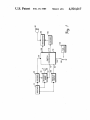
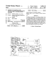
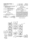
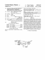
FIG. 1 is a block diagram of a hardware implementa
tion of the present invention‘ embodied in a transceiver.
FIG. 2 is a detailed electrical schematic of a hardware
and activity of the switch itself.
embodiment of the controller portion of the present
invention.
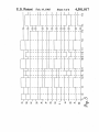
FIG. 3 is a timing diagram of the conroller of FIG. 2.
vide a controller for ef?cient utilization of switches in a
puter implementation of the present invention embod
It is a further object of the present invention to pro 25
miniature portable transceiver.
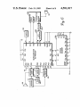
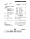
FIG. 4 is a system block diagram for a microcom
ied in a transceiver.
'
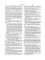
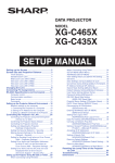
FIG. 5 is a flow chart detailing the operation of the
controller portion of the present invention.
FIG. 6 is a combined functional block diagram and
electrical schematic showing the hardware to utilize a
In one embodiment of the present invention. A trans
ceiver has a multiple function switch controller includ
ing a timer for a establishing a time interval. A ?rst
circuit produces a ?rst control signal when the switch is
preferred microprocessor embodiment of the present
actuated during the time interval, and a second circuit
invention for FIG. 4.
produces a second control signal when the switch is
actuated outside the time interval.
DESCRIPTION OF THE PREFERRED
35
EMBODIMENT
In another embodiment of the present invention, a
multiple function switch controller includes an appara
Turning now to FIG. 1, a receiver 10 is coupled to an
tus for detecting the actuation of a switch and a circuit
address decoder 20 and receives modulated coded in
for monitoring the status of a communication channel.
formation from a radio channel. An address decoder 20
A timer responsive to either the monitoring circuit or
examines that information to determine if the trans
the switch detecting apparatus establishes a time inter
ceiver is being selectively addressed by an appropri
val. A transmitter enabling circuit enables the transmit
ately encoded transmission. An indication of a correctly
ter upon actuation of the switch during the time interval
encoded address is then provided to an input 25 of a
and an annunciation circuit annunciates the status of the
switch controller 30 for processing. This information is
communication channel upon actuation of the switch 45 also provided to a receiver audio circuit 40 so that voice
outside the time interval.
information received after the detected coded address
In another embodiment of the present invention, a
may be transferred to a speaker 50 in the preferred
transceiver includes a multiple function switch control
embodiment. Receiver 10 also provides a squelch cir
ler having an apparatus for decoding a received signal
cuit 60 with information, usually audio noise, for the
having a predetermined address. A timer responsive to 50 purposes of determining whether or not there is an on
the decoder establishes a time interval following each
channel signal, correctly encoded or not, being re
received signal having a predetermined address. A ?rst
ceived by receiver 10. This squelch information is trans
circuit responsive to the actuation of the switch pro
ferred by switch controller 30 at a controller input 65
duces a ?rst control signal if the switch is actuated
where it may be processed and delivered to the receiver
during the time interval. A second circuit produces a
audio via an output 75.
second control signal if the switch is actuated outside
A transmitter 80 can receive inputs either from a
the time interval.
microphone 90 or an address encoder 100, for modula
In another embodiment of the present invention, a
tion and transmission on the radio frequency communi
transceiver has a multiple function switch controller
cation channel. It is understood by those skilled in the
including a circuit for detecting actuation of the switch
art that transmitter 80 as well as receiver 10 may be
and a decoder for decoding received signals of a prede
AM, FM, PM or any combination or variation thereof
termined type. A timer responsive to either the decoder
without loss of generality. In the preferred embodiment.
or the switch detector circuit establishes a time interval
a narrowband FM system is used.
following each decoding of a received message of a
Transmitter 80 is enabled by a signal from switch
predetermined type. A controller circuit causes the 65 controller 30 at a controller output 105. Switch control
switch to activate a ?rst function if actuated during the
ler 30 also determines when encoder 100 should gener
time interval and a second function if actuated outside
ate an address code by providing encoder 100 with an
of the time interval.
enabling signal from a controller output 115. In the
5
4,501,017
preferred embodiment a momentary switch 120 is nor
mally grounded on one side. Actuation of the switch
connects that side of the switch to a logic high in the
form of a DC supply 130. The other side of switch 120
is coupled to an input 135 to switch controller 30.
In operation, the system functions in the following
manner. If the user desires to initiate a transmission, he
?rst actuates switch 120. If switch controller 30 has
received an indication of channel activity at its input 65,
the receiver’s audio is turned on by output 75 so that the
user may hear that channel activity on speaker 50
thereby annunciating the channel status to the user. In
the alternative, other ways of annunciating the channel
status such as a visual display or light may be preferred
6
matically reverts back to the coded squelch mode. The
next actuation of switch 120 causes the transceiver to
operate as if it is the ?rst actuation of switch 120 thereby
restarting the operation sequence without the necessity
of manual intervention by the user.
If, rather than a user initiated transmission, a conver
sation is initiated by receipt of a properly encoded mes
sage, address decoder 20 provides switch controller 30
with a signal at input 25. This signal directs switch
decoder 30 to enable transmitter 80 upon the ?rst actua
tion of switch 120 and places the receiver in a non
coded squelch (carrier squelch) mode. The initial
switch actuation which is necessary to prevent interfer
ence when initiating a call is bypassed automatically
in some cases. When the user has determined that the 15
when a conversation is initiated by receipt of a properly
channel is free of activity he actuates the same switch
120 for a second time. The second actuation must occur
encoded message. Since that initial actuation is carried
out by the party initiating the call. Thus the controller
within a predetermined time interval established at de
operation is made dependent on both user initiated
actuation of the ?rst actuation of switch 120. Upon
switch actuations and messages received from calling
receiving the second switch actuation, switch control 20 parties.
ler 30 sends a control signal at output 115 enabling
address encoder 100. It also sends a signal at output 105
actuating transmitter 80. Encoder 100 provides trans
If receiver 10 receives a transmission which is on a
proper channel but does not possess an appropriately
encoded address, address decoder 20 will not respond
sequence, for the desired receiver and preferrably in 25 and switch controller 30 will not turn on receiver audio
40. Actuation of switch 120 during the time that this
structs transmitter 80 to mute any inputs from micro
improperly encoded signal is being received however,
phone 90 while the address is being encoded. Micro
mitter 80 with the address code, such as a ZVEI tone
phone 90 is muted at this time to prevent voices or
noises entering the microphone from corrupting the
encoder generated address.
After the brief period of time required for the en
coder 100 and transmitter 80 to send out the address,
microphone 90 is unmuted and the user can begin his
conversation. If the party being called responds within
a predetermined period of time established by the last 35
will cause the receiver audio 40 to turn on so that the
user is alerted to the presence of an active or busy chan
nel. The receiver audio therefore serves as an annuncia
tion circuit in the preferred embodiment. It will be clear
to those skilled in the art that other ways of alerting the
user to the presence of channel activity are readily
implemented.
Turning now to FIG. 2 for one embodiment of switch
uncoded transmission mode in the preferred embodi
ment. The present user’s receiver will acknowledge
controller 30, input 135 is coupled to one input of an OR
gate 200 and one input of an AND gate 205. Input 25 is
coupled to one input of an AND gate 210. The output of
receipt of that message by transferring voice informa
an AND gate 210 is coupled to a second input of an OR
deactuation of the user’s switch 120, he may do so in an
tion from receiver audio 40 to speaker 50. After receiv 40 gate 200. The output of an OR gate 200 drives one input
of an AND gate 215 and one input of an OR gate 220.
ing that transmission the user will typically respond
Input 25 is also coupled to a second input of OR gate
with more voice information in a manual two-way con
220. The output of an OR gate 220 is coupled to a reset
versation. This is accomplished by once again actuating
input 225 of a timer 230. An output 232 of timer 230 is
switch 120 within a predetermined time interval estab
lished at the end of the received transmission as indi 45 coupled to the input of an inverter 235 and one input of
an AND gate 240. The output of AND gate 240 is cou
cated by loss of radio frequency carrier.
select at his descretion whether or not encoder 100 is
pled to a third input of an OR gate 220.
The output of inverter 235 is coupled to the reset
input 245 of a counter 250 and the output of AND gate
215 is coupled to a clock input 251 of counter 250.
Counter 250 in this embodiment is preferrably a com
mercially available Johnson counter with code con
actuated at such a time. This is the type of system option
verter having four digital outputs shown in FIG. 2 and
Upon a third actuation of switch 120 within a prede
termined time interval of receiving the last message, a
signal at output 105 once again enables transmitter 80
and voice transmission may once again occur. In one
embodiment of the present invention, the user may
that may be useful in a number of communication sys—
designated 0, 1, 2, and 3 respectively and numbered 252,
tems. The system operates in a manner identical to its 55 253, 254 and 255, respectively in FIG. 2. However, it
will be evident to those skilled in the art that many
operation during the last reception and transmissionon
subsequent receptions and transmissions as long as they
other types of counter circuits may be substituted for
occur within the time interval established by the switch
the Johnson counter of this embodiment.
controller 30.
It is understood that counter 250 is reset upon power
In all cases of the preferred embodiment this time 60 up. That is, l 0 O 0 appears at outputs 0, 1, 2, and 3
interval begins upon deactuation of switch 120 or the
respectively upon initial power-up of controller 30.
end of a received message. In the preferred embodiment
Also, it is understood that timer 230 is not timing upon
this time interval is controlled by a programmable timer
power-up of the system. That is, when power is applied
which can be set anywhere from several milliseconds to
a logic zero appears at the output of timer 230. Al
several minutes. A time interval of approximately 7 65 though further circuitry which is not shown is required
seconds has been found to be convenient. If either the
to establish such an initialization, addition of that cir
receiving or transmitting party fails to respond within
cuitry is well known and will not add materially to the
the predetermined time interval, the transceiver auto
understanding of the present invention. It will be evi
7
4,501,017
8
dent to one skilled in the art that the design addition of
squelch input is at a logic high, indicating no channel
that circuitry is readily accomplished.
activity, the user will hear that he has a clear channel
and will release switch 120 at time T2. This causes a low
The output of inverter 235 is coupled to one input of
second input of an OR gate 256 is coupled to squelch
input 65 and the input of an inverter 260. The output of
going logic transition at the reset input 225 of timer 230
which causes the timer to begin timing its predeter
mined time interval.
inverter 260 drives a second input of AND gate 240.
The output of OR gate 256 is the audio enable output 75
not yet expired, and the user once again actuates switch
an OR gate 256 and one input of an AND gate 210. A
of decoder 30.
At time T3, the timer interval started at time T2 has
120 causing a low to high logic transition at input 135.
Output 255 of counter 250 is coupled to one input of
This once again resets timer 230 holding its output high
an OR gate 265 and to the input of an inverter 270. The
and causes counter 250 to be clocked to its next state
output of inverter 270 is coupled to a second input of
wherein output 254 is at logic high and outputs 252, 253
AND gate 215. Output 254 of counter 250 is coupled to
and 255 are at logic lows. This state of ,the counter
a second input of an OR gate 265. The output of OR
causes a logical low to high signal transition at transmit
gate 265 is coupled to a second input of AND gate 205. 5 ter enable output 105 and encoder enable output 115.
The output of AND gate 205 is the transmit enable
This causes the transmitter to be active and the encoder
output 105. Outputs 252 and 253 of counter 250 are not
to provide the transmitter with the address of the party
used in controller 30 but are shown here to complete the
being called. This occurs whether switch 280 is in either
discription.
position A or B. Since the output of the timer is held
Encoder enable output 115 is selectively coupled by a
high by the constant reset input caused by actuation of
two position jumper or switch 280 to either counter
switch 120, the audio is always disabled when the trans
output 254 (if switch 280 is in position A) or transmit
mitter is enabled. Normally the encoder will require
enable output 105 (if switch 280 is in position B). If
only a very brief period of time (typically less than 0.5
switch 280 is in position A, the address encoder 100 of
seconds) to encode an address to be transmitted by the
FIG. 1 will be operative only on the ?rst actuation of
transmitter. During this time, the transmitter will nor
switch 120 after the timer starts timing and subsequent
mally mute the microphone 90 of FIG. 1 and transmit
transmissions will be unencoded. If switch 280 is in
the code address.
position B, the encoder will be enabled each time a
After the code address has been transmitted, the mi
transmission occurs during the timer interval (each time
crophone 90 will be unmuted and voice transmission
may proceed. Alternately, if data transmission is desired
the transmitter is enabled).
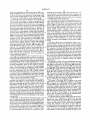
FIG. 3 is a timing diagram of the circuit embodiment
it may take place after the addressing process is com
of FIG. 2. Although outputs 252 and 253 of counter 250
pleted. At the end of the voice or data transmission,
are not utilized in the circuit of FIG. 2, they are in
switch 120 is deactuated at a time corresponding to T4
cluded in timing diagram FIG. 3 for the purpose of
of FIG. 3. The deactuation disables the transmitter and,
illustrating the operation of the particular type of John
if switch 280 is in position A, disables the encoder. The
son counter used in this embodiment. Commercially
available Johnson counters such as the MCl4022
counter produced by Motorola Inc. as well as other
low transition at the reset input 225 of timer 230 once
again causes the timer to begin its predetermined time
interval.
At time T5 the party being called responds with a
counters are entirely suitable for this application. Simi
larly, numerous timing circuits, such as analog one-shot 40 transmission of his own. This causes squelch input 65 of
type timers and clocked digital counter based circuits,
the formerly transmitting and now receiving unit to go
to be used for timer 230 will occur to those skilled in the
to a logic low causing audio enable output 75 to go low
turning on the receiver’s audio allowing the user to hear
The timing diagrams of FIG. 3 includes FIGS. 3A
the message being received. The received audio also
through 3M wherein FIG. 3A represents the signal at 45 turns on the reset input 225 of timer 230 thereby holding
switch input 135, FIG. 3B represents the signal present
the output at a logic high. At time T6 the received
at the reset input 225 of timer 230 and FIG. 3C repre
message ends causing the squelch input 65 to go back to
sents the signal present at the output 232 of timer 230.
a logic high which in turn causes the audio to be dis
art.
FIGS. 3D, 3E, 3F and 3G respectively represent the
abled by the high going transition at output 75. The
signals present at outputs 252, 253, 254, and 255 of 50 change at input 65 causes timer 230 which had been
counter 250, respectively. FIG. 3H represents the signal
reset by the logic high on input 65 to start its time inter
present at transmit enable output 105. FIG. 31 repre
sents the signal present at encode enable output 115 in
the case of switch 280 set in the A position. FIG. 3]
val once again.
At time T7, the user once again actuates switch 120 to
respond to the message received between T5 and T6
represents the signal present at squelch input 65. FIG. 55 causing input 135 to go high and reseting the timer. The
3K represents the signal present at audio enable output
counter is once again clocked to the next count causing
75. FIG. 3L represents the signal present at encoder
its output 255 to go to a logic high while outputs 252,
enable output 115 in the case of switch 280 set to the B
253 and 254 are at a logic low. The transmitter is en
position. FIG. 3M represents the signal present at de
coder input 25.
abled by output 105 and, if switch 280 is in" position 8.
At a time T1 OF FIG. 3 the user actuates switch 120
the encoder 100 of FIG. 1 is once again enabled. If
switch 280 is in position A an unencoded transmission
will occur. If the encoder 100 is enabled, voice or data
may be transmitted after the address is encoded and
transmitted. If the encoder is not enabled voice or data
for a ?rst time to initiate a call causing a logic high to
appear at input 135. This causes a logic high to appear
at the reset input 225 of timer 230 which in turn causes
the output 232 of timer 230 to become active and go to 65 information may be transmitted immediately.
a logic high. Counter 250 is clocked at this time causing
output 253 to go high, output 252 to go low and outputs
254 and 255 to remain at a logic low. Assuming the
At time T8 switch 120 is deactuated causing input 135
to once again return to a logic low. This causes a high
to low transition at the timer reset input 255 which
4,501,017
10
restarts the timing of the predetermined time interval.
and switch 120 and delivers appropriate signals to re
The signal at output 255 of counter 250 is fed back
ceiver audio 40 and transmitter 325. It will be appreci
through inverter 270 and AND gate 215 to prevent
ated that transmitter 325 may alternately include an
further actuations occurring while the output 232 of
encoder such as encoder 100 and receiver 10 may alter
timer 230 is active (logic high) from clocking counter 5 nately include a ‘decoder such as decoder 20. Preferra
250. Therefore, there is no change in counter outputs
bly, however, the micro-computer would handle these
252, 253, 254 or 255 on any subsequent transmission
functions. Micro-computers such as the widely avail
unless timer 230 times out to the end of its time interval.
able Motorola MCl46805G2 as well as others is suitable
This will cause the counter 250 to reset to its original
for performing these functions.
state prior to time T1.
The time interval from T9 to T10 represents a re
ceived message similar to that occuring between time
T5 and T6. Although counter 250 is at a different count,
the controller 30 responds to this incoming message in a
manner identical to its response between T5 and T6.
In this embodiment, ROM 320 serves as a “code
plug” which is used to program the transceiver with
various options and information necessary 'to the trans
ceivers standard operation. Information such as tone
duration, tone frequency, etc may be stored therein and
programmed to meet various user or system require
Similarly, the decoder responds to subsequent transmis
ments. The switch 280 of controller 30 is preferrably
sions such as that occuring between time T11 and T12
replaced by one bit of digital information in ROM 320
the same as transmissions occuring between time T7 and
for system 300.
T8 as long as the timer output 232 is at a logic high.
FIG. 5 shows a flow chart of one method of program
At time T13 the output 232 of timer 230 becomes 20 ming micro-‘computer 310 to perform the functions of
inactive and goes to a logic low indicating that the
the present invention. This flow chart is designed to
predetermined time interval of timer 230 has expired.
parallel the operation of hardware switch controller 30
This resets counter 250 to its initial state just prior to
and the reader should be aware that decision blocks do
not uniformly show the result of a “yes” answer at the
time T1. Actuations of switch 120 occuring subsequent
to time T13 will cause controller 30 to respond as it did 25 bottom of the diamond shaped blocks. It will occur to
at time T1 restarting the entire cycle.
At time T14, the response of controller 30 to cor
rectly encoded incoming messages is shown. That is,
the conversation is inititated by another transceiver
addressing the transceiver of the present user. At this
time input 25 makes a low to high transition as a result
of a correctly decoded address by decoder 20. This
causes a logic low to logic high transition at the timer
reset input 225 which in turn causes the timer output
232 to go high. The incoming signal at input 25 also
causes counter 250 to be clocked causing its output 253
to go high and its output 252 to go low. Outputs 254 and
255 remain at a logic low. Since a decoder output im
plies that a signal is being received, squelch input 65
makes a logic high to a logic low transition and audio
enable output 75 goes low turning on the receivers
audio circuits.
At time T15 the incoming message ends causing the
timer 230 to begin timing its predetermined interval and
those skilled in the art that many other flow charts will
result in ?rmware which will equally well perform the
desired functions, therefore, the flow chart of FIG. 5 is
not intended to be limiting as the only program se
quence which would perform the function of the pres
ent invention.
Program step 400 of the flow chart of FIG. 5 encom
passes the ?rst steps of the program wherein a timer,
counter and other circuitry will be initialized upon
powering up the system. The program looks for a
switch actuation at step 410 and if none is found pro
ceeds to step 420 where the receiver squelch circuit is
inspected to see if a radio frequency carrier is present. If
carrier is present the timer is reset and a brief delay
occurs at steps 430 and the program is returned to step
410. If the switch has been actuated step 440 checks to
see if the timer is running. If not, step 450 enables the
audio until step 460 detects a switch release. Until the
switch release occurs periodic delays are encountered
the audio to be disabled. It should be noted that after 45 through steps 470 until the switch is released.
time T15 controller 30 is in exactly the same set of logic
When the switch is released the timer is reset at step
states that it was in after time T2. Therefore it is evident
480 and the program returns to step 410. If at step 440 it
that a response by the user of actuating switch 120 will
is determined that the timer is running, step 490 clocks
cause the same response as that which occurred at time
the counter. If the counter’s ‘count equals 2 at step 500,
T3. That is, a transmission with an encoded address will 50 the encoder is activated along with the transmitter at
occur. It will be evident to those skilled in the art, that
step 510. The transmitter remains activated until steps
the minor modi?cation of causing no address encoding
520 and 530 determine that the switch has been released.
when communication is initiated by receipt of a cor
At that point. Step 540 stops transmission and step 550
rectly encoded incoming message may be readily imple
resets the timer. The program is then returned to step
mented by clocking counter 250 more than once as a 55 410.
result of a logic high at the output of AND gate 210.
If at step 500 the count is not equal to two, step 560
Turning now to FIG. 4, it will be evident to one
disables the clock to the counter. Step 570 determines
skilled in the art that a microprocessor or microcom
whether or not the user desires to encode upon each
puter is ideally suited to perform the functions of con
transmission or not. If so the program returns to step
troller 30 in an equivalent embodiment shown in FIG. 4
510 and if not the program simply turns on the transmit
as system 300. In this system a microcomputer 310
ter at step 580 without enabling the encoder. The pro
along with its associated “code plug” ROM 320 will
gram then proceeds to step 520.
preferrably perform the functions not only of controller
If at step 420 it is determined that carrier is not pres
circuit 30 but also of other radio functions such as that
ent, step 590 determines if a message has been is prop
of the address decoder 20 and address encoder 100 of 65 erly encoded and correctly decoded. If not step 600
the system of FIG. 1 but this is not intended to be limit
checks to see if the timer’s interval has expired. If not a
ing. In this system, micro-computer 310 accepts incom
ing information from receiver 10, squelch circuit 60,
delay is encountered at step 610 prior to returning the
program to step 410. If the timer’s interval has expired
4,501,017
11
at step 600, the audio is muted at step 620 and the timer
is reset at step 630. The program then returns to step
410.
If at step 590 the signal was appropriately decoded, 5
step 635 checks to see if the timer is running. If so, step
640 resets the timer and step 660 enables the receiver’s
audio. The program then returns to step 410. If at step
635 the timer is not running, step 665 clocks the counter,
step 670 resets the timer, step 675 enables the timer and 10
step 680 enables the audio. The program then returns to
step 410. If it is desirable not to transmit an address code
on the ?rst actuation of the switch 120 occuring after
12
Motorola MC146805G2P microcomputer in conjunc
tion with the MCM2802P programmable ROM. The
details of using this particular widely available micro
processor/microcomputer family are well known and
documented in the “M6805/Ml46805 Family Mi
crocomputer/microprocessor User’s Manual” pub
lished by Motorola, Inc., 3501 Ed Bluestein B1vd., Aus
tin, Tex. 78721. The contents of the above referenced
manual is hereby incorporated by reference. Details of
the microprocessor itself may be found in the com
monly published “Motorola Microprocessor Data Man
ual” in the section entitled “MCl46805G2”, the con
tents of which is also hereby incorporated by reference.
receipt of a correctly encoded message, step 665 should
In FIG. 6, the actual transceiver functions are repre
clock the counter twice, otherwise an address will be 15 sented in block diagram form and one skilled in the art
encoded on the ?rst transmit.
will readily know how to accomplish the appropriate
interfacing to those functions. Also, pin numbers for the
Turning now to FIG. 6 a diagram of the actual hook
plastic dual in-line package versions of the microcom
up for the preferred ?rmware embodiment of the pres
puter and ROM are circled and shown adjacent the
ent invention is shown. This embodiment utilizes the 20 appropriate I.C. terminals.
0000
00:10
0020
00:30
0040
0050
0060
0070
0080
0090
0000
000:0
000:0
0000
001530
001-‘0
0100
0110
0120
01:30
01110
01:50
0160
0.1.70
0180
0190
0100
011:0
010:0
0100'
011:0
011-"0
0200
0210
02220
02:30
02-10
02:50
02:50
0270
D0
00
00
ll 0
00
00
00
00
‘2.4
09
0 0 ED
3E:
:30 EEiEI
‘1F 0 55
U ‘:‘3
80 0 E16
80
0 0 7‘?
3E:
I36, 21)
AE
1-NEI 55E:
153:7
13A
0 55 E17
CC
75
(34‘:
A6
23F‘
72 1. 2
137
E16 38
03
FE
137 Ci:
~70
13
91) 26
[1 0
0U
(1 ll
00
[J [l
00
l] 0
00
1.6
21
3A
“'1 I51
(36*:
U 1.
6:1‘:
01
33H
26
00
00
00
00
00
00
00
00
02
at:
1"?
2:0
:30:
01-"
68
12:1)
1313
0::
0-?
TABLE
l] l] l] 0
U U [l 0
l] l) l] U
U l] 0 O
l] U U l]
U0 00
0 0 0 l]
00 00
17 U 1
ll. 0 Q6
E56 1. 0
0 4!’) E57
Elli; 3 5:
0 1’. 0 0
3|:- :23‘?
l3 8 E'- D
3'1’: 3 El
I
U0
l] 0
00
l] 0
00
00
U0
00
18
1 ‘1
27.6
13E:
F7
4‘?
13F
88
[1 U
0U
[l l]
U l]
[l 0
U0
UU
00
[1 1
15:7
[1 ‘I’
QC’:
131:
81.
(‘3191
E16
13C .20
'
{-5161 If U Il. I35: 0.1.
9 U 3 40 22 :5
‘if 0
1M:
0
J):
11. 1:1 00 20
12:7
0:11‘
F, -.
00 00 00 ()0
(10 00 00 (10
00 00 00 00
(10 00 00 00
00 00 00 0O
00 00 00
0O 00 00 0 0
00 00 00 0 0
81 ms :50 E17
0A 15:7 :31) 1312)
(20 04: #12 01 15:7
5:7 ‘3A ms 021 0:7
3A 3C 226 1-12 E11
113 :72: 01:‘; 12:1?
81 1F 0:2 15:
15:13) 80 ~16: 0:0
3C
7’
02; (3:3 31: 15:1)
12:1) 88 0e: 01
0
1:11.: 04 97 31::
F1
'01; :30 12 72
E=D ‘
12:4. 12:7 122:7 :31:
Ell‘)
136 2.1:: 15:7 31::
E11)
12:7 131:) ms at:
A6
an. 31') 20 1:12:
6
FF‘ 12:7 75 M:
12 (>1
A1 0P 2:, 0:3
(#4
"211 :20 0:5 12:7
7'5
E16
15:7
0a :31:
38 09
0E 231-‘
138
15:7 0a 1221* 09
E16
‘m :24, F1) 01
90
0 ll
00
00
00
00
00
(l 0
00
19
3E:
‘90
46
13 E1
l. ‘1
BF
0 t]
00
00
00
00
(l 0
00
l) 0
01
A6
1:1: :20 13:1 115:
:31?
12:3
171)
1:7
23::
(30
‘.2 It
(‘H->1
E17
12:4.
130
01;:
<71) ‘9D ‘9D
0:3 ms 0 II.
~41: 227 F7
12:7 0 ‘9 8 0
[I 8
127
9D
12:7
22c
0-1
m:
01)
31-1‘
12
ct:
31:
:39
013
11::
ms
00>
12:4:
01
0:2:
ms
7E1
1:7 0:21
00 12:7
0111‘ ;'-"~;;.
12;:7
0:5 :71)
77 07
07 :10:
U 6)
4,501,017
13
TABLE I (cont ' d)
02.80
0290
0200
025:0
0200
0200
0212230
020140
0300
0310
0:320
03:30
03-40
00:00
0:300
0:370
0:300
0:090
0300
030:0
05030
0300
0350
(ISFU
0400
0410
0420
0430
0440
0450
0400
0470
0480
04-00
0400
040:0
0400
0400
0450
(MP0
0500
0510
0520
0530
0540
0550
[1560
0570
0580
0590
0500
051310
0500
0500
050:0
USF'O
U 3 CC 0 3
I31) D U 538 77 27
1C
(58 (18
I1 '5 I) 7 U I] (I 2 E10 [1DIE: 1 7
I37 13!)
02 U 9 U l’. 38 ‘5C 0 E: U 2 3 ‘I
:39 3D
E17 I] 2 0 8 (3D PIE: I] 3 (68
1 II. 68 '1
(-1 6 22 1 E17 I] "I 1 0 U 0 I] E
7 [1
1 2 <58 96 0 II. E517 <5 6 8 LI.
‘,7 3
E: D IE: 1 6 7 2:’. 5 D3 I] 0 038
E: 1
638 1 ‘I 6 8 8 IL 1 5.] 038
UA
0 CI '7
1 D A C’) IEI 0 E17
C’) 8
A3 6 0
‘I "ID F6 Ii A
7 1.
.
r11].
I 26 I] 2 3F‘ 713
I) I:
7 "I
FIE:
El 1
I351?’
[1
I36
27
III: I]
I) "I
I) 9
7 (3
f
[3A 553 U
2:51
E3 1
l: I] I25: 7'
II.
IIIU D .2’ 1 0 8
If} 1
U I3
5
I51?’
It’) E17 II] 0 I. I.)
(SA
0 ‘I
U 7 If 0 (1 21 I. (11 O 7
01
I] 8
1'17 I. 3 L U ":3 [I
0 E:
I3 [I
0 3 E: 1 (SE 27
I] F
39
1 3 1 2 6C 20
0 Ii’
6) I:
E: 1 (SF 227 ED
08
630
7 0 2 7 1. 6 1 ‘I
2U
EIEI
F2 3C 7 0 A6
15
E38
62
72 1 0
2D
1E
DE 0.1. 5 6C 1 "I
II. I?
I) 8 Y2
II. 8 7 2 1. 6 72
72
IE: 6 16
9C 2 0 76 1 4
"I 03
6C 0 6
0 ‘I E6 ‘If! Z 0
:38
1 ‘I 7 2’.
7 2 1 D 0 ‘I 81
I] ‘I
1D 0 0
1C 0 0
69
E17 60¢!
E19 6E:
6E:
26
E '"I 1F
AD [)22
68
E17
2 1 B7
E56 3A
00
7 2. I] 3
39 0 3
08 0 0
0E:
{-06 (S U
2?. 0 0 <5
U 1 F2
01
Q6 FF I37
Q 6 0 55
U 9 8F
01.
II. 7 72
Z’. 0 3F
U 3 I37’
3 Q 0 55 CD
34 2 0
0 IL
CD
0[I 1 40.
U 3 351 I] F
7 1 (32
I] II.
2 0 II. 3
2E: CD
5A (1D .
I] 3
ED
42
7' 1
E17 0 1’
I3 ‘I
1 E3 U I] cc:
6A
0 5 I] I?
I] 55
U 6 72 0E;
"I 2
I] (‘5 II) E}
313i
I] 1 B‘I 20
CD I) 1
if: I]
U 8 I] 3 01
2’. [1 U 3
I] II.
2 I) E13
‘9C E: I.)
P: (I)
I3? {5
E54 :5
312 CD
('1') 8
A e3
I37
68 I] C
1 I)
5071
CI
E17 U 3
I] 0
II. I:
0D
E17 3C
E12
UU
55 D
I537 0 9
I] 22
7 If
UD
22 7 0 55
72
1D
A6
I] I] 0 II)
UC
1 I:
E03
I] I: 13F
if [1
I916 I
E37
I] “I E16:
E17
(1 9
(S8
" "I I
I]
1.) .Q
(113
.'
70')
m.
My ,
"I IEEZII)
,...
:58
‘I I.
11
3F"
2. 0
(5C
‘I13
20
0:1
10
3F
4:3
‘.20
‘I6
72
‘I8
‘I53
EH5
08
[:0 I] 1
3A 1A
0A 3A
E4
01 03 A
5A $3. 0
(:0 I] II
3F
27
46
05
6 1.
1 I51
II. lal
72
(39
0:7
:20
1.0
(:9
12:4
01
1E:
01
0:3
0:7
IE5
0D
F2
0 (1
20
Z‘I
19
BE:
0E
6A
26
34
I] 0
6E
(31*!
U1
10
‘IA
0 3 0 <5
(III: I] C
[1 U 3A
1 I)
CC
0D
30
I516
23 1
38
l‘) 4
7[)
90
E: 1
'2 0
3D
20
1D
Z 6')
[1E
3A
‘7 II)
I] A
72
71
I) '55
I] 1
1 13
A6»
I] <5
[ID
1 P1
76>
F7 E
II. IE!
1 I:
I5: 7
E17
70
EA
224
72
1 "'I
68
ll?
1C
DIE:
CD
39%
(S C
0 13:.
17
01
72
E17’
0 E5:
712’.
07
00
4,501,017
15
0600
0610
0620
0630
0640
0650
0:500
0670
0680
0690
06m]
06030
06130
0600
06,50
l'léF'll
0700
0710
07220
0730
0740
07:50
0760
02'?!)
0780
02190
0760
07130
03-’(30
A6 [16
(3E1 10
A6 3 U
2' E37
62 8
E")
El?
(3E
3F
E16
44
12.’.
27
0?
C8
‘all
E39
13E:
012;:
2C)
E17
9? A
ED
7”].
E37
'30
20
El?
1 [:1
130
30
120
E11
28
22E:
at:
20
16
13C
' 7
1A
UK:
08
15
GE
20
15
I906
E56
10
E7 2'5
00 25
07D!) EB
07E0
07l'-"0
0800
0810
0320
0830
0840
0850
0860
0870
0880
00
36
36
26
U7
7?
[37
3E:
[37
13
AF
lFFO 00
/_
In]
E17
27
136
DE:
U“?
87
0‘?
1.0
[115
E17
[)0
230
OF’
3F
10
12
A6
26
40
:3 (S
[17
2'30
00
A6
02
E37
:2 5)
‘l3
I37
CID
E16
70
04
H7
013
13$
I37
I37
Oil)
RU I23 0C
213 0-“: 7230'
0“? 3A 2D
E16 15: {5:9
20 (-1‘? 3C
9'5 2E: (IE;
U‘i 3A 19
02 E51)’ 0‘?
2F BE: 29
CD 07 Ali:
Eu’: 08 E0
0]. q ‘,7 E5’
2A 01 40
10 (5A O3
(‘)8 E16 03
3:9! 12
1:
00
053 E7 0‘?
(11 39 02
E15» I37 48
ED B6 37
2E E31 30
E37 A6 21E
00 00 00
U0
0U
I313
20
0F
F2 00
:21 E17
E57
52:? 6 l:
IQIE
All.
‘9C
22:7 09
CD 08
(34 E37
:36
E37 1-‘?
:52 E17
(36 A4
ILl'Ii 72
(32 E313
[1C 128
‘£0 1C
l§§l7_
F117]
[12
1D
08
121
E17
E16)
137
CD
U '5
C (I:
72
17
E17
08
I35
Elli:
{12
U1
01‘5
0 ll. 1.8
LEE? M
:5‘. If)! 130
20 00
15
18
0C
20
E16}
E37
UH
0.1‘.
3D
5:?
2c’)
E1
DE
2'5
E?’
A6
B7
27
26
BD
00
tzlfl
13E}:
1*:
11
i3‘: 1.
07
0%
4E
1311-:
2A
1 091
E37
00
BE 27 1531c’) 1313 I37
il-"i 1 fl 36> 53F CD
0:3
.zilf) 1
m
Mr
El;
EH5 3‘.
[Wt 13!: 13A 2.0 2'17
BC LED 17:0 1.253 J1EE:
‘.50 0E:
0-4 73A,
3H
I37
20
1'53
81
1C
2'?
13¢‘.
E37
01
E16
81
{5:7
AF.‘
E16
20
20
00
00 U0 ()1 76
ABLE II
00
2E:
30
86
F8
E16
B?
07
313
0D
U0
UP:
00
pl (3.
7
a.
aL-LI
n5
42
01
15
17
CC
4..
21
18
04
20
06
16
5:9 28
Ali: 23 CD
E6 07 E0
E0 3:: 0-0
3D FE‘ QIF-i
10
02
26
3D
A6 IE5: 5:7
3A E6 1E:
1E: E10 EID
1E: E11 3D
0A E3 6 RE
08 F216 113:
00 00 00
74 20 31
20 ‘i9 élI-II
06 17 05
00
0C
3A
1A
16
E56
as
E13 A6
[316 (11
EM
I337
0A
E4
E17
23
$222
1335
09.
E16
0B
1''?
3A
A6
1E5
28
AH
E37
1F '
0C
20
18
AD
B9
05
81
3E!
BE:
16
1'5
99
20
C7
15
36
-£-,
HE!
04
3C
88
00
E5"
05
06
313
25 01 ‘i7
"
E7
E11
01 ‘i0 BE:
20
Elf-‘l
00
E10
26
E11
E10
00
'3 "P
63
0E
3:3
ED
04
4E
AF
00
38
41 1;
03 0C
E316 2E
E17
1E: E31)
0A $1 (‘Q
2E E10
00 00
I50 20
ED
01
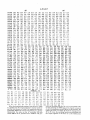
When the hexadecimal program code shown in Table
I is loaded into the microcomputer’s internal memory
and the code shown in Table II is loaded into the pro
grammable ROM, the circuit will perform in a manner
substantially the same as that of controller 30 with
switch 280 in the A position and in addition will per
no
form the decoding function for a 9-9-9-9-9 ZVEI code
on data entering the PB6 input. If an encode is desired
on each transmission (switch 280 in the B position), the
tenth byte in line 3 of Table II should be changed from
2E to 3E. Also, theencoding function isperformed and
the output appears in the form of a 350 millisecond,
17
4,501,017
18
1200 Hz tone in digital form at outputs PDZ and PD3
transmitted by said transmitter; and wherein said third
when the microcomputer is clocked at a bus speed of 1
control signal allows said encoder to be enabled ony
MHz. This output is processed by a two bit D/A con
when said counter indicates that switch is being actu
verter 690 and a low pass ?lter 695 prior to being trans
ated for a ?rst time within said time interval.
mitted by transmitter 325. The output of receiver 10 is 5
8. A multiple function switch controller in accor
processed by a low pass ?lter 700 and then limited by a
dance with claim 7, wherein said encoder includes a ?ve
limiter 710 prior to input into the PB6 terminal of the
microcomputer.
tone sequential selective calling encoder.
9. A method of controlling the operation of a switch
Thus, it is apparent that in accordance with the pres
in a transmitter, comprising the steps of:
ent invention a method and apparatus that fully satis?es 10
timing an interval following operation of said switch,
the objects, aims, and advantages is set forth above.
the duration of said time interval being indepen
While the invention has been described in conjucntion
dent of the operation of said switch;
with specific embodiments, it is evident that many alter
actuating said switch outside said time interval;
natives, modi?cations and variations will be apparent to
those skilled in the art in light of the foregoing descrip- 15
tion. Accordingly, it is intended that the present inven
tion embrace all such alternatives, modi?cations and
variations as fall within the spirit and broad scope of the
alerting the user of the status of a communication
appended claims.
What is claimed is:
1. In a transceiver including a transmitter and a re
ceiver, a multiple function switch controller for con
comprising:
trolling the transceiver by the operation of a switch,\‘
a timer responsive to said switch for establishing a 25
time interval, the duration of said time interval
being independent of the operation of said switch;
?rst means, coupled to said timer and responsive to
actuation of said switch occuring during said time
interval, for producing a ?rst transceiver control 30
signal wherein said ?rst control signal establishes a
?rst operational mode for said transceiver; and
second means, coupled to said timer and responsive
to actuation of said switch occuring outside of said
time interval, for producing a second transceiver 35
control signal wherein said second control signal
establishes a second operational mode for said
transceiver;
whereby, said switch controller allows said switch to
control a plurality of transceiver functions.
40
2. A multiple function switch controller in accor
dance with claim 1, further including:
means, responsive to said ?rst control signal, for se
channel upon actuation of asid switch outside of
said time interval; actuating said switch during said
time interval; and
enabling said transmitter upon actuation of said
switch occuring during said time interval.
10. A method in accordance with claim 9, further
including the steps of:
enabling an encoder upon a ?rst of said actuations of
‘ said switch occuring during said time interval; and
inhibiting said encoder upon subsequent actuations of
said switch occuring during said time interval.
11. In a transceiver including a transmitter and a
receiver, a multiple function switch controller, compris
ing:
means for detecting operation of a switch;
means coupled to said receiver for monitoring the
activity of a selected communication channel;
a timer, responsive to either said monitoring means or
said detecting means, for establishing a time inter
val, the duration of said time interval being inde
pendent of the operation of said switch;
means, responsive to actuation of said switch during
said time interval, for enabling said transmitter; and
means, responsive to actuation of said switch outside
of said time interval, for annunciating the status of
said communication channel.
12. A multiple function switch controller in accor
dance with claim 11, further including:
means for detecting a ?rst actuation of said switch
lectively enabling said transmitter; and
annunciating means, responsive to said second con 45
trol side, for annunciating the presence of activity
on a selected communication channel.
occuring during said time interval; and
means for enabling an encoder during said ?rst actua
tion.
13. A multiple function switch controller in accor
dance with claim 12, further including means for inhib
3. A multiple function switch controller in accor
dance with claim 2, wherein said annunciating means in
iting said encoder during second and subsequent actua
includes means for selectively directing audio fre 50 tions of said switch occuring during said time interval.
quency signals to a loudspeaker.
14. In a transceiver ncluding a transmitter and a re
4. A multiple function switch controller in accor
ceiver, a multiple function switch controller, compris
dance with claim 2, further including an encoder cou
ing:
pled to said controller and said transmitter for encoding
an address to be transmited by said transmitter;
55
said encoder being enabled whenever said transmitter
means for detecting actuation of a switch;
a decoder coupled to said receiver, for decoding
received signals of a predetermined type;
is enabled.
5. A multiple function switch controller in accor
dance with claim 1, further including a counter for
counting the number of actuations of said switch occur
a timer, responsive to either said detecting means or
said decoder, for establishing a time interval fol
ing during said time interval.
6. A multiple function witch controller in accordance
with claim 5, further including gating means, responsive
to said counter, for providing a third control signal only
on predetermined counts of said counter.
7. A multiple function switch controller in accor
dance with claim 6, further including an encoder cou
pled to said transmitter for encoding an address to be
lowing each switch actuation or each decoding of
a received signal of a predetermined type; and
controller means, responsive to said timer and said
switch, for placing said transceiver in a ?rst mode
of operation if said switch is actuated during said
time interval and placing said transceiver in a sec
ond mode of operation if said switch is actuated
outside of said time interval
15'. A multiple function switch controller in accor
dance with claim 14, wherein:
19
4,501,017
20
enabling said transmitter upon actuation of said
switch occuring while said output is said predeter
said ?rst mode of operation is associated with said
transmitter; and
said second mode of operation is associated with said
receiver.
mined signal;
.
enabling an encoder to encode said transmitter’s
transmitted signal when said count equals a ?rst
16. In a selective calling transceiver including a trans
mitter and a receiver, a multiple function switch con
predetermined count; and
inhibiting said encoder when said count is equal to a
second predetermined count.
troller for controlling the transceiver by the operation
of a switch, comprising:
a decoder for decoding a received signal including a
26. In a transceiver including a tramsitter and a re
ceiver, a switch controller for controlling the trans
predetermined address;
ceiver by the operation of a switch, comprising:
a timer, responsive to said decoder, for establishing a
time interval following each decoding of a re
a timer for establishing a time interval in response to
ceived signal including a predetermined address;
?rst means, coupled to said timer and responsive to
?rst means, responsive to actuation of said switch
during said time interval for producing a ?rst trans‘
actuation of said switch during said time interval,
for producing a first control signal to selectively
enable said transmitter;
second means, coupled to said timer and responsive
said switch,
ceiver control signal; and
second means responsive to actuation of said switch
outside of said time interval for producing a second
transceiver control signal.
17. A multiple function switch controller in accor
to actuation of said switch outside of said time
interval, for producing a second control signal;
20
annunciating means, responsive to said second con
trol signal, for annunciating the presence of activ
dance with claim 16, wherein said ?rst control signal
ity on a selected communication channel; and
establishes a ?rst operational mode for said transceiver
a counter for counting actuations of said switch oc
and said second control signal establishes a second oper
curing during said time interval.
ational mode for said transceiver.
27. A switch controller in accordance with claim 26,
25
18. A multiple function switch controller in accor
further including gating means, responsive to said
dance with claim 17, further including:
counter, for providing a third control signal only on
predetermined counts of said counter.
means, responsive to said ?rst control signal, for se
28. A switch controller in accordance with claim 27,
lectively enabling said transmitter; and
annunciating means, responsive to said second con 30 further including an encoder coupled to said transmitter
for encoding an address to be transmitter by said trans
trol signal, for annunciating the presence of activ
mitter; and wherein said third control signal allows said
ity on a selected-communication channel.
encoder to be enabled only when said counter indicates
19. A multiple function switch controller in accor
that said switch is being actuated for a ?rst‘ time within
dance with claim 18, wherein said timer is also activated
said time interval.
in response to said switch.
35
29. A switch controller in accordance with claim 28,
20. A multiple function switch controller in accor
wherein said encoder includes a ?ve tone sequential
dance with claim 19, further including means, respon
selective calling encoder.
sive to actuation of said switch during said time interval,
30. A switch controller in accordance with claim 29,
for enabling an encoder.
wherein said annunciating means includes means for
21. A multiple function switch controller in accor
selectively directing audio frequency signals to a loud
speaker.
dance with claim 20, further including a counter means
31. In a selective calling transceiver including a trans
for counting the number of actuations of said switch
mitter and a receiver, a switch controller for controlling
during said time interval.
the transceiver by the operation of a switch, compris
22. A multiple function switch controller in accor
dance with claim 21, further including gating means, 45 mg:
a decoder for decoding a received signal including a
responsive to said counter for allowing said encoder to
predetermined address;
be enabled only on predetermined counts of said
a
timer,
responsive to said decoder and said switch,
counter.
for establishing a time interval folllowing each
23. Av multiple function switch controller in accor
decoding of a received signal including a predeter
dance with claim 22, wherein said gating means allows
mined address and following predetermined opera
said encoder to be enabled only when said counter
tions of said switch;
indicates that said switch is being actuated for a ?rst
?rst means, responsive to actuation of said switch
time within said time interval.
during said time interval for producing a ?rst con
24. A multiple function switch controller in accor 55
trol signal;
dance with claim 21, wherein said annunciating means
means responsive to said ?rst control signal for selec
tively enabling said transmitter;
includes means for selectively directing audio fre
second means, responsive to actuation of said switch
quency signals to a loudspeaker.
outside said time interval for producing a second
25. In a transmitter, a method of controlling a switch,
control signal,
comprising the steps of:
annunciating means responsive to said second control
providing a timer responsive to said switch for estab
signal for annunciating the presence of activity on
lishing timing intervals in response to operation of
said switch;
a selected communication channel;
means responsive to predetermined actuations of said
switch during said time interval for enabling an
detecting whether or not an output of said timer is a
predetermined signal;
counting actuations of said switch occuring while
said timer output is said predetermined signal to
establish a count;
65
encoder; and
counter means for counting actuations of said switch
during said time interval.
*
*
1F
*
*